Guangzhou JiTian Lighting Company Limited
www.stagelightingzone.com
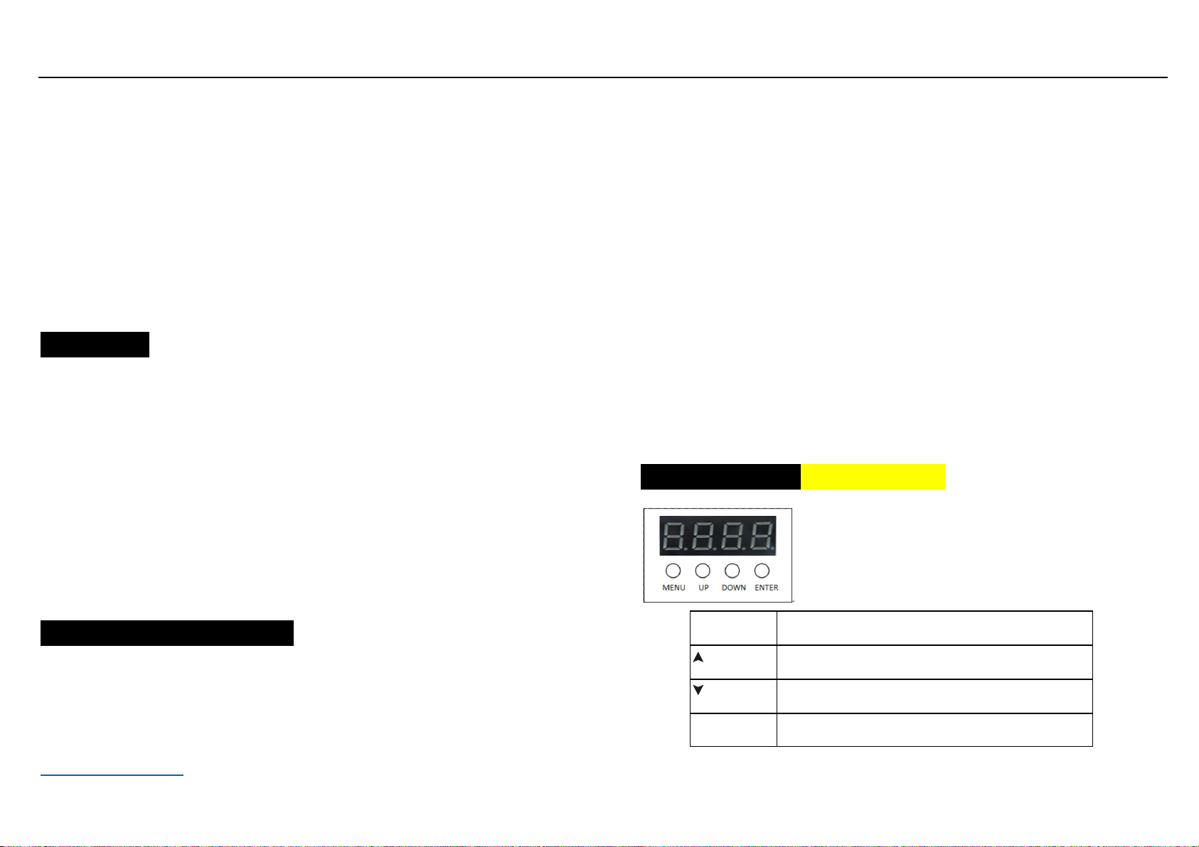
according to different requirements. Press the ENTER button again to exit to
the previous menu mode. If you press the MENU button, the display will
advance to the next main menu mode.
"SySt" system setting mode
Select “SySt” (system setting mode), press ENTER button to enter the next
level menu, display “teSt”, use UP/DOWN button to select different settings
between “rF24”, “UIFI” and “Led”. When the “teSt” display is selected,
press the ENTER button to confirm, the system will enter the self-test mode,
the display will be in “red”, “Gree”, “blue”, “UhIt”, “yeLL”, “PurP”,
“FuLL” Automatically switch between, display the menu at the same time
the corresponding color of the light will also light, if you press the MENU,
ENTER button to exit to the previous menu mode. At this point, the self-test
mode stops.
When the “rF24” display is selected, press the ENTER button, the system
will control the power of the 2.4G wireless module, turn on the power when
“on” is displayed, and turn off the power when “oFF” is displayed. Press the
MENU, ENTER button to exit to the previous menu mode. The parameters
will be automatically saved after exiting. If you use the 2.4G wireless
module to receive signals, you must select "rF24" in the "on" state.
When the "UIFI" display is selected, the system turns on the power of the
WiFi module and enters the handset dimming control mode. The parameters
will be automatically saved after exiting.
When exiting to the “SySt” display, the system will automatically turn off
the WiFi module. At this time, the Wifi module device cannot be searched.
When the menu is selected to “WIFI” display, WiFi module can be used to
receive signal control. Open the WIFI setting page of the mobile phone and
click on the link with the WLAN name “LEDxxx”. After the link is
successful, open the Led Wifi software to scan and select the single point
control. Can carry out the corresponding operation interface. When the WiFi
signal reception is interrupted unexpectedly and cannot be controlled
normally, the APP control interface can be opened again to operate again.
When the “Led” display is selected, press the ENTER button and use the
UP/DOWN button to select “on” or “oFF”. When “on” is selected, the
display is always on, if “oFF” is selected, when there is no button The
display will automatically turn off approximately 5 seconds when pressed,
and the display will not turn on until a key is pressed again.
C: DMX512 Controller Mode
Press the MENU button until “Chnd” (channel mode) is displayed on the
screen, press the ENTER button to confirm. Use the UP/DOWN button to
select “6Ch” (6 channels mode) or “10Ch” (10CH channel mode) as
required, press the ENTER button to exit to the previous menu “Chnd”,
then use the DOWN/UP button to select “Addr” "(DMX512 address code
setting), press ENTER button to confirm, the display will show the
corresponding address code value. Use the UP/DOWN button to adjust the
desired setting of the address code from 1 to 512. In this case, you can
receive the DMX512 console control signal.
If you want to use this feature, please refer to the following diagram to set
the DMX512 address of the first 4 fixtures:
6CH mode: 1: A001, 2: A007, 3:A013, 4:A019
10CH mode: 1: A001, 2: A011, 3: A021, 4: A031
D: Master and slave built-in program control
When connecting multiple fixtures in the master/slave mode, except for the