GVD M1142 User manual

GVD
Mobile NVR M1142
Quick Start Guide


Mobile NVR M1142 Quick Start Guide i
Contents
Contents ....................................................................... i
Preface .........................................................................ii
About this Document ......................................................... ii
Declaration of Conformity.................................................. ii
Copyright and Trademarks ................................................ ii
Hardware Requirements..............................................iii
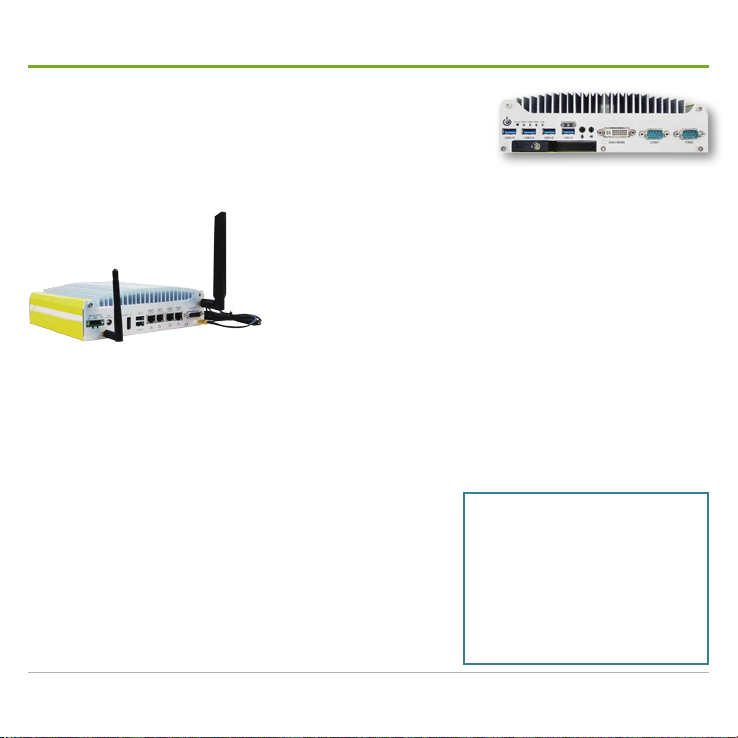
Introduction.................................................................. 1
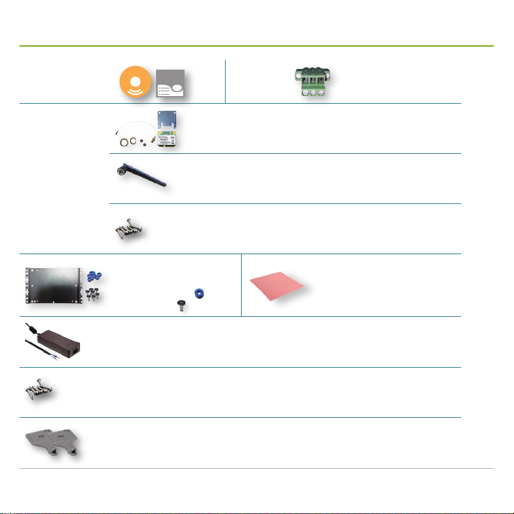
Accessories ................................................................. 2
Take a Tour .................................................................. 4
Front I/O Ports...................................................................4
Rear I/O Ports ...................................................................7
Onboard I/O Ports ...........................................................10
Install Hardware......................................................... 13
Open Pet Door ................................................................13
Install Internal SATA HDD/SSD .......................................14
Hot-swap a SATA HDD/SSD ...........................................16
Remove Bottom Cover ....................................................17
Install a WiFi Module .......................................................19
Install a SIM Card............................................................23
Install a 3G or 4G plus GPS Module (Optional) ..............24
Mount the Mobile NVR .............................................. 28
Wire DC-in Power Source ......................................... 30
Manage Ignition Power.............................................. 32
Wire Ignition Signal .........................................................32
Select Ignition Power Mode.............................................33
Set up Windows®...................................................... 34
Initialize HDDs........................................................... 35
Launch & Log in......................................................... 36
Use Installation Wizard.............................................. 37
Congure Network Parameters ................................. 44
Create Storage Volumes ........................................... 45
Auto-add a Camera ................................................... 46
Appendix. Install WiFi Device Driver & Connect WiFi
Network for the 1st Time............................................ 48
Appendix. Install 3G/4G Device Driver & Connect Mobile
Network for the 1st Time............................................ 51

Mobile NVR M1142 Quick Start Guide
ii
Preface
About this Document
This document is meant for the experienced users and integrators with hardware knowledge of personal
computers. If you are not sure about the description herein, consult your vendor before further handling.
We recommend that you keep one copy of this document for the quick reference for any necessary
maintenance in the future. Thank you for choosing GVD products.
Declaration of Conformity
FCC
This equipment has been tested and found to comply with the limits for a Class A digital device, pursuant
to part 15 of the FCC Rules. These limits are designed to provide reasonable protection against harmful
interference when the equipment is operated in a commercial environment. This equipment generates,
uses, and can radiate radio frequency energy and, if not installed and used in accordance with the
instruction manual, may cause harmful interference to radio communications. Operation of this equipment
in a residential area is likely to cause harmful interference in which case the user will be required to correct
the interference at his own expense.
CE
The product(s) described in this manual complies with all applicable European Union (CE) directives.
For computers systems to remain CE compliant, only CE-compliant parts may be used. Maintaining CE
compliance also requires proper cable and cabling techniques.
Copyright and Trademarks
This document contains proprietary information protected by copyright. All rights are reserved. No part
of this document may be reproduced by any mechanical, electronic, or other means in any form without
prior written permission of the manufacturer. Company/product names mentioned herein are used
for identification purposes only and are trademarks and/or registered trademarks of their respective
companies.

Mobile NVR M1142 Quick Start Guide iii
Hardware Requirements
Recording data is one of the most important parts for video surveillance, and hard disk drives are one of
the most important components to safely store the recording data.
It is always recommended that you use the hard disk drives certified by GVD. Find the list of the GVD-
certified hard disk drives at the link below:
http://www.gvdigital.com/gvdweb/html/document/Support_Lists/Certified%20HDD%20List.pdf
NOTE:
* GVD does not guarantee the system performance if a HDD model that is not certified by GVD is used.
* GVD recommends that you always use enterprise-level SATA hard drives for GVD enterprise NVR, Failover Server, Backup Server,
Extended Storage because it supports TLER (Time Limited Error Recovery), higher MTBF, higher Duty Cycles and typically include a
sensor for rotation and vibration.

Mobile NVR M1142 Quick Start Guide
iv

Mobile NVR M1142 Quick Start Guide 1
Introduction
Thank you for choosing GVD products. The M1142 is the mobile NVR
that comes in the rightful size among M1 Series, GVD's brand new line
of mobile NVRs. Powered by Intel®Celeron™ 1020E, the M1142 is a
fanless NVR to deliver fair CPU calculation with low power consumption.
The integrated Intel®HD Graphics 4000 Controller that brings DirectX11 also allows the NVRs to deliver
superb video and audio.
The M1142 comes with rich data connection including 3G/4G
and WiFi to stay tethered with the control center all the time. The
intelligent power management prevents startup failure and allows
the control center to watch over the car battery usage through 3G,
4G or WiFi. Isolated DIO on the other hand keeps the mobile NVR
connected with other in-vehicle devices such as a car door sensor,
and the change of DIO states can be sent to the control center.
If you opt for a GPS (plus 3G or 4G) module to go inside the mobile NVR, the control center can instantly
locate the vehicle that carries the mobile NVR on the map. Also on option is a G-sensor to measure the
vibration every couple of minutes and feed the data back to the control center. On the other hand the
mobile NVR is verified to be anti-shock and anti-vibration to guarantee more protection to the hard disk
drives onboard and ensures reliable video recording.
Four PoE LAN ports are featured on the M1142. Each port delivers power up to 25.5W and simultaneously
transfers data up to 1000 Mbps over a single CAT-6 cable. The
highly integrated mechanical design on the other hand allows
the M1142 to efficiently distribute the heat generated by the PoE
circuit and therefore makes the M1142 a very stable fanless NVR
with PoEs. The mechanical design is also modular to make the
NVR easy-to-install and maintain.
The simple and sturdy design makes the M1142 ideal for all kinds
of vehicles. It is your best choice for IP video surveillance on the
go.
Product Highlights
■Power over Ethernet
■Anti-shock / anti-vibration
■Rich data connections
■Intelligent power management
■Isolated DIO

Mobile NVR M1142 Quick Start Guide
2
Accessories
Driver CD &
User's Manual
DRIVERS
User’s
Manual
Terminal
Block
1 x 3-pin male terminal block
for 8~35VDC output
WiFi Module Kit
SparkLAN WPER-172GN 802.11b/g/n USB Half Mini Card
■802.11b/g/n ISM Band: 2.400 ~ 2.4835GHz
■Antenna: 2 x U.FL connectors (diversity antenna), 1T1R
1 x External Antenna
■RP-SMA male body & female inner contact
A few screws to x the module
■Stainless-steel round philips screws
Wall-mount Kit
■1 wall-mount bracket
■8 x rubber bumpers
■8 x M4 screws
Thermal Pad
One piece of thermal pad for internal SATA
HDD/SSD
Power Adapter (Optional)
24V/6.67A 160W AC/DC adapter
(for +8~35VDC output)
Internal HDD/SSD Screws
A number of screws to x the internal HDD/SSD
■Stainless-steel round philips screws
Outside-accessible HDD/SSD Keys
Two keys to the door to the outside-accessible and hot-swappable HDD/SSD SATA port

Mobile NVR M1142 Quick Start Guide 3
Accessories
Region Module (w/ GPS capability) & Wire External Antenna
4G+GPS
Module Kit
(Optional)
Southeast
Asia, Middle
East & partly
India (1800
MHz only)
Sierra Wireless® AirPrime™ MC7304
w/ 15cm internal wire
■LTE-FDD / HSPA+ (B1, B2, B3, B5,
B7, B8, B20)
1 x 3G or 4G External
Antenna
■RP-SMA male body & male
inner contact
1 x GPS External Antenna
■Length: 300cm
■RP-SMA male body & male
inner contact
A few screws to x the
module
■Stainless-steel round philips
screws
North America
& Latin
America
Sierra Wireless® AirPrime™ MC7354
w/ 15cm internal wire
■LTE-FDD, HSPA+, GSM/GPRS/EDGE,
GSM/GPRS/EDGE, CDMA (B1, B2,
B4, B5, B8, B13, B17, B25, BC0, BC1,
BC10)
3G+GPS
Module Kit
(Optional) All regions
HUAWEI MU609 Mini-PCIe
■HSPA+/UMTS quad-band
850/900/1900/2100 MHz
■GSM/GPRS quad-band
850/900/1800/1900 MHz
Sierra Wireless® AirPrime™ MC8705
w/ 15cm internal wire
■Operational bands: WCDMA 850,
WCDMA 900, WCDMA 1900, WCDMA
2100

Mobile NVR M1142 Quick Start Guide
4
Take a Tour
Front I/O Ports
Power
button DVI-I
connector
Hot-
swappable
HDD slot
Line-out
Reset
button
Status
LEDs COM2
Wireless
Status LEDs
USB 3.0
ports
COM1
Mic-in
Title Description
Power button
Turns on/off the system. Hit this button to turn on the system. Hit this button again to power off the system. Press-
and-hold this button to force system shutdown.
There must be no less than 5 seconds between each power on/off.
The PWR status LED lights green when the system is powered on.
Reset button
Restarts the system without turning off the power.
To prevent false trigger, this button is recessed in the front panel. Use an object with a pointed end to hit this
button.
Status LEDs
Deliver the states of some system parts:
Printed Text Color Description
PWR Green Lights when the system is powered on.
HDD Red Lights when the SATA HDD is being accessed.
WDT Yellow Blinks when the watchdog timer is started.
IGN Green Lights when ignition signal is received.

Mobile NVR M1142 Quick Start Guide 5
Take a Tour
Title Description
Wireless Status
LEDs
Deliver the states of wireless data connections as below:
Location Color Description
Left Green
Lights when the LTE, 3G or GPS data transmission is active.
This status LED is associated with the full-size PCIe Mini Card socket on the
motherboard. See also Full-size PCIe Mini Card socket on page 12.
Center Green
Lights when the 3G, 4G or GPS data transmission is active.
This status LED is associated with the full-size mSATA socket on the motherboard. See
also Full-size mSATA socket on page 11.
Right Green
Lights when the WiFi data transmission is active.
This status LED is associated with the half-size PCIe Mini Card socket on the
motherboard. See also Half-size PCIe Mini Card socket on page 11.
Mic-in & Line-out Speaker out (green) and microphone input (pink).
Implemented with Intel®High Denition Audio and Realtek®ALC262 codec.
DVI-I connector
Connector for DVI, HDMI and VGA outputs.
DVI and HDMI output supports up to 1920 x 1080 resolution.
VGA output supports up to 2048 x 1536 resolution.
COM1 & COM2
Two serial COM ports.
Both support RS232, RS422 and RS485, user-denable at the BIOS Setup | Advanced menu | Peripheral
Conguration.
Implemented with industrial-grade ITE8783 Super IO chip (-40 to 85°C) which supports up to 115200 bps data
transfer rate.
Pinout: Pin# RS232 RS422 (Two-wire) RS485
1DCD
2RX 422 TXD+ 485 TXD+/RXD+
3TX 422 RXD+
4DTR 422 RXD-
5GND GND GND
6DSR
7RTS
8CTS 422 TXD- 485 TXD-/RXD-
9RI
5
1
6
9

Mobile NVR M1142 Quick Start Guide
6
Take a Tour
Title Description
Hot-swappable
HDD slot
One outside accessible slot for one hot-swappable 2.5" SATA HDD/SSD.
Suitable for OS installation or co-working with the internal HDD/SSD for RAID 0 or 1.
See also Hot-swap a SATA HDD/SSD on page 16.
USB 3.0 port
Four USB 3.0 ports that run with xHCI (eXtensible Host Control Interface) by default and supports the devices of
USB 3.0, USB 2.0, USB 1.1 and USB 1.0.
Legacy USB is only supported when the xHCI is set to Smart Auto in the BIOS Setup utility.

Mobile NVR M1142 Quick Start Guide 7
Take a Tour
Rear I/O Ports
DC-in
power
jack
Power
on/off delay
switch
PoE
ports
4-in / 4-out
isolated DIO
connector
Antenna
aperture
1
USB 2.0
ports
DisplayPorts Antenna
aperture
2
Antenna aperture 3
Title Description
DC-in power
jack
3-pin DC-in power jack with ignition support.
A wide range of power input from +8 to +35 V including the prevalent 12V and 24V vehicle power system.
Pin denition:
Pin Description In-vehicle deployment example
V+ GND IGN
V+ Positive polarity of DC-in power Connected to car battery (12V/24V)
GND Ground of DC-in power Connected to battery GND
IGN Ignition signal input Connected to the ACC power of vehicle
Cautions:
1. Be sure about the DC-in power voltage you are going to tap. Supplying power over 35V will damage the system.
2. The ignition input allows ACC power of car (12Vdc) or bus/truck (24Vdc). Supplying power over 35V to the ignition
input will damage the system.
Antenna
aperture 1
An antenna aperture for WiFi antenna.
See also Install a WiFi Module on page 19 for more details.

Mobile NVR M1142 Quick Start Guide
8
Take a Tour
Title Description
Power on/off
delay switch
A rotary switch to control the power on/off delay.
A total of 16 modes are available.
Mode Power-on Delay Power-off Delay Hard-off Timeout
0ATX mode*
1AT mode**
2Remote on/off control***
310 secs 10 secs 10 mins
410 secs 1 mins 10 mins
510 secs 5 mins 10 mins
630 secs 1 mins 10 mins
730 secs 5 mins 10 mins
830 secs 10 mins 10 mins
93 mins 1 min 10 mins
A3 mins 10 mins 10 mins
B3 mins 30 mins 10 mins
C10 mins 30 mins 10 mins
D10 secs 2 hrs 10 mins
E3 mins 2 hrs 10 mins
F30 secs 5 hrs 10 mins
*Mode 0 is the ATX mode that doesn't feature any power on/off delay. When the mobile NVR is set to this mode, only the power
button on the front panel is available to power on/off the mobile NVR.
**Mode 1 is the AT mode which is the default setting. In this mode, the system auto powers on once DC power is applied. However
the system will try to repeat the power-on cycle if the system failed to boot to OS.
***Mode 2 is a mode dedicated to the remote on/off control featured at the rst PoE port from the left at the rear panel of the mobile
NVR. Connect an external latched switch to the DC-in power source (8~35V) and ignition input. When the switch is off, the ignition
signal is asserted to initiate a power-on. When the switch is on, the ignition signal is de-asserted to initiate system shutdown. No
power-on/off delays are available with this mode.
See also Select Ignition Power Mode on page 16 for the pin denition.

Mobile NVR M1142 Quick Start Guide 9
Take a Tour
Title Description
DisplayPort
connectors
Two connectors for external monitors with DisplayPort interface.
Due to the limitation of the chipset Intel®QM77 PCH, triple independent display outputs is only available by: 1). DVI +
DisplayPort + DisplayPort or 2). VGA + DisplayPort + DisplayPort. Corresponding graphics drivers are needed for the
operating system to run this feature.
USB 2.0
ports
Two USB 2.0 ports that run with EHCI (Enhanced Host Control Interface) by default and supports the devices of with
USB 2.0, USB 1.1 and USB 1.0.
Legacy USB is supported, which means USB keyboard/mouse still work in DOS.
PoE ports
Four Gigabit Ethernet ports that supply power and transmit data via a standard CAT-5 or CAT-6 cables.
Delivering up to 25.5 W to a PoE powered device such as an PoE IP camera.
The PoE port 1 (the rst from the left) is implemented with Intel®82579LM controller while the others are
implemented with Intel®I210. And the PoE port 1 supports Wake-on-LAN and Intel®AMT to support some advanced
features sucha s SOL desktop and remote on/off control.
Status LEDs deliver the follow states:
LED Color State Description
LINK/ACT Yellow
Off Disconnected
On Connected with no data transmission
Blinking Connected with data transmission active
SPEED Green Off The data speed reaches 10Mbps
On The data speed reaches 100Mbps
Orange On The data speed reaches 1000Mbps
4-in / 4-out
isolated DIO
connector
A DSUB-15 connector to support polling mode I/O access and DI "change-of-state interrupt".
Pinout: Pin# Denition Pin# Denition Pin# Denition
1
8
15
9
1DI_0 6DO_1 11 DI_3
2DI_1 7DO_GND 12 DO_GND
3DI_GND 8VDD 13 DO_2
4DO_GND 9DI_GND 14 DO_3
5DO_0 10 DI_2 15 ISO_5V
Antenna
apertures 2
& 3
Antenna aperture 2 is for 3G or 4G antenna while Antenna aperture 3 is for GPS antenna..
See also Install a 3G or 4G plus GPS Module (Optional) on page 24 for more details.

Mobile NVR M1142 Quick Start Guide
10
Take a Tour
Onboard I/O Ports
SIM card
socket 2
SATA power
connector 1
Half-size
PCIe
Mini Card
socket
SATA data
connector 1
SATA data
connector 2
SATA power
connector 2
Full-size
PCIe
Mini Card
socket
SIM card
socket 1
Full-size
mSATA
socket
DDR3
SODIMM
socket

Mobile NVR M1142 Quick Start Guide 11
Take a Tour
Title Description
SATA data connector 1
A 7-pin connector for the data transmission of an 2.5" SATA HDD/SSD which is accessible via the pet
door at the bottom of the mobile NVR.
To install this "internal" SATA HDD/SSD, see Install Internal SATA HDD/SSD on page 14.
DDR3 SODIMM socket A 204-pin SODIMM socket that supports max. 8GB 1600MHz DDR3 memory module.
SATA power connector 1
A 4-pin connector to supply power to an 2.5" SATA HDD/SSD which is accessible via the pet door at
the bottom of the mobile NVR.
To install this "internal" SATA HDD/SSD, see Install Internal SATA HDD/SSD on page 14.
Half-size PCIe Mini Card
socket
This socket is provided with x1 PCI Express and supports USB signals. It can be loaded with a WiFi
module of half-size PCIe Mini Card form factor.
A dedicated status LED light is provided on the front panel to light green when WiFi data
transmission is active.
The socket is
associated with
this status LED,
the one on the
right side among
the three.
See also Front I/O Ports on page 4.
Full-size mSATA socket &
SIM card socket 1
This mSATA socket supports mSATA and USB signals and comes with a SIM card socket. It can be
loaded with a mSATA SSD or a 3G, 4G or GPS module.
A dedicated status LED light is provided on the front panel to light green when data transmission
is active.
The socket is
associated with
this status LED,
the one that is in
the center among
the three.
See also Front I/O Ports on page 4.

Mobile NVR M1142 Quick Start Guide
12
Take a Tour
Title Description
Full-size PCIe Mini Card
socket & SIM card socket 2
This socket is provided with x1 PCI Express and supports USB signals. And it comes with a SIM card
socket. It can be loaded with an off-the-shelf 3G, 4G or GPS module.
A dedicated status LED lights is provided on the front panel which lights green when data
transmission is active.
The socket is
associated with this
status LED, the one
that is in the center
among the three.
See also Front I/O Ports on page 4.
SATA data connector 2 A 7-pin SATA data connector for an outside-accessible 2.5" SATA HDD/SSD, with hot-swap supported.
To install the outside-accessible SATA HDD/SSD, see Open Pet Door on page 13.
SATA power connector 2
A 4-pin SATA power connector for an outside-accessible 2.5" SATA HDD/SSD, with hot-swap
supported.
To install the outside-accessible SATA HDD/SSD, see Open Pet Door on page 13.

Mobile NVR M1142 Quick Start Guide 13
Open Pet Door
To facilitate your hardware installation and maintenance, the mobile NVR has a cutout on
its bottom, which we might as well call the "pet door". Follow the guide below to open the
pet door.
1. Place the mobile NVR upside down on a at surface. Then loosen and remove the
screw that xes the pet door at the bottom cover.
Here is a cutout to
access the inside
of the mobile
NVR.
Remove
this screw.
2. Part the pet door from the mobile NVR.
The inside of the mobile NVR then comes to view.
Part the pet
door from the
mobile NVR.

Mobile NVR M1142 Quick Start Guide
14
Install an Internal SATA HDD/SSD
To support two 2.5" SATA HDDs/SSDs, the mobile NVR comes with one internal SATA port and one
outside-accessible SATA port. Follow the guide below to install an internal SATA HDD/SSD to the mobile
NVR. To install an outside-accessible SATA HDD/SSD, see Hot-swap a SATA HDD/SSD on page 16:
1. Open the pet door as described in Open Pet
Door on page 13.
The inside (motherboard) of the mobile NVR
then comes to view.
Part the pet
door from the
mobile NVR.
2. Part the pet door from the mobile NVR.
3. Get a piece of thermal pad from the acessory
box. Remove the protection films from both
sides of the thermal pad. Then place it onto
the inner side of the pet door.
Remove the protection lms. Place a
thermal pad onto the inner side of the
pet door.
A thermal pad
Table of contents
Other GVD DVR manuals