Radio Engineering Industries HD5-1200 User manual

HD5 Series Mobile DVR
Page 1 of 59
Radio Engineering Industries, Inc.
640510 -- Rev A –8/29/17
Radio Engineering Industries
HD5 Series
Mobile Digital Video Recorders
Hardware User Manual
Hardware Installation Manual

HD5 Series Mobile DVR
Page 2 of 59
Radio Engineering Industries, Inc.
640510 -- Rev A –8/29/17
Table of Contents
List of Figures.................................................................................................................... 4
Introduction....................................................................................................................... 6
Features.............................................................................................................................. 6
Specifications..................................................................................................................... 7
System Overview............................................................................................................... 9
Live View...................................................................................................................... 11
Initial Set Up................................................................................................................. 11
Removable HDD and SD Card...................................................................................... 12
DVR Loading and Unloading....................................................................................... 12
SD Card Loading and Unloading.................................................................................. 13
HDD Record Times.............................................................................................................. 14
Long Term Storage ....................................................................................................... 14
Installation....................................................................................................................... 15
External Record Indicator / Event Mark Button Harness............................................. 16
GPS Antenna Module Harness ..................................................................................... 17
Vehicle Sensor Options Harness................................................................................... 18
Vehicle Sensor Options Harness Vehicle Connections ................................................ 19
On-Screen Information with Vehicle Sensor Options Harness .................................... 20
Accelerometer Module Harness.................................................................................... 21
Physical Mounting Requirements................................................................................. 22
L Bracket Mounting.............................................................................................................. 22
Security Cover Mounting ..................................................................................................... 23
Camera Placement ........................................................................................................ 23
System Start-Up............................................................................................................ 24
System Shut-Down ....................................................................................................... 24
Playback Options............................................................................................................ 25
TV Video Outputs......................................................................................................... 25
Removable HDD and SD Card..................................................................................... 25
PC Network Connection ............................................................................................... 25
Menu Configuration....................................................................................................... 28
Main Menu Page........................................................................................................... 28
Setup Menu................................................................................................................... 28
System Setup Menu.............................................................................................................. 29
ID Menu................................................................................................................................ 29
Time & Date Menu............................................................................................................... 30
Start Up Menu....................................................................................................................... 31
Faults Menu.......................................................................................................................... 32
Password Menu..................................................................................................................... 33
Video Setup .......................................................................................................................... 34
Camera Menu........................................................................................................................ 35
IP and Port Setup Menu........................................................................................................ 36

HD5 Series Mobile DVR
Page 3 of 59
Radio Engineering Industries, Inc.
640510 -- Rev A –8/29/17
Network Setup Menu............................................................................................................ 37
Alarm Menu.......................................................................................................................... 37
SD Menu............................................................................................................................... 38
Sub-Stream Menu................................................................................................................. 39
Image Menu.......................................................................................................................... 39
Motion Menu........................................................................................................................ 40
OSD Menu............................................................................................................................ 41
Input Setup............................................................................................................................ 42
Speed Menu.......................................................................................................................... 42
Inputs Menu.......................................................................................................................... 43
Accel Menu........................................................................................................................... 45
GPS Port Menu..................................................................................................................... 46
Network Setup...................................................................................................................... 47
WAN/LAN Setup ................................................................................................................. 47
Server.................................................................................................................................... 48
WIFI Menu ........................................................................................................................... 49
Cellular Network .................................................................................................................. 50
Route..................................................................................................................................... 50
Info........................................................................................................................................ 51
Camera.................................................................................................................................. 51
Inputs .................................................................................................................................... 51
Alarms .................................................................................................................................. 52
System .................................................................................................................................. 52
WAN/Cell............................................................................................................................. 53
WIFI...................................................................................................................................... 53
Versions................................................................................................................................ 54
Logs ...................................................................................................................................... 54
Maintenance.................................................................................................................. 55
Firmware............................................................................................................................... 55
Config Menu......................................................................................................................... 55
Storage.................................................................................................................................. 55
Live............................................................................................................................... 56
Info Button............................................................................................................................ 56
Settings button...................................................................................................................... 56
Channel Selection................................................................................................................. 57
Play Back ...................................................................................................................... 57
Video (.................................................................................................................................. 57
Time/Date Search)................................................................................................................ 57
Alarm.................................................................................................................................... 58
FCC Statement................................................................................................................ 59

HD5 Series Mobile DVR
Page 4 of 59
Radio Engineering Industries, Inc.
640510 -- Rev A –8/29/17
List of Figures
Figure 1: HD5 Series MDVR System Diagram.................................................................. 9
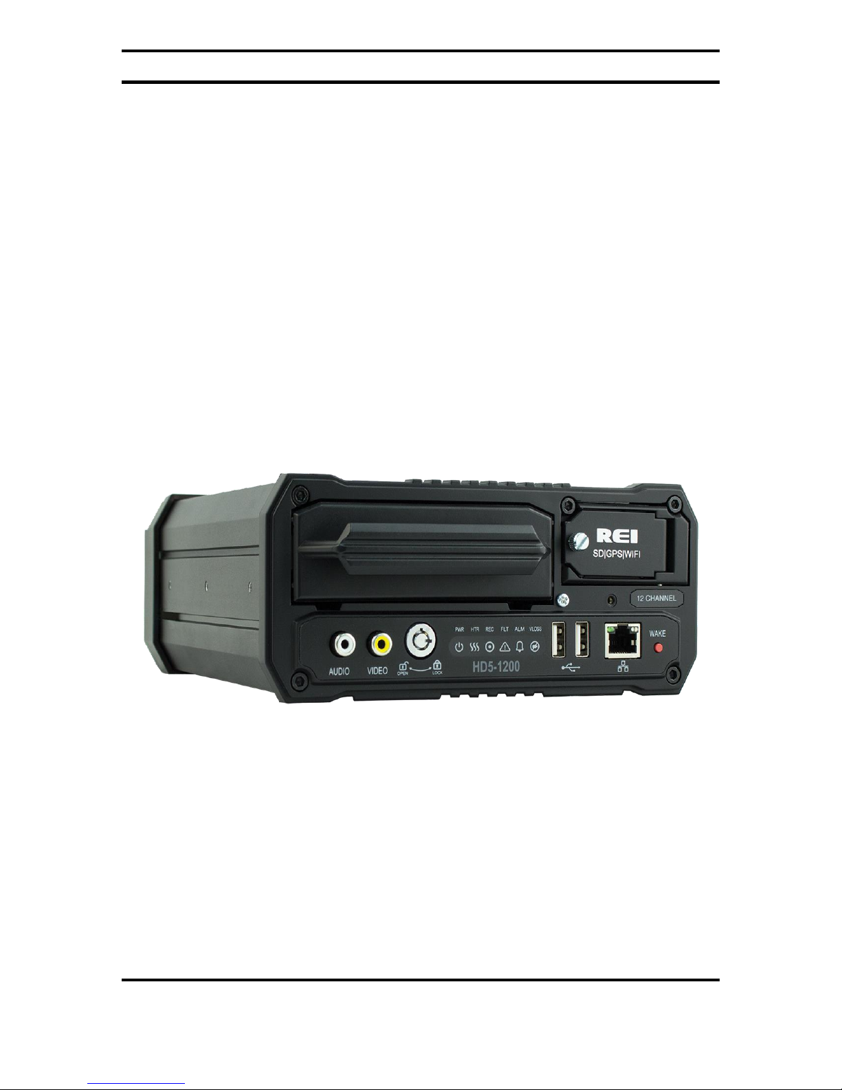
Figure 2: Front Panel Layout............................................................................................ 10
Figure 3: Rear Panel Layout............................................................................................. 11
Figure 4: Removable Hard Drive Module........................................................................ 12
Figure 5: Removable SD Card.......................................................................................... 13
Figure 6: Estimator for HDD Record Times..................................................................... 14
Figure 7: System Wiring - Power and Camera Cables..................................................... 15
Figure 8: External Record Indicator/Event Mark Button Harness Connection................ 16
Figure 9: GPS Antenna Module Harness Connection ...................................................... 17
Figure 10: Vehicle Sensor Options Harness Connection.................................................. 18
Figure 11: Accelerometer Module Harness Connection................................................... 21
Figure 12: 3 Axis Inertia Sensor Directions ..................................................................... 21
Figure 13: L Bracket Mounting ........................................................................................ 22
Figure 14: DVR Dimensions ............................................................................................ 22
Figure 15: Security Cover Mounting................................................................................ 23
Figure 16: Connecting to the DVR with a Computer through the Ethernet Connection.. 25
Figure 17: Main Menu...................................................................................................... 28
Figure 18: Setup Menu...................................................................................................... 28
Figure 19: System Setup Options ..................................................................................... 29
Figure 20: ID Menu .......................................................................................................... 29
Figure 21: Time & Date.................................................................................................... 30
Figure 22: Custom DST Triggers ..................................................................................... 31
Figure 23: Start Up Menu in Ignition Mode..................................................................... 31
Figure 24: Record Schedule Menu ................................................................................... 32
Figure 25: Faults............................................................................................................... 32
Figure 26: Password.......................................................................................................... 33
Figure 27: Video Setup..................................................................................................... 34
Figure 28: Camera –Camera Setup.................................................................................. 35
Figure 29: Custom Record Settings.................................................................................. 35
Figure 30: IPC Setup Pop-up Window ............................................................................. 36
Figure 31: Individual Channel Network Setup................................................................. 37
Figure 32: Alarm Setup..................................................................................................... 37
Figure 33: SD Setup.......................................................................................................... 38
Figure 34: Sub-Stream Setup............................................................................................ 39
Figure 35: Image Setup..................................................................................................... 39
Figure 36: Motion Setup................................................................................................... 40
Figure 37: Motion Setup - Set Grid .................................................................................. 41
Figure 38: OSD Setup....................................................................................................... 41
Figure 39: Input Setup ...................................................................................................... 42
Figure 40: Speed Setup..................................................................................................... 42
Figure 41: Inputs Setup..................................................................................................... 43
Figure 42: Input Setup - Custom....................................................................................... 44
Figure 43: Accelerometer Setup ....................................................................................... 45

HD5 Series Mobile DVR
Page 5 of 59
Radio Engineering Industries, Inc.
640510 -- Rev A –8/29/17
Figure 44: Accel Alarm .................................................................................................... 45
Figure 45: Accelerometer Threshold................................................................................ 46
Figure 46: GPS Port.......................................................................................................... 46
Figure 47: Network Setup................................................................................................. 47
Figure 48: General Network Setup................................................................................... 47
Figure 49: Server............................................................................................................... 48
Figure 50: WIFI Setup...................................................................................................... 49
Figure 51: Cellular Setup.................................................................................................. 50
Figure 52: Route Setup ..................................................................................................... 50
Figure 53: Info Menu........................................................................................................ 51
Figure 54: Camera Tab ..................................................................................................... 51
Figure 55: Inputs Tab........................................................................................................ 51
Figure 56: Alarms Tab...................................................................................................... 52
Figure 57: System Tab...................................................................................................... 52
Figure 58: WAN/Cell Tab ................................................................................................ 53
Figure 59: WIFI Tab......................................................................................................... 53
Figure 60: Versions Tab.................................................................................................... 54
Figure 61: Logs Tab.......................................................................................................... 54
Figure 62: Logs –Search Result....................................................................................... 54
Figure 63: Upgrade Firmware........................................................................................... 55
Figure 64: Export Configuration....................................................................................... 55
Figure 65: Storage Tab...................................................................................................... 55
Figure 66: Live Menu ....................................................................................................... 56
Figure 67: Channel Bar..................................................................................................... 56
Figure 68: Sample Info Data Table................................................................................... 56
Figure 69: Channel Selection Buttons .............................................................................. 57
Figure 70: Playback Menu................................................................................................ 57
Figure 71: Video Tab - Time/Date Search for Date ......................................................... 57
Figure 72: Alarm Tab - Alarm Search.............................................................................. 58

HD5 Series Mobile DVR
Page 6 of 59
Radio Engineering Industries, Inc.
640510 -- Rev A –8/29/17
Introduction
This manual is intended to provide information required for proper installation, initial
setup, and explanation of the individual programming options pertaining to the HD5
Series Mobile DVR surveillance system. For assistance or to answer any questions call:
24 HOUR SERVICE HOT LINE
USA & CANADA
1-877-726-4617 Toll Free
1-402-339-2200
The HD5 is a cost effective, embedded mobile DVR solution supporting up to 6/12 analog
camera inputs. This system features a unique compact rugged design engineered to meet
the demands of harsh mobile environments. The HD5 mobile DVR features the latest
technologies including H.264/MPEG-4 Advanced Video Compression, dual streaming
technology, and all solid-state construction.
Features
●High Definition (1080p) on All Channels
●Ultra HD (4k) Channels 9-12
●GPS
●4G Cellular (optional)
●Fast 802.11n Wi-Fi
●Optional Panic Button
●Full-Frame rate up to 30fps/Channel
●H.264 Triple Streaming
●Optional Accelerometer
●Up to 2TB Hard Drive or optional Solid State Hard Drive
●Up to 256GB SD Card (optional)
●Optional Lockbox
●Extruded aluminum chassis
●Fanless design

HD5 Series Mobile DVR
Page 7 of 59
Radio Engineering Industries, Inc.
640510 -- Rev A –8/29/17
Specifications
Power: 8 to 32 Volts DC, <2A operating (excludes cameras, accessories)
Dimensions: Without brackets: 7.4" x 3.2" x 9.5"; with brackets: 9.1" x 4.0" x
9.5" (max)
Weight: 8.6 lbs. (3.90 kg) with mounting brackets
Standby Current: < 2mA
Operating Temperature: -40°-+160°F continuous operation
Operating Humidity: 10% - 95%, non-condensing
Video Recording
Video Inputs: Up to 12 Channels
Video Standards: NTSC, AHD, ONVIF, REI
Resolution: Up to 1080P Channels 1-8; Up to UHD (4K) Channels 9-12
Frame Rate: Up to 30 fps per channel
Bit Rate: 40 Mbps
Compression: H.264 Triple stream encoding/ recording –high quality recording +
efficient network video streaming
Audio Inputs: 12
Total Channels: 12
Storage
Hard Drive: Removable hard disk drive module with USB 3.0 interface, integrated
shock and vibration dampening, and heater
Expandable Storage: eSATA port for external storage expansion (external HDD) –
up to
16TB of total internal/external storage
SD Card: SD slot for simultaneous (mirror) or alarm video recording
Communication Module
Easily Upgradeable Communication Module: Field or factory installed removable
communication module
WIFI (internal): Optional 802.11a/b/g/n 2.4Ghz/5Ghz Wi-Fi (Wi-Fi models only)
Cellular (internal): Optional 3G/4G modem for cellular connectivity
GPS (internal): Optional internal or external GPS receiver

HD5 Series Mobile DVR
Page 8 of 59
Radio Engineering Industries, Inc.
640510 -- Rev A –8/29/17
Inputs/Outputs
USB ports: Two front panel USB ports for mouse and video backup, firmware
update, configuration, and debugging (log files, etc.)
WAN Ports: Rear panel WAN (Ethernet) port for connection to external 3G/4G
cellular router and for connection to REI and non-REI in-vehicle systems
LAN Ports (IPC, etc.): Front panel LAN port for local DVR configuration, camera
adjustment, IP camera setup, etc.
Front Panel Audio/Video Port: Front panel composite audio/video outputs for local
DVR configuration, camera setup, etc. using a USB mouse
Vehicle Interface (J1939): Dual SAE J1939 250kbps/500kbps interface for
connection to in-vehicle networks, multiplex systems, etc.
Accessory Port (RS485): For connection to optional REI peripherals, including
accelerometer, output modules, display modules, RFID, etc., and non REI devices
GPS/Status Port (RS232): Optional external (RS232) GPS receiver Optional
GPS/Status output (RS232) for interface to third-party AVL systems
Sensor Inputs: Eight sensor inputs for detection of vehicle signals (brakes, turn
signals, etc.)

HD5 Series Mobile DVR
Page 9 of 59
Radio Engineering Industries, Inc.
640510 -- Rev A –8/29/17
System Overview
Figure 1: HD5 Series MDVR System Diagram

HD5 Series Mobile DVR
Page 10 of 59
Radio Engineering Industries, Inc.
640510 -- Rev A –8/29/17
Front and Back Panels
Figure 2: Front Panel Layout

HD5 Series Mobile DVR
Page 11 of 59
Radio Engineering Industries, Inc.
640510 -- Rev A –8/29/17
Figure 3: Rear Panel Layout
Live View
The default view in live view mode using a video monitor connected to the front of the
6/12 channel DVRs displays all channels in matrix view. Left clicking a USB mouse
while in matrix view displays the video from that window into full screen. Left clicking
the mouse returns the display to matrix view.
Initial Set Up
The HD5 Series Mobile DVR system will operate prior to any user setup with the default
settings. However, it may not show the correct time and date (factory set to Central
Standard Time). To set the correct date and time, and program the system operation to your
requirements, refer to the Menu Configuration section of this manual.
When accessing the menu, it is necessary to connect a video monitor to the video jack on
the front or back of the unit. REI recommends using its battery-powered color LCD
monitor P/N 750207.

HD5 Series Mobile DVR
Page 12 of 59
Radio Engineering Industries, Inc.
640510 -- Rev A –8/29/17
Removable HDD and SD Card
DVR Loading and Unloading
Inserting HDD: Turn the HDD key to the unlocked and off position. Slide the HDD into
the DVR and press firmly to make sure it is all the way in. Turn the HDD key to the locked
and on position.
Removing HDD: Turn the HDD key to the unlocked and off position. Grab the handle on
the HDD and carefully pull it out.
Note: The HD5 Series Mobile DVR HD5 series DVR will function even in the absence
of a HDD. Without HDD, DVR will power on and allow the user to configure the
settings, but it will not record any videos unless the user loads the HDD and locks the
HDD key.
Figure 4: Removable Hard Drive Module

HD5 Series Mobile DVR
Page 13 of 59
Radio Engineering Industries, Inc.
640510 -- Rev A –8/29/17
SD Card Loading and Unloading
Inserting SD Card: Open the access door and insert the SD card all the way in until it
locks in place.
Removing SD Card: Push on the SD card all the way in, then release to eject the SD card.
Figure 5: Removable SD Card

HD5 Series Mobile DVR
Page 14 of 59
Radio Engineering Industries, Inc.
640510 -- Rev A –8/29/17
HDD Record Times
To help estimate record times please visit our website www.radioeng.info/rte/hd5.zip.
Figure 6: Estimator for HDD Record Times
Long Term Storage
The HD5 Series Mobile DVR systems draw very little current in stand-by mode. If the
systems are installed, but not used for an extended period of time (i.e., longer than two
weeks) it is recommended that the power be disconnected from the DVR to avoid
draining the vehicle battery. The DVR internal clock will hold the time and date for up
to 10 years sitting on a shelf, and the daylight-saving time functions will resume upon
re-initialization when power is applied.

HD5 Series Mobile DVR
Page 15 of 59
Radio Engineering Industries, Inc.
640510 -- Rev A –8/29/17
Installation
Figure 7: System Wiring - Power and Camera Cables
WARNING
DISCONNECT VEHICLE BATTERY VOLTAGE BEFORE INSTALLING
System WIRING
WARNING
DISCONNECT POWER TO THE DVR BEFORE JUMP STARTING
VEHICLE

HD5 Series Mobile DVR
Page 16 of 59
Radio Engineering Industries, Inc.
640510 -- Rev A –8/29/17
External Record Indicator / Event Mark Button Harness
Figure 8: External Record Indicator/Event Mark Button Harness Connection
The optional external record indicator / event mark button harnesses (Panic Button) are
available with two different types of switches, OEM and aftermarket. The OEM switch is
rectangular and fits into a standard size dashboard knockout. The aftermarket switch is
round, for easier installation in vehicles without spare switch knockouts. Both styles of
switches plug into the same port on the back of the DVR.

HD5 Series Mobile DVR
Page 17 of 59
Radio Engineering Industries, Inc.
640510 -- Rev A –8/29/17
GPS Antenna Module Harness
Figure 9: GPS Antenna Module Harness Connection
The optional DVR GPS antenna module harness plugs into the back of the DVR. This
module will track up to 12 satellites at a time while providing one-second navigation
updates at low power consumption.
The GPS antenna module is housed in a black, water-resistant case and designed to
withstand rugged operating conditions. Information provided to the DVR system includes
longitude, latitude, speed, heading, date, and time. Internal memory backup allows the
GPS antenna module to retain critical data such as satellite orbital parameters, last position,
date, and time to reduce valid data acquisition time.
The 710214 GPS antenna is used for extremely accurate requirements, if the DVR is used
with a lot based Wi-Fi network, it could be more cost effective to use the combination Wi-
Fi/GPS antenna that comes with the higher end DVRs.

HD5 Series Mobile DVR
Page 18 of 59
Radio Engineering Industries, Inc.
640510 -- Rev A –8/29/17
Vehicle Sensor Options Harness
Figure 10: Vehicle Sensor Options Harness Connection
The Vehicle Sensor Options harness connects to various locations in the vehicle to
provide on-screen information regarding vehicle performance. Vehicles have different
sets of signals that can be monitored. Two levels of pre-defined on-screen displays are
available to the installer: SCHOOL BUS and TRANSIT.
The default SCHOOL BUS monitored points in the vehicle are:
•Red warning lamp operation
•Amber warning lamp operation
•Left turn signal
•Right turn signal
•Stop arm lamp operation
•Brake activation
•Front Door
•Rear Door
The default TRANSIT monitored points in the vehicle are:
•Auxiliary 1
•Auxiliary 2
•Left turn signal
•Right turn signal
•Warning lamp operation (de-acceleration lights)
•Brake activation
•Front door switch operation
•Back door switch operation
•Optional point with Auxiliary
Aux inputs are user-
defined and may be
used to monitor
points such as
wheelchair lifts,
inertia sensors, etc.

HD5 Series Mobile DVR
Page 19 of 59
Radio Engineering Industries, Inc.
640510 -- Rev A –8/29/17
Vehicle Sensor Options Harness Vehicle Connections
(Shown as School Bus)
WIRE COLOR
WIRE DESCRIPTION
BLACK
RED WARNING LAMP
BROWN
YELLOW WARNING LAMP
RED
LEFT TURN SIGNAL
ORANGE
RIGHT TURN SIGNAL
YELLOW
STOP ARM
GREEN
BRAKES
BLUE
FRONT DOOR
VIOLET
REAR DOOR
Yellow Warning Lamps
Connect the BROWN wire to the Yellow lamp output of the Warning Lamp
Flasher.
Red Warning Lamps
Connect the BLACK wire to the Red lamp output of the Warning Lamp Flasher.
Stop Arm Lamps
Connect the YELLOW wire to the switched side of the stop arm lamp.
Brake Lamp
Connect the GREEN wire to the switched side of one brake lamp.
Turn Signals
Connect the RED and ORANGE wires to the left and right turn signal lamps.
Front and Back Doors
Connect the BLUE and VIOLET wires to the switched side of the door switches.

HD5 Series Mobile DVR
Page 20 of 59
Radio Engineering Industries, Inc.
640510 -- Rev A –8/29/17
On-Screen Information with Vehicle Sensor Options Harness
The HD5 Series Mobile DVR Surveillance system, when equipped with the HD5 Series
Mobile DVR Option Harness, will display information on-screen in the Installers Mode
when the monitored switches on the vehicle are activated and signals are applied to the
monitored sensors.
ACTIVE SWITCH OR SIGNAL
ON-SCREEN DISPLAY
BRAKE APPLIED
BR
STOP ARM DEPLOYED
SA
YELLOW WARNING LAMPS On
YW
RED WARNING LAMPS On
RW
LEFT TURN SIGNAL On
LT
RIGHT TURN SIGNAL On
RT
FRONT DOOR OPEN
FD
REAR DOOR OPEN
RD
SPEEDOMETER
(SEE NOTE 1)
XX MPH
NOTE 1: The XXs represent the vehicle speed (i.e. 35).
Table of contents
Other Radio Engineering Industries DVR manuals