GVD M3000 Series User manual

www.gvdigital.com
GVD HD NVR Hardware
Quick Installation Guide


Hardware Quick Installation Guide i
Revision history
Revision Time Description
Feb 2016 The M6000 Series changes the motherboard, which involves the following changes
of the product:
M6000 Series no longer supports FBWF but VHD. The following conguration
can be conducted straight without FBWF concern:
■Manage network as described on page 9.
■Manage screen resolutions as described on page 10.
■Manage date, time, & time zone as described on page 11.
By VHD support, system backup and recovery becomes available for M6000
Series:
■Back up initial system state as described on page 17.
■Back up system state as described on page 18.
■Recover system state as described on page 20.
The M6000 Series has the rear I/O ports changed, which involves the following
update in this document.
■Install hardware: M6236, M6036, M6024, M6016, M6012 on page 7is
updated.
May 2016 A brand new NVR M2002 is launched, which involves the following changes of this
document:
Section Install hardware: M2002 is newly added on page 2.
Section Appendix: Install HDDs: M2002 is newly added on page 34.
June 2017
Power-disconnection buzzer is deleted and replaced by a power status LED for
M6236, M6036, M6024, M6016, M6012. See page 7.
The default of RAID initialization state setting for M4006-AR, M4008-AR &
M6000 Series is changed to Full Initialization (Foreground). See page 27.

Hardware Quick Installation Guide
ii
Revision history
May 2018
New products M4106 & M4108 are added:
- Section Install hardware: M4106 & M4108 is added on page 5.
- Appendix. Create RAID5 on M4106, M4108, & M6108 is added on page 29.
- Appendix: Install HDDs: M4106 & M4108 is added on page 42.
M95, M4008, M4008-AR, and M4006-IR are deleted.
June 2018
New product series M6108 is added:
- Section Install Hardware: M6018 is added on page 6.
- Appendix. Create RAID5 on M4106, M4108, & M6108 is added on page 29.
- Appendix: Install HDDs: M6108 is added on page 47.
Sept 2019
Appendix. Create RAID5 : M4106, M4108, & M6108 is updated with the
initialization of "physical device(s)" from step 4to step 8.

Hardware Quick Installation Guide iii
Contents
Revision history .............................................................. i
Contents ........................................................................iii
Hardware requirements.................................................1
Install hardware .............................................................2
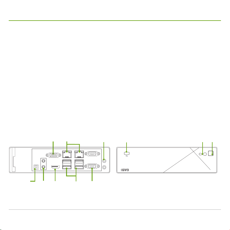
M2002 .......................................................................... 2
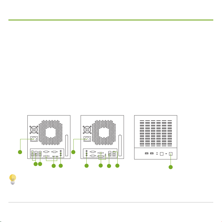
M3000 Series ............................................................... 3
M4006 & M4006-AR..................................................... 4
M4106 & M4108 ........................................................... 5
M6018 .......................................................................... 6
M6236, M6036, M6024, M6016, M6012 ...................... 7
Set up Windows.............................................................8
Manage network............................................................9
Manage screen resolutions .........................................10
Manage date, time, & time zone.................................. 11
Enable watchdog timer................................................12
Initialize HDDs.............................................................13
Create storage volumes ..............................................14
Auto-add a camera......................................................15
Back up initial system state .........................................17
Back up system state ..................................................18
Recover system state..................................................20
Troubleshooting...........................................................22
Appendix. Create RAID5 .............................................24
M3004-IR.................................................................... 24
M4006-AR, M6012, M6016, M6024, M6036, & M623625
M4106, M4108, & M6108 ........................................... 29
Appendix: Install HDDs................................................34
M2002 ........................................................................ 34
M3000 Series ............................................................. 37
M4000 Series ............................................................. 39
M4106 & M4108 ......................................................... 42
M6108 ........................................................................ 47
M6236, M6036, M6024, M6016, M6012 .................... 55
Appendix. Connect S6000 Series to M6236, M6036, M6024,
or M6016 .....................................................................57

Hardware Quick Installation Guide
iv

Hardware Quick Installation Guide 1
Hardware requirements
Recording data is one of the most important parts for video surveillance, and hard disk drives
are one of the most important components to safely store the recording data.
It is always recommended that you use the hard disk drives certified by GVD. Find the list of
the GVD-certified hard disk drives at the link below:
http://www.gvdigital.com/gvdweb/html/document/Support_Lists/Certified%20HDD%20List.pdf
GVD does not guarantee the system performance if a HDD model that is not certied by
GVD is used.
GVD always recommends the use of Enterprise Class SATA hard drives for GVD Enterprise
NVR, Failover Server, Backup Server, Extended Storage because it supports TLER (Time
Limited Error Recovery), higher MTBF, higher Duty Cycles and typically include a sensor
for rotation and vibration.

Hardware Quick Installation Guide
2
Install hardware: M2002
1 Connect the keyboard and mouse to the USB ports or the PS/2 ports.
2 Connect the display monitor to either the VGA port or the HDMI port.
3 Plug in a CAT-6 UTP cable to the RJ-45 Gigabit LAN port, and connect the other
end of the cable to a switch connecting to the camera network.
4 Plug in the speaker to the audio output port if necessary.
5 Connect the power cable (with the power adapter) to the DC-in power jack. Then
connect them to a power outlet.
6 The NVR then auto powers on when power source is connected.
7 The LED lights blue when the NVR powers on.
8 If serial data connection is needed, connect cables to these serial COM ports.
9 Hit this power button to power on the system.
➊➋
➋ ➌
➎ ➊
➍
➑
➊ ➒➐

Hardware Quick Installation Guide 3
Install hardware: M3000 Series
1 Connect the keyboard and mouse:
- M3004: Connect them to the USB ports.
- M3004-IR: Connect the mouse to one of the USB ports and connect the keyboard to
one of the USB ports or to the purple PS/2 connector.
2 Connect the display monitor to either the D-sub or DVI or HDMI port.
3 Connect the power cord to the AC power socket at the rear panel of the unit.
4 Plug in a CAT-6 UTP cable to the RJ-45 Gigabit LAN port, and connect the other
end of the cable to a switch that is connected to camera network.
5 Plug in the speaker to the audio output port if necessary.
6 The unit then auto powers on when the power cord is connected to power source.
6
1
3
4
52
4
1
3
5
2
Rear: M3004-IR Rear: M3004 Front
GVD isn’t responsible for any system malfunction if a 3rd-party application that isn’t certied by
GVD is installed in the system.
M3004 (IR) series support decoding the resolution from D1 up to 20M.
DO NOT plug any USB device except keyboard & mouse before the operating system starts.

Hardware Quick Installation Guide
4
Install hardware: M4006 & M4006-AR
1 Connect a keyboard to one of the USB ports.
2 Connect a mouse to one of the USB ports.
3 Connect a display monitor to either the D-sub or DVI or HDMI port.
4 Connect the power cord to the AC power socket.
5 Plug in a CAT-6 UTP cable to the RJ-45 Gigabit LAN port, and connect the other
end of the cable to a switch connecting to the camera network.
6 Plug in the speaker to the audio output port if necessary.
7 Hit the power button to power on the NVR.
1
623
4
57
GVD isn’t responsible for any system malfunction if a 3rd-party application that isn’t certied by
GVD is installed in the system.
M4006 and M4006-AR support decoding the resolution from D1 up to 20M.
DO NOT plug any USB device except keyboard & mouse before the operating system starts.
M4106 & M4108

Hardware Quick Installation Guide 5
Install hardware: M4106 & M4108
M4106 & M4108
1 Connect a keyboard to one of the USB ports.
2 Connect a mouse to one of the USB ports.
3 Connect one or more display monitors to the D-sub, DisplayPort, DVI or HDMI
ports.
4 Connect the power cord to the AC power socket .
5 Plug in a CAT-6 UTP cable to the RJ-45 Gigabit LAN port, and connect the other
end of the cable to a switch connecting to the camera network.
6 Plug in the speaker to the audio output port if necessary.
7 Hit the power button to power on the NVR.
2
3
4
5
716
GVD isn’t responsible for any system malfunction if a 3rd-party application that isn’t certied by
GVD is installed in the system.
The M41-Series support decoding the resolution from D1 to 20M.
DO NOT plug any USB device except keyboard & mouse before the operating system starts.

Hardware Quick Installation Guide
6
Install hardware: M6108
1 Connect a keyboard to one of the USB ports.
2 Connect a mouse to one of the USB ports.
3 Connect one or more display monitors to the VGA, DVI, HDMI, or DisplayPort port.
4 Connect the power cord to the AC power socket .
5 Plug in a CAT-6 UTP cable to one of the RJ-45 Gigabit LAN ports, and connect
the other end of the cable to a switch connecting to the network of your camera
channels.
6 Plug in the speaker to the audio output port if necessary.
7 Hit the power button to power on the NVR.
1
2
5
73
4
6
GVD isn’t responsible for any system malfunction if a 3rd-party application that isn’t certied by
GVD is installed in the system.
The M6108 supports decoding the resolution from D1 to 20M.
DO NOT plug any USB device except keyboard & mouse before the operating system starts.

Hardware Quick Installation Guide 7
Install hardware: M6236, M6036, M6024, M6016, M6012
1 Connect your keyboard and mouse
to the USB ports. (Note USB 3.0
ports only work in Windows O.S.)
2 Connect one or more monitors to the
VGA ports, HDMI port or DVI-D port.
3 Plug an RJ-45 cable to one of the
LAN ports (one with IPMI support),
and connect the other end of the
cable to a network switch that your
IP cameras connect to.
4 Connect power cords to both of the
power units.
5 The power status LED auto lights
when the system turns on once
power is connected.
6 This is an SAS connector. Connect
an S6000 Series unit to extend
storage.
GVD isn’t responsible for any system
malfunction if a 3rd-party application that
isn’t certied by GVD is installed in the
system.
M6000 series support decoding resolution
from D1 up to 20M.
DO NOT plug any USB device except
keyboard/mouse before OS startup.
6
12
3
IPMI LAN
42
USB3.0 USB2.0
5
Serial COM port
6
12
3
IPMI LAN
42
USB3.0 USB2.0
5
Serial COM port
Facility Description
Button
Power
Turns on/off the system.
• This button cuts off main power
supply while remaining standby
power. To maintain the system,
disconnect the system from power
source.
Reset Restarts the system.
Status
LED
Power Lights when power is connected.
HDD Blinks when HDD is being accessed.
NIC# Blinks when network data connection
is active.
PWR Disconn. Lights when one of the power units
isn't connected to power source.
Information
Lights when one of these conditions
meets: 1. system overheat, 2. fan
failure, 3. power failure, 4. local UID
on, and 5. remote UID on.

Hardware Quick Installation Guide
8
Set up Windows®
When the NVR system starts for the first time, a Set Up Windows wizard opens onscreen.
Follow the guide below to go through the setup.
1 Select the display language for the operating system.
2 Click the Next button to proceed.
3 Congure the regonal settings to meet your locale.
4 Click the Next button to proceed.
5 Manage the date, time and time zone to meet your
locale.
6 Click the Next button to proceed.
It takes a few moments for the wizard to nalize the
settings. Once the nalization is through, the system auto-restarts to apply the
change.
1
2
3
4
6
5

Hardware Quick Installation Guide 9
Manage network
1 Click Windows®Start button | Control Panel | Network and Sharing Center |
Change adapter settings.
2 Right-click over the active connection and click Properties from the context menu
that opens.
3 Click Internet Protocol Version 4 (TCP/IPv4). Then click the Properties button.
4 On the General tabbed page, congure the IP address and the subnet mask. Then
hit the OK button.
Before conducting the network conguration, get the network environment ready. If the network is
not available, contact your network administrator for further help.

Hardware Quick Installation Guide
10
Manage screen resolutions
1 Click Windows®Start button | Control Panel | Display | Adjust resolution.
2 Change the Screen resolution to 1680 x 1050 ( the recommend value).
2
The minimum screen
resolution supported is 1280
x 1024.
3 Hit the OK button to save the change.
For some models that support dual-monitor, visit the link below for the setup:
http://www.gvdigital.com/gvdweb/html/document/Support_Lists/Dual%20Monitor%20Setup.pdf

Hardware Quick Installation Guide 11
Manage date, time, & time zone
1 Click Windows®Start button | Control Panel | Date & Time | Change Time Zone.
2 Set the correct time zone and apply the change.
3 Click Internet Time tab and click the Change settings button.
4 It is recommended that you sync the time with an internal NTP (Network Time
Protocol) server installed in your network. However If you don't have one, select
Synchronize with an Internet time server and select a server from the Server
drop-downs. Then click the Update now button to synchronize the time. If you
have neither an internal NTP server nor Internet connection, deselect Synchronize
with an Internet time server.
1
2
3
4
5
5 Hit the OK button to quit the setting.

Hardware Quick Installation Guide
12
Enable watchdog timer
This section is for M3004-IR only.
After you are done with the Windows setup covering the display language setting, the regional
setting, and the date/time/time-zone settings, proceed to enable the watchdog timer for the
NVR. Follow the guide below to go through the procedure:
1 Restart the NVR.
2 Upon seeing the Power On Self Test onscreen, continuously hit the Delete key.
The Power On Self Test screen
The BIOS Setup utility then opens onscreen.
3 Open the menu Conguration | Super I/O
Conguration.
4 On the Super I/O Conguration menu,
select Watch dog timer.
5 From the options that show, select Enabled
in second unit.
6 Continue to select Watch dog timer counter.
7 From the options that show, select 60.
8 Open the menu Save & Exit. On the menu,
select Save Changes and Reset.
The utility then saves the change and quits.

Hardware Quick Installation Guide 13
Initialize HDDs
A newly added Hard Disk needs to be initialized before a volume can be created.
However, before an HDD can be initialized, RAID5 must be created rst. See page 24 for the RAID5
creation for M3004-IR, page 25 for M4006-AR, M6012, M6016, M6024, M6036, & M6236, and page
29 for M4106, M4108, & M6108.
1 Click Windows®Start button.
2 From the Start menu that opens, right-click on Computer.
3 From the context menu that opens,
click Manage.
4 Click the Storage plus sign (+) to drop down the list. Then click Disk Management from the
drop-downs.
5 Right-click on a “Non Initialized” HDDs and then click Initialize Disk.
6 Select the HDD(s) to initialize and then click the OK button.
7 When the initialization is through, the selected HDDs will display “Online” status.
For HDD size more than
2TB, select GPT instead of
MBR when initializing.

Hardware Quick Installation Guide
14
Create storage volumes
1 From Windows®Desktop, double-click the Storage Conguration Manager
icon.
2 When asked to log in, enter the default username Admin and password 6001.
3 In the SCM that opens, hit the plus sign (+) button from the left pane.
4 When asked how to add a storage volume, click Using HD.
5 In the Volume Name eld, enter a name for the volume you are creating.
6 From the Available Hard Disks box, click the hard disk(s) to add. Then, click the
doubled right-arrow button
to advance the selected hard
disk(s) to the Hard Disk Drives
in Volume box.
7 Click the Add to List button to
add the selected hard disks to
queue for formatting.
8 Click the Create button to
continue.
9 The system then shows a
message – ‘Create Volume
will reallocate your hard disk
and erase the current data on
the disk. Are you sure to keep
doing these jobs?’ Click Yes to
continue.
This manual suits for next models
11
Table of contents
Other GVD DVR manuals