GVD M1184 User manual

GVD Mobile NVRs
M1184 & M1284
Quick Start Guide


Mobile NVRs M1184 / M1284 Quick Start Guide i
Contents
Contents ....................................................................... i
Preface .........................................................................ii
About this Document ......................................................... ii
Declaration of Conformity.................................................. ii
Copyright and Trademarks ................................................ ii
Hardware Requirements..............................................iii
Introduction.................................................................. 1
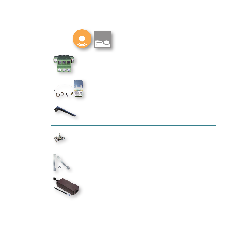
Accessories ................................................................. 2
Take a Tour .................................................................. 4
Front-Right View................................................................4
Rear-left View: M1184 .......................................................7
Rear-left View: M1284.......................................................9
Install Hardware..........................................................11
Access Motherboard ....................................................... 11
Install a WiFi Module .......................................................13
Install a 3G or 4G plus GPS Module (Optional) ..............16
Install a SIM Card............................................................19
Install Internal SATA HDDs/SSDs....................................20
Install Outside-accessible SATA HDD/SSD.....................22
Mount the Mobile NVR .............................................. 23
Wire DC-in Power Source ......................................... 24
Manage Ignition Power.............................................. 26
Wire Ignition Signal .........................................................26
Select Ignition Power Mode.............................................27
Set up Windows®...................................................... 28
Initialize HDDs........................................................... 29
Launch & Log in......................................................... 30
Use Initialization Wizard ............................................ 31
Congure Network Parameters ................................. 38
Create Storage Volumes ........................................... 39
Auto-add a Camera ................................................... 40
Appendix. Install 3G/4G Device Driver & Connect
Mobile Network for the 1st Time ................................ 42
Appendix. Install WiFi Device Driver & Connect WiFi
Network for the 1st Time............................................ 45

Mobile NVRs M1184 / M1284 Quick Start Guide
ii
Preface
About this Document
This document is meant for the experienced users and integrators with hardware knowledge of personal computers.
If you are not sure about the description herein, consult your vendor before further handling. We recommend that you
keep one copy of this document for the quick reference for any necessary maintenance in the future. Thank you for
choosing GVD products.
Declaration of Conformity
FCC
This equipment has been tested and found to comply with the limits for a Class A digital device, pursuant to part 15
of the FCC Rules. These limits are designed to provide reasonable protection against harmful interference when the
equipment is operated in a commercial environment. This equipment generates, uses, and can radiate radio frequency
energy and, if not installed and used in accordance with the instruction manual, may cause harmful interference to radio
communications. Operation of this equipment in a residential area is likely to cause harmful interference in which case
the user will be required to correct the interference at his own expense.
CE
The product(s) described in this manual complies with all applicable European Union (CE) directives if it has a CE
marking. For computer systems to remain CE compliant, only CE-compliant parts may be used. Maintaining CE
compliance also requires proper cable and cabling techniques.
Copyright and Trademarks
This document contains proprietary information protected by copyright. All rights are reserved. No part of this document
may be reproduced by any mechanical, electronic, or other means in any form without prior written permission of the
manufacturer. Company/product names mentioned herein are used for identification purposes only and are trademarks
and/or registered trademarks of their respective companies.

Mobile NVRs M1184 / M1284 Quick Start Guide iii
Hardware Requirements
Recording data is one of the most important parts for video surveillance, and hard disk drives are one of
the most important components to safely store the recording data.
It is always recommended that you use the hard disk drives certified by GVD. Find the list of the GVD-
certified hard disk drives at the link below:
http://www.gvdigital.com/gvdweb/html/document/Support_Lists/Certified%20HDD%20List.pdf
NOTE:
* GVD does not guarantee the system performance if a HDD model that is not certified by GVD is used.
* GVD recommends that you always use enterprise-level SATA hard drives for GVD enterprise NVR, Failover Server, Backup Server,
Extended Storage because it supports TLER (Time Limited Error Recovery), higher MTBF, higher Duty Cycles and typically include a
sensor for rotation and vibration.

Mobile NVRs M1184 / M1284 Quick Start Guide
iv

Mobile NVRs M1184 / M1284 Quick Start Guide 1
Introduction
Thank you for choosing GVD products. The M1184 and M1284 are the
heavyweights of GVD's M1 Series, the brand new line of mobile NVRs.
Powered by Intel®Core™ i5-3610ME, M1184 and M1284 are capable of
high performance and low power consumption. The integrated Intel®HD
(4000) Graphics that brings DirectX 11 also allows the NVRs to deliver
superb video and audio.
The M1184 and M1284 come with a WiFi module. If you opt for a 3G or
4G (plus GPS) module to go inside the mobile NVR, the mobile NVR can
stay constantly connected with the control center. And the intelligent power
management can prevent startup failure and allow the control center to
watch over the car battery usage through 3G/4G or WiFi. Isolated DIO on
the other hand keeps the mobile NVR connected with other in-vehicle devices such as a car door sensor
so the change of DIO states can be sent to the control center.
If you opt for a GPS (plus 3G or 4G) module to go inside the mobile NVR,
the control center can instantly locate the vehicle that carries the mobile
NVR on the map. Also on option is a G-sensor to measure the vibration
every couple of minutes and feed the data back to the control center. On the
other hand the mobile NVR is verified
to be anti-shock and anti-vibration to
guarantee more protection to the hard
disk drives onboard and ensures non-stop video recording.
Rugged and sealed M12 connectors are featured on the PoE LAN ports
of M1284. These connectors withstand harsh-industrial and weather
environments and ensure reliable connections in the vehicles and trains
that are moving. And the modular mechanical design also makes these
NVRs easy-to-install and maintain.
The simple and sturdy design makes the M1184 and M1284 ideal
for all kinds of transportation. They are your best choice for IP video
surveillance on the go.
Product Highlights
• Power over Ethernet
• M12 PoE LAN ports
• Built in GPS Receiver
• Built-in G-sensor
• Anti-shock / anti-vibration
• Rich data connections
• Easy-swappable storage
• Intelligent power management
• Isolated DIO

Mobile NVRs M1184 / M1284 Quick Start Guide
2
Accessories
Driver CD & User's Manual
DRIVERS
User’s
Manual
Terminal Block
1 x 3-pin male terminal block for 8~35VDC output
WiFi Module Kit
SparkLAN WPER-172GN 802.11b/g/n USB Half Mini Card
■802.11b/g/n ISM Band: 2.400 ~ 2.4835GHz
■Antenna: 2 x U.FL connectors (diversity antenna), 1T1R
1 x External Antenna
■RP-SMA male body & female inner contact
A few screws to x the module
■stainless-steel round philips screws
Wall-mount Kit
■2 wall-mount brackets
■Four M3 P-Head screws
Power Adapter
(Optional)
24V/6.67A 160W AC/DC adapter
(for +8~35VDC output)

Mobile NVRs M1184 / M1284 Quick Start Guide 3
Accessories
Region Module (w/ GPS capability) & Wire External Antenna
4G+GPS
Module Kit
(Optional)
Southeast Asia,
Middle East &
partly India (1800
MHz only)
Sierra Wireless® AirPrime™
MC7304 w/ 15cm internal wire
■LTE-FDD / HSPA+ (B1, B2, B3, B5,
B7, B8, B20)
1 x 3G or 4G External
Antenna
■RP-SMA male body &
male inner contact
1 x GPS External
Antenna
■Length: 300cm
■RP-SMA male body &
male inner contact
A few screws to x the
module
■Stainless-steel round
philips screws
North America &
Latin America
Sierra Wireless® AirPrime™
MC7354 w/ 15cm internal wire
■LTE-FDD, HSPA+, GSM/GPRS/
EDGE, GSM/GPRS/EDGE, CDMA
(B1, B2, B4, B5, B8, B13, B17, B25,
BC0, BC1, BC10)
3G+GPS
Module Kit
(Optional)
All regions
HUAWEI MU609 Mini-PCIe
■HSPA+/UMTS quad-band
850/900/1900/2100 MHz
■GSM/GPRS quad-band
850/900/1800/1900 MHz
Sierra Wireless® AirPrime™
MC8705 w/ 15cm internal wire
■Operational bands: WCDMA 850,
WCDMA 900, WCDMA 1900,
WCDMA 2100

Mobile NVRs M1184 / M1284 Quick Start Guide
4
Take a Tour
CFast
card
socket
On/Off
Control
& Status
Output
Status
LEDs
Power
button
DB-15 video
connector
PS/2
keyboard
mouse port
Ethernet
LAN port
USB 3.0
ports
DVI-I
video port
USB 2.0
ports
Mic-in &
Line-out SATA
HDD/
SSD
trays
Reset
button
Cutout
holes
DVI-D
video port
Title Description
SATA HDD/SSD
trays
Two outside accessible slide-trays to install two SATA HDDs/SSDs.
Available are the other two SATA HDD/SSD sockets inside the mobile NVR. See also Install
Internal SATA HDDs/SSDs on page 20.
Reset button
Restarts the system without turning off the power.
To prevent false trigger, this button is recessed in the panel. Use an object with a pointed end to hit
this button.
Cutout holes Two cutout holes for antenna-wired SMA connectors to join external antennas.
Power button
Turns on/off the system. Hit this button to turn on the system. Hit this button again to power off the
system. Hit-and-hold this button to force system shutdown.
There must be no less than 5 seconds between each power on/off.
The power button lights blue when the system is powered on.
Front-Right View

Mobile NVRs M1184 / M1284 Quick Start Guide 5
Take a Tour
Title Description
Status LEDs
Deliver the states of some system parts:
Printed Text Color Description
HDD Red Lights when the SATA HDD is being accessed.
WDT Yellow Blinks when the watchdog timer is started.
IGN Green Lights when ignition signal is received.
CFast card
socket
Provides a socket for the portable storage device of CFast, which is an interface with similar form
factor with CompactFlash but leveraging serial ATA interface to offer higher data transfer rate.
The socket here is a push-push type. Push-insert a CFast card to install it and push-eject to
remove the CFast card.
PS/2 keyboar /
mouse port
Connector for a legacy keyboard / mouse.
Use an Y-cable to connect a PS/2 keyboard / mouse.
Implemented with industrial-grade ITE8783 Super IO chip (-40 to 85°C).
Ethernet LAN
port
One Gigabit Ethernet port with Intel®82579LM controller, with status LEDs.
Supports Intel®AMT (Active Management Technology) for the advanced features such as SOL
(serial-over-LAN) and remote on/off control.
The status LEDs deliver the follow states:
LED Color State Description
LINK/ACT Yellow
Off Disconnected
On Connected with no data transmission
Blinking Connected with active data transmission.
SPEED Green Off The data transmission speed reaches 10Mbps.
On The data transmission speed reaches 100Mbps.
Orange On The data transmission speed reaches 1000Mbps.
DB-15 video
connector
Connector for an external VGA monitor or projector.
Supports up to 2048 x 1536 resolution.
Mic-in &
Line-out
Microphone input (pink) and speaker out (green).
Implemented with Intel®High Denition Audio and Realtek®ALC262 codec.
Install appropriate drivers to make the device work.

Mobile NVRs M1184 / M1284 Quick Start Guide
6
Take a Tour
Title Description
On/off Control
and Status
Output
Connector for an additional on/off switch and additional status LEDs to the mobile NVR, which will be
very helpful when the mobile NVR is installed inside a cabinet.
Pin denition:
Pin Denition Description 1
2
9
10
1Ctrl+ [Input] Remote on/off control.
Should be connected to an external switch to turn
on/off the system (polarity is negligible).
2Ctrl-
3Power+ [Output] Status LED for system power.
Lights when the system is turned on. Off when the
system is turned off.
4Power-
5HDD+ [Output] Status LED for hard disk drive activity.
Blinks when the SATA disk drive is being
accessed.
6HDD-
7IGN+ [Output] Status LED for ignition signal.
Lights when ignition signals are received.
8IGN-
9WDT+ [Output] Status LED for watchdog timer.
Blinks when the watchdog timer is started.
10 WDT-
* Make sure the polarity is correct when connecting the external status LED to the status LED outputs.
USB 3.0 ports
Two USB 3.0 ports with xHCI (eXtensible Host Control Interface) by default that support the devices of
USB 3.0, USB 2.0, USB 1.1 and USB 1.0.
Legacy USB is supported so USB keyboard/mouse are able to work in DOS.
Install USB 3.0 driver to be able to use USB 3.0 in Windows 7.
* Intel®USB 3.0 driver doesn't support Windows XP. All USB 3.0 ports will work as USB 2.0 ports in Windows XP.
DVI-D &
DVI-I video
connectors
Connectors for external montiors with DVI interface.
Support up to 1920 x 1200 resolution.
Support HDMI if an DVI-to-HDMI cable is provided.
USB 2.0 ports
Two USB 2.0 ports with EHCI (Enhanced Host Control Interface) by default that support the devices of
USB 2.0, USB 1.1 and USB 1.0.
Legacy USB is supported, which means USB keyboard/mouse still work in DOS.

Mobile NVRs M1184 / M1284 Quick Start Guide 7
Take a Tour
Rear-left View: M1184
COM1
DC-in
power
jack
COM2
SATA HDD/
SSD trays
Antenna
cutout
holes
PoE LAN
port
Title Description
DC-in power jack
3-pin power jack accepting wide-range DC power in from 8V to 35V, with ignition control.
Pinout: Pin# Def. Description
1V+ Positive polarity of DC power input
from 8V~35V.
2GND Gound of DC-in power.
3IGN Ignition signal input, e.g. the ACC
power of vehicles
1
Make sure the voltage of your DC-in power source is between 8V to 35V before tapping it.
Tapping p0ower source over 35V will damage the system.
The ignition input accepts the 12VDC ACC power of a car or 24VDC ACC power of a bus/
truck. Supplying power over 35V to ignition will damage the system.

Mobile NVRs M1184 / M1284 Quick Start Guide
8
Take a Tour
Title Description
COM1 & COM2
Two serial COM ports.
Both support RS232, RS422 and RS485, user-denable at the BIOS Setup | Advanced
menu | Peripheral Conguration.
Implemented with industrial-grade ITE8783 Super IO chip (-40 to 85°C) and up to 115200
bps data transfer rate.
Pinout: Pin# RS232 RS422 (Two-wire) RS485
1DCD
2RX 422 TXD+ 485 TXD+/RXD+
3TX 422 RXD+
4DTR 422 RXD-
5GND GND GND
6DSR
7RTS
8CTS 422 TXD- 485 TXD-/RXD-
9RI
5
1
6
9
PoE LAN ports
Pin 1 Pin 8
Speed LINK/ACT
8 Power-over-Ethernet LAN ports that feature the following:
Delivering up to 25.5 W (80W total budget).
When only one of the four ports is occupied, a maximal 1000 MB/s bandwidth is
achievable. When all four ports are connected, all devices share 1000 MB/s bandwidth (i.e.
250 MB/s if all four devices run simultaneously).
The status LEDs deliver the follow states:
LED Color State Description
LINK/ACT/SPEED Orange
Off The data transmission speed reaches 10Mbps.
On The data transmission speed reaches 100/1000Mbps.
Blinking Connected, with active data transmission.
Antenna cutout holes Two cutout holes for antenna-wired SMA connectors to join external antennas.
SATA HDD/SSD trays
Two outside accessible slide-trays to install two SATA SSDs/HDDs.
Available are the other two SATA HDD/SSD sockets inside the mobile NVR. See also
Install Internal SATA HDDs/SSDs on page 20.

Mobile NVRs M1184 / M1284 Quick Start Guide 9
Take a Tour
Rear-left View: M1284
COM1
DC-in
power
jack
SATA HDD/
SSD trays
Antenna
cutout
holes
M12 PoE
LAN ports
Title Description
DC-in power jack
3-pin power jack accepting wide-range DC power in from 8V to 35V, with ignition control.
Pinout: Pin# Def. Description
1V+ Positive polarity of DC power input
from 8V~35V.
2GND Gound of DC-in power.
3IGN Ignition signal input, e.g. the ACC
power of vehicles
1
Make sure the voltage of your DC-in power source is between 8V to 35V before tapping it.
Tapping p0ower source over 35V will damage the system.
The ignition input accepts the 12VDC ACC power of a car or 24VDC ACC power of a bus/
truck. Supplying power over 35V to ignition will damage the system.

Mobile NVRs M1184 / M1284 Quick Start Guide
10
Take a Tour
Title Description
COM1
One serial COM port.
Supports RS232, RS422 and RS485, user-denable at the BIOS Setup | Advanced menu
| Peripheral Conguration.
Implemented with industrial-grade ITE8783 Super IO chip (-40 to 85°C) and up to 115200
bps data transfer rate.
Pinout: Pin# RS232 RS422 (Two-wire) RS485
1DCD
2RX 422 TXD+ 485 TXD+/RXD+
3TX 422 RXD+
4DTR 422 RXD-
5GND GND GND
6DSR
7RTS
8CTS 422 TXD- 485 TXD-/RXD-
9RI
5
1
6
9
M12 PoE LAN ports
8 Power-over-Ethernet LAN ports with M12 connectors that feature the following:
M12 A-codig 4A 4P female connector
Delivering up to 25.5 W (80W total budget).
Pinout: M12
Pin
RJ45
Pin
Description
Fast
Ethernet
Gigabit
Ethernet
1 6 RX- DB-
2 2 TX- DA-
3 1 TX+ DA+
4 3 RX+ DB+
Antenna cutout holes Two cutout holes for antenna-wired SMA connectors to join external antennas.
SATA HDD/SSD trays
Two outside accessible slide-trays to install two SATA SSDs/HDDs.
Available are the other two SATA HDD/SSD sockets inside the mobile NVR. See also
Install Internal SATA HDDs/SSDs on page 20.

Mobile NVRs M1184 / M1284 Quick Start Guide 11
Access Motherboard
M1284
In order to install hardware or maintain the mobile NVR, you often have to open the mobile NVR and
further access the motherboard. The mobile NVR features modular mechanical design to facilitate the
work. Follow the guide below to open the mobile NVR and access the motherboard.
1. Place the mobile NVR on a at and soft surface. Find the SATA storage tray knobs perching on one
side of the mobile NVR. First loosen the knobs and then slide out and fully remove the trays from the
mobile NVR.
2. Use a hex wrench to loosen and remove the screws as marked in the illustration below. Then
dismantle the bottom, front and rear panels from the mobile NVR.
M1184

Mobile NVRs M1184 / M1284 Quick Start Guide
12
Access Motherboard
Note
For M1284 mobile NVR, be sure to disconnect the
DC-in terminal block before you can completely
part the rear panel from the mobile NVR.
Disconnect the DC-in
terminal block.
The inside of the mobile NVR then comes to
view.
3. Loosen and remove the four M3 F-head screws
as marked in the illustration below. Then
dismantle the SATA storage bracket.
The top side of the motherboard comes to
view.

Mobile NVRs M1184 / M1284 Quick Start Guide 13
Install a WiFi Module
The mobile NVR comes with two PCI Express Mini Card sockets to carry a wireless module for data
connection or as a radio receiver. Follow the guide below to install a WiFi module to the mobile NVR:
1. Open the mobile NVR and access the motherboard as
described in Access Motherboard on page 11.
The motherboard then comes to view.
2. Find the two PCIe Mini Card sockets on the motherboard.
Note to install the WiFi module at the socket without a SIM
card holder.
The connector has a break
among the contact pins.
Connector’s break
Mini-Card socket
socket for a WiFi module or
some other wireless module
socket for a
4G module
3. Have the WiFi module from
the accessories. The module
is a half-size module of PCIe
Mini Card, with two U.FL
connectors.
4. In order to make
the half-size WiFi
module compatible
with the Mini Card
socket, extend the
WiFi module with a
“mini half bracket”.
Join them together
by using two
screws.
Two U.FL connectors
5. Plug the Wi-Fi module to
the socket’s connector by a
slanted angle. Fully plug the
module, and note the notch
on the wireless module
should meet the break of the
connector.

Mobile NVRs M1184 / M1284 Quick Start Guide
14
Install a WiFi Module
6. Press down and x the
module in place by
fastening two screws.
Press
8. See the pictures below. Remove
the plastic plug exactly as the
picture below shows from the
front panel to open a hole for the
WiFi antenna. Keep the plastic
plug for necessary restoration in
the future.
Open a hole for the WiFi
antenna.
7. Have the antenna wire that
goes with the module. Connect
the antenna wire to the U.FL
connector exactly as illustrated
below.
Connect the antenna wire
to the the U.FL connector
exactly as shown.
9. Pull the other end of the
antenna wire, a SMA
connector jack, through
the antenna hole. Be sure
to meet the at side of the
SMA jack with the at side
of the antenna hole so the
connector jack won't get
stuck.
Arrange the at side of the
SMA connector to meet the
at side of the antenna hole.
Note See the recommended antenna
wire layout as illustrated below.
It is recommended that the WiFi
antenna be pulled through an
antenna hole at the front panel.
WiFi
WiFi
3G/
4G+
GPS
GPS 3G or 4G
WiFi antenna to be pulled
through an antenna hole at
the front panel.
This manual suits for next models
1
Table of contents
Other GVD DVR manuals