Hafco GHD-50 User manual

INSTRUCTION MANUAL
GHD-50
Geared Head Drill (415V)
50mm Drilling Capacity with Automatic
Feed & Tapping 4MT
D178
Page 1
Instruction Manual for GHD-50 (D178)
23/12/2014

Operation Manual Total 1
page 1
Contents
1. Main use and features of the machine
2. Main technical data
3. Brief des
cription of the driving system and its structure
4. Electrical system
5. Lubrication and coolant system
6. Hoisting and installation
7. Use and operation of the machine
8. Machine adjustment
9. Machine use and maintenance
10. Machine accessories
Page 2
Instruction Manual for GHD-50 (D178)
23/12/2014

Operation Manual Total 26
page 1
Dear end-user,
Thank you very much for choosing our products. Please let us have the model of your machine,
series number, as well as the name, address and correspondence method of your company in
order to facilitate us to let you have a good service.
Important notice:
1. Please immediately contact your dealer in case the machine, accessories or documents are
not in conformity with those indicated in the packing list after the machine package is
opened.
2. Please carefully read this Operation Manual particularly the electric part of this documents
before installation, testing and running the machine.
3. Removing grease on the machine (particularly on the column) and checking lubrication oil
in each place is well filled . Running the machine without lubrication oil is strictly
forbidden. Lubrication of the machine as per the stipulation of this documents is required.
4. Ground wire of the machine shall be well connected. When test running, push jog button in
slow spindle speed to check if direction of spindle revolution is correct.
5. Machine must be stopped if spindle speed or feed rate change is necessary.
6. Please check if cutting tool or work piece is well clamped before machining
7.
The red mushroom push button located in front of the spindle box is an emergence push
button for emergency purpose only. Familiar with its position and its use are necessary.
8. Professional electric service engineer is required for electric maintenance.
9. The machine must be stopped when you need removing away the cutting material around the
drill. Moving the cutting material by hand or by hook is definitely forbidden.
10. Correct use and daily maintenance of the machine are required in order to keep machine
accuracy and its lifetime in long time.
11. We will much appreciate if you could solve some problems of the machine.
In order to facilitate us for the service, please let us know the details regarding the places and
phenomenon of the troubles if you could not solve problems.
Page 3
Instruction Manual for GHD-50 (D178)
23/12/2014

Operation Manual Total 26
page 2
1.Main use and features of the machine:
GHD-50 series vertical drilling machines are our new products designed and
developed by our-self based on our accumulated experience in so many years in this
field. It is a light, column type, superior quality and high efficiency machine with
milling function vertical drilling machine. It is really a multi-function universal machine
which could be widely used for small and middle sizes of work pieces for drilling, spot
facing, reaming, tapping and milling etc. Besides, some machine tool accessories could
also be used on this machine. The machines are suitable for the machining workshop,
maintenance workshop and production line etc.
Features:
1.1
Good in appearance, easy in operation, convenience in maintenance and well
consideration in safety protection
1.2 Single speed motor is to be used for the main drive system with sufficient driving power
but saving energy. Wide spindle speed range is adopted driven by gears.
1.3 Oil lubrication both for the main driving system and for the feed driving system could
be supplied automatically by a new type of trochoid pump when it is working in forward
and reverse revolution.
1.4 The spindle features good rigidity and good wear resisting and equipped with
tool
disassembly and balancing device.
1.5 The worktable could be turned round the column center line or worktable center line itself
or horizontal shaft centerline
by manual and could be moving up and down by manual or
automatically.
1.6 A locking device for the spindle quill is available for the purpose of milling job. There
is a screw hole located at the end of the main spindle for the clamping of different kinds
of milling cutters.
1.7
Main operation levers and push buttons could be reached easily that makes you
comfortable when you operate the machine.
1.8 Spindle feed both in mechanical and in electrical with micro feed structure is available
in this series machines.
1.9 Besides the normal indication both for the spindle speed and for the cutting depth, the
machine also has a digital display showing the above figures.
Page 4
Instruction Manual for GHD-50 (D178)
23/12/2014

Operation Manual Total 26
page 3
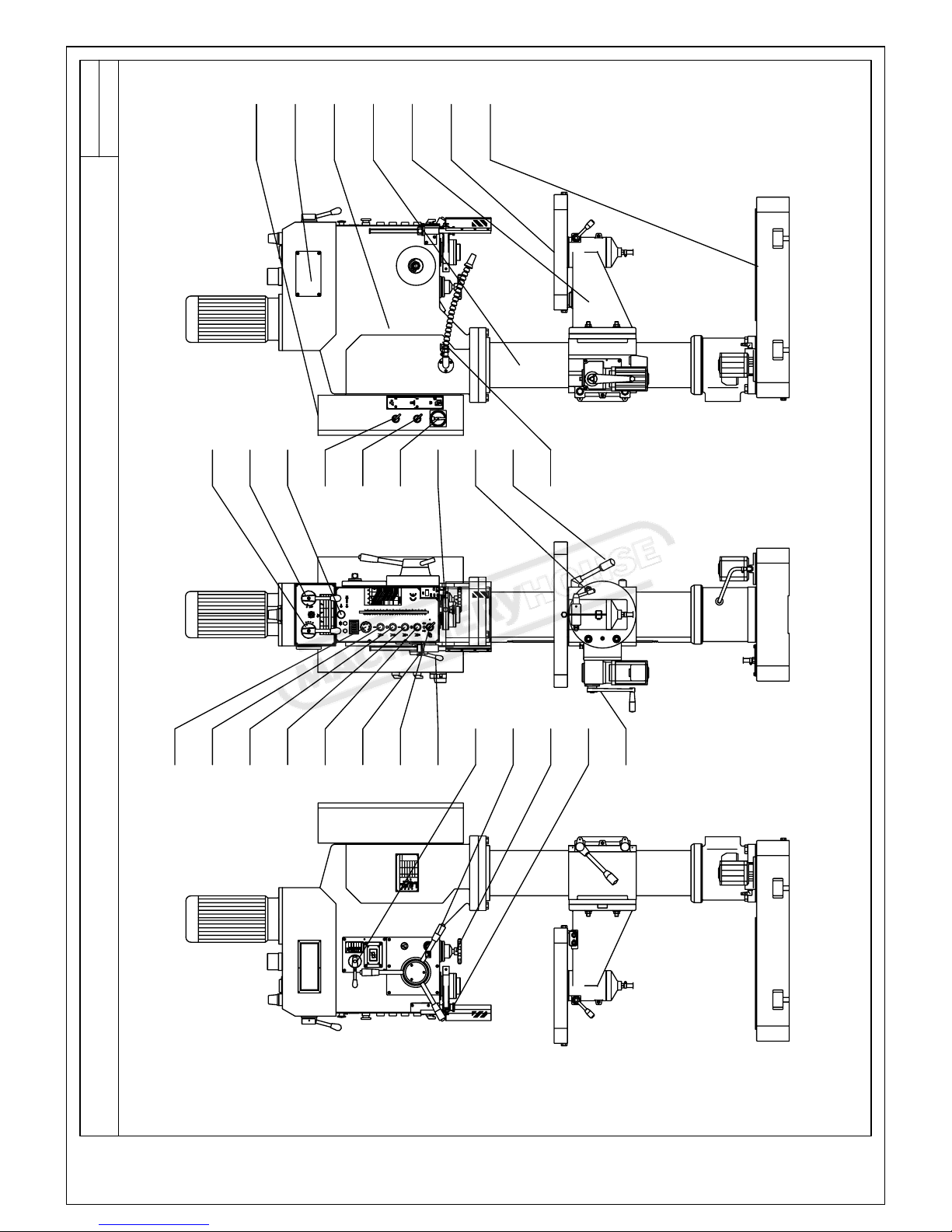
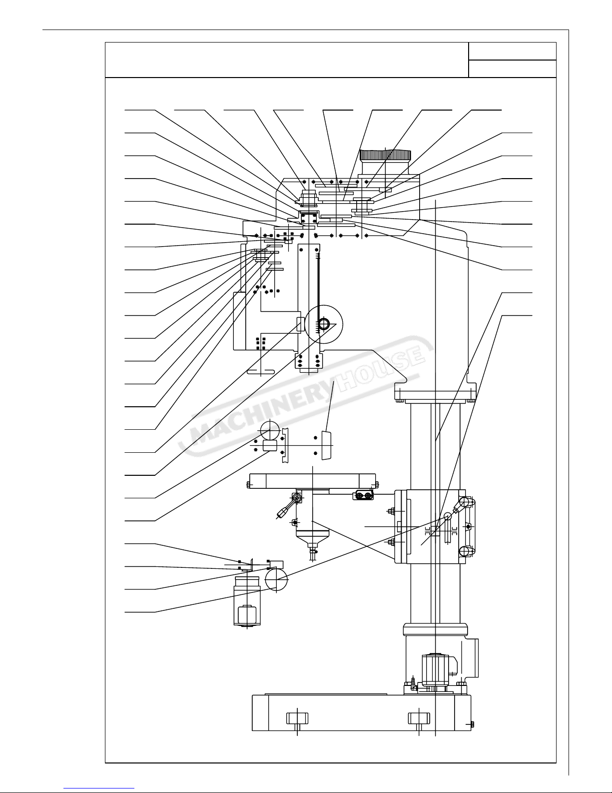
1.10 Superior quality material with special treatment for the wear-resisting purpose has been
used for transmission parts such as gears, worm and worm shaft, rack, lead screw etc as
well as for some key parts like spindle and spindle quill.
1.11 An adjustable safety protection clutch in the spindle feed device is available in order to
prevent the machine and tools from damage when overloaded.
1.12 A safety protection guard under the spindle box is
available as it is not only prevent
coolant splash while cutting but also could observe the machining status.
The guard is interlocked with the spindle, so when the guard is opened, the spindle
could not be running until the protection guard keeps his position.
2. Main technical data:
2.1 Main technical data
No. Name of the items Unit Data
1 Max. drilling diameter (steel) mm 50
2 Max. tapping diameter (steel) mm M30
3 Max. milling cutter diameter mm 80
4 Distance between spindle center line to the center line of column mm 360
5 Max. distance between spindle end to the surface of the worktable
(automatic) mm 585(550)
6 Max. distance between spindle end to the worktable surface of the base mm 1170
7 Max. stroke of the spindle mm 240
8 Spindle taper Morse MT4
9 Number of speed steps of the spindle Step 12
10 Spindle speed range r/min 52~1400
11 Feed steps of the spindle Step 4
12 Feed range of the spindle mm/r 0.1-0.4
13 Max. stroke of worktable and its bracket Mm 530(410)
14 Rotation degree of worktable and its bracket in cross direction degree ±45°
15 Working area of the worktable (Lx W) mm 580×460
16 Working area of the worktable of the base (L x W) mm 445×435
17 Numbers and width of the T sl
ots both for worktable and
worktable of base mm 3-T14, 2-T14
18 Diameter of column mm φ180
20 Power and speed of the main motor Kw, rpm 3/1440
21 Power and speed of the worktable up and down motor. Kw, rpm 0.25/1440
22 Power and flow rate of the coolant pump motor Kw, L/min 0.085/6
23 Machine dimension (L x W x H) mm 950×680×2405
24 Weight of the machine (Net weight/Gross weight) Kg 670/730
Page 5
Instruction Manual for GHD-50 (D178)
23/12/2014

Operation Manual Total 26
page 4
2.2 For the machine appearance and its main technical data, see diagram 1.
3. Brief description of the driving system and its structure:
The machine consists of spindle box, column, machine base, worktable and its bracket,
electric cabinet, coolant device and machine accessories, total seven component parts.
Spindle revolution is main motion of the machine. During drilling and milling processing,
spindle movement along with its axis is a feed motion, during milling operation, movement
of worktable in longitudinal or cross directions or rotation of the worktable is also a feed
motion. Worktable up and down movement and worktable turn round itself is an auxiliary
motion. To those big or higher work piece that could be clamped on the worktable of the
base. The worktable and its bracket should turn round the column to a proper area far away
from the machining area.
Two separately vertical motors realize machine transmission.
A special pump supplies
coolant water.
Two operating levers in the front of spindle box could make changes for the spindle speed
in 12 steps.Changing either lever position could drive a triple gear and a quadruple gear
moving along
with axis direction results the speed change. One of levers has an idle
position that is for the spindle rotation by manual for loading and unloading of tool cutters
as well as for the adjustment of work piece only. Adjustment of the feed rate could be
realized by shifting a set of gears controlled by changing a lever position in the right corner
of spindle box. It also has an idle position for disengaging power feed transmission of the
spindle for the micro adjustment of the spindle by manual.
Up and down movement of the worktable and its bracket is completed by a vertical speed
reduction motor. Of cause, little adjustment for the height of the worktable could also be
made by manual.
Two kinds of lubrication, auto or manual, of the machine are available. Auto lubrication
system consists of a filter ( located inside of a tank under spindle box), a lubrication oil
pump and an oil distributor (located on the top of spindle box), a visual window and an oil
nozzle etc.
Please refer to the diagram 2 for the transmission system of the machine.
For the gear, worm and worm shaft, rack and pinion etc, please see table 1.
For the details of roller bears to be used on the machine, please refer to the diagram 3 and for
a list of roller bears, please refer to the table 2.
Page 6
Instruction Manual for GHD-50 (D178)
23/12/2014

Operation Manual Total 26
drawing(1)picture of appearance of machine
Page 5
column
base
bracket seat
worktable
spindle box
electric box
speed-change box
1
2
4
3
5
6
7
8
9
10
11
12 14
15
16
17
18
19
20
21
22
23
1"
20
10
0"
0
mm/in
OFF
ON/O
6.25
0.2
150
130
140
120
100
110
90
70
60
50
40
30
80
2"
3"
150
86
6"
5"
4"
mild steel
cast iron
6.94
6.21
0.3
0.2
10.42
8.33
9.25
9.38
10.40
11.57
0.2
0.3
0.2
0.3
8.09
0.3
30
35
40
45
50
240
230
220
190
200
170
180
210
160
/min
n
400
695
515
215
300
8"
7"
FKN
1.67
3.33
2.67
1.20
5.21
3.34
4.17
mm/
s
0.2
0.2
0.2
0.2
0.3
0.2
0.1
0.2
0.2
mm
D
10
20
15
25
5.78
0.3
The cutting rating chart
for reference
9"
330
1050
95
TOOL SETTING
TOOL DISMOUNTING
790
250
0
580
180
72 52
xmin
OFF
13
0.30
0.40
0.20
0.10
0
mm/r
4
3
2
1
Chart of lubrication position
lubrication period
Oiling once for each
shift
Oiling once for each
shift
Changing grease
once every 6 month
Oiling once for each
shift
Oiling once for each
shift
Oiling once for each
shift
6
5
64
Worm bearing for
Carriage lifting
Surface of upright
column
Carriage lifting
device
No.of
lubrication
position
5
3
2
1Oil pool of
spindleboox
Surface of main
spindle sleeve
Surface of upright
column
lubrication
position
No.40
lubricant
Grease
designation
Page 7
Instruction Manual for GHD-50 (D178)
23/12/2014

Operation Manual Total 26
drawing 2 picture of transmission
page 6
10
9
6
7
8
23
22
21
20
19
18
17
16
15
14
13
12
11
24 25 26 2827 29 30
33
37
36
35
34
32
31
1
2
3
4
5
38
39
Page 8
Instruction Manual for GHD-50 (D178)
23/12/2014

Operation Manual Total 26
page 7
4.1 list of gear, worm wheel,worm and rack table
(
1
)
Number on
the drawing 1 2 3 4 5 6 7 8 9 10
Part drawing
NO. 12017 12012 12013 12011 32080 32036 31009 32064 32041 32042
N
umber of
teeth and
starts
40 1 26 30 15 37 70 1 36 26
Module 2 2 1.5 1.5 2.5 2.5 2 2 1.75 1.75
D
irection of
helical angle
Class of
Accuracy 9 9 9 9 8-7-7 8 8 9 8-7-7 8-7-7
Material 45 45 45 45 45 QT400 45 45 45
Heat
treatment and
hardness
T235 T235 T235 T235 HV500 T235 G48 G48
Number on
the drawing 11 12 13 14 15 16 17 18 19 20
Part drawing
NO. 32043 32059 32058 32044 32057 32056 32045 32046 32052 32048
Number of teeth
and starts
17 22 32 32 41 26 43 15 60 25
Module 1.75 1.75 1.75 1.75 1.75 1.75 1.75 1.75 1.75 1.75
D
irection of
helical angle
Class of
Accuracy 8-7-7 8-7-7 8-7-7 8-7-7 8-7-7 8-7-7 8-7-7 8-7-7 8-7-7 8-7-7
Material 45 45 45 45 45 45 45 45 45 45
Heat
treatment and
hardness G48 G48 G48 G48 G48 G48 G48 G48 G52 G52
Page 9
Instruction Manual for GHD-50 (D178)
23/12/2014

Operation Manual Total 26
page 8
4.1 list of gear, worm wheel,worm and rack table
(
1
)
Number on
the drawing 21 22 23 24 25 26 27 28 29 30
Part drawing
NO. 32049 32049 32009 32009 32010 32013 32014 32023 32016 32017
N
umber of
teeth and
starts
62 40 40 40 18 61 50 40 64 22
Module 2.5 1.5 1.5 2 2.5 2.5 2.5 2.5 2 2
D
irection of
helical angle
Class of
Accuracy 7-6-6 9 9 7-6-6 7-6-6 7-6-6 7-6-6 7-6-6 7-6-6 7-6-6
Material 40Cr 40Cr 40Cr 40Cr 40Cr 40Cr 40Cr 40Cr 40Cr 40Cr
Heat
treatment and
hardness
G42 G42 G42 G52 G52 G52 G52 G52 G52 G52
Number on
the drawing 31 32 33 34 35 36 37 38 39
Part drawing
NO. 32018 32019 32020 32022 32025 32026 32027 12004 12015
Number of teeth
and starts
25 35 30 20 45 18 55 77 14
Module 2.5 2.5 2.5 2.5 2.5 2.5 2.5 2.5 2.5
D
irection of
helical angle
Class of
Accuracy 7-6-6 7-6-6 7-6-6 7-6-6 7-6-6 7-6-6 7-6-6 9 9
Material 40Cr 40Cr 40Cr 40Cr 40Cr 40Cr 40Cr 45 45
Heat
treatment and
hardness
G52 G52 G52 G52 G52 G52 G52 T235 T235
Page 10
Instruction Manual for GHD-50 (D178)
23/12/2014

Operation Manual Total 26
drawing 3 picture of rolling bearing
page 9
16
2
18
12
5
14
11
14
15
6
13
10
8
4
3
1
4
17
9
7
7
Page 11
Instruction Manual for GHD-50 (D178)
23/12/2014

Operation Manual Total 26
page 10
Roller bearing table
Table (2)
No. Model Name Specification Q’ty
Accuracy
1 GB276,102 Deep racing ball bearing 12×35×8 1
2 GB276,104 Deep racing ball bearing 20×42×12 1
3 GB276,106 Deep racing ball bearing 30×55×13 1
4 GB276,202 Deep racing ball bearing 15×35×11 2
5 GB276,204 Deep racing ball bearing 20×47×14 2
6 GB276,303 Deep racing ball bearing 17×47×14 1
7 GB276,1000909 Deep racing ball bearing 45×68×12 2
8 GB276,D1000909 Deep racing ball bearing 45×68×12 1 D
9 GB276,7000102 Deep racing ball bearing 15×32×8 1
10 GB276,7000103 Deep racing ball bearing 17×35×8 2
11 GB276;7000106 Deep racing ball bearing 30×55×9 2
12 GB276;D7000110 Deep racing ball bearing 50×80×10 2 D
13 GB277,50202
Deep racing ball bearing with
stop moving racing outside 15×35×11 1
14 GB277;50204 Deep r
acing ball bearing with
stop moving racing outside 20×47×14 3
15 GB297;2007107E Roller bearing 35×62×18 1
16 GB301,8102 Thrust bearing 15×28×9 2
17 GB301,8104 Thrust bearing 20×35×10 1
18 GB301,8110 Thrust bearing 50×70×14 1
Page 12
Instruction Manual for GHD-50 (D178)
23/12/2014

Operation Manual Total 26
page 11
4. Electrical system
4.1 Brief description
The machine with foreign advanced singlechip and superior quality electric element is controlled by electric
system, the software system not only
realize all kinds movement control ,but also has many protective
function with catenation, the capability of this system is very good ,and the movement of this system is
jarless and reliable.the move and stop of the main motor function are used by electric circuitry, and it
improved the arrury of machine’s drilling.
4.2 Explanation of the circuit
When using the machine,breaker QF1,QF2,QF3 which positioned electric box B1( drawing 4) must be
closed,it can be opened when examined and repaired. The two breakers separately protect short circuit、over
loading and short phase of spindle motor and pump motor .when close the chief switch QS1, the system is
entering working state and the single lamp HL1 ligh up ,when break the chief electric source, the lamp
crush out and working stopped.
4.3 Tapping operation:
Electric Element for the tapping control mainly contactors KM1 and KM2, selection switch SX1 and limit
switches SQ2 and SQ3 for tapping depth control.put the selection switch SX1 into the “1”(“0”is for hole
drilling only),arrange the spindle revolution in clockwise direction KM1 engaged), put the spindle manual
opration lever in down position until touches work piece, tapping job noe is starting. When requied depth is
reached , the limit switch SQ3 works,
the spindle immediately runs in counter clockwise direction (KM2
engaged), the tap returns out of the work piece, when spindle returns to the up highest position ,the limit
switch SQ2 works, spindle runs in clockwise direction, now one tapping job is finished. If tapping stop is
required, push the button (SB4) on the lever end , the spindle motor will immediately run in count
clockwise direction, that’s all.
If the selection switch SX1 is in the “0”position, normal drilling work starts.
Attention: As the
spindle motor works frequently during tapping,the motor will be hot quickly ,so the
tapping job could not be down for a long time, eight times of tapping per minutes maximum
is recommended as the motor needs cool when it is hot otherwise it will be burned.
4.4Auto feed operation:
When auto feed , moving spindle down 5-6mm, press a push button at the end of either one of the three
levers, now feed clutch is engaged and indicator HL2 on the panel is lighted auto feed job is started.
When required drilling d
epth is reached ,the limited switch will be pressed, then spindle returns
automatically. Press the push button of the lever once angin, auto feed will be stopped and the spindle will
return back to the original place.
Page 13
Instruction Manual for GHD-50 (D178)
23/12/2014

Operation Manual Total 26
drawing(4) picture of electrical element of machine
Page 12
button of hand lever SB4
lamp EL1(SB2)
limit switch SQ3
limit switch SQ1
limit switch SQ2
digital lable
operation panel
operation panel
SB6
SB5
SB3
SB2
SB1
pump motor M3
limit switch SQ4
limit switch SQ6
SX3
wiring box B2
pump motor M2
limit switch SQ5
OFF
electric box B1
button of hand lever SB4
motor of spindle M1
instruction switch(QS1)
switch of coolant pump X2
selection switch of tapping
SX1
Page 14
Instruction Manual for GHD-50 (D178)
23/12/2014

Operation Manual Total 26
page 13
4.5 Emergency stop operation:
If emergency stop is necessary during operation, press emergency push button SB1 that makes
the loss of electric power of the contactor KM1,so the machine is completely stopped .After
eliminating the breakdown ,release the lock of the push button then restart the machine.
4.6 Coolant pump
Revolving the switch of coolant pump right, then the coolant pump is moving and working
with the spindle. When the spindle stopped, the coolant pump stopped too.
4.7 Lifting motor
The clamping handle 22 must be opened when the worktable lifting, turn the push button SX3
at required position.
4.8 Installation of the main motor:
Insert the key of the main motor into the solt position of the spline shaft then fixed by 4-M10
×35 hex screw bolts. Connect three phases and one ground wires to the power supply as per
the electrical Diagram(5) of the machine.(please note the direction of main revolving).
4.9 Sheet metal guard:
The sheet metal guard of this machine has a safety protection function, when it is opened
The spindle can’
t working, until it is closed when the spindle is working now, it immediately
stopped if The sheet metal guard is opened .
4.10 Maintenance of the electric equipment:
Turn off the electric power befere maintenance of the electric equipment starts.The electric
equipment must keep on clean condition. Therefore, regularly cleaning is necessary.
However .liquid such as kerosene, gasoline and detergent etc.is not be allowed for the
cleaning. Wave of power supply shall not be over ±
10% requied by the electric motor.
Maintenance of electric equipment is absolutely important inorder to keep machine works
well.
Page 15
Instruction Manual for GHD-50 (D178)
23/12/2014

1.5mm
2
illumination
24V
EL1
HL1
drawing(5-1) picture of electric element
9V8 W8U8W6U6 V6W3V3U3Y1
M
S
3
M1
3kW
M
S
3
0.25kW
M
S
3
M2
0.18kW
M3
0.75mm
KM3
equipment dividing line
KM1
2
KM2
U2 V2 W2
KM4
1.5mm
2
KM5
V7V5U5 W5 U7
1
(3A)FU3
W7
T1
advise 20A
total power
supply
3φ AC420V 50Hz
pump motor
QS1
V1
W1
U1
PE
QF1
L2
L3
L1
QF2
splind motor
QF3
lifting motor
Operation Manual
84 851412 13
blue
picture of connecting wiring of speed
8
yellow
14
yellow
brown
RVP1
S1
black
KM5
4
KM4
82
11 QL1
SB1
83
W20
0.3A
27V
52 3 4
27V
(5A)FU4
(1A)FU5
U20
8186 7
(1A)FU6
9V
(10A)FU7
18V
SX3-2
33
KM5
35
SX3-1
37
KM4
39
SQ6SQ5
32
31
SQ4
36
1.5mm
2
FU2(3A)
(3A)FU1
control
power supply
12
lifting for table
Total 26
page 14
Attention: The diameter of the line without indicating is 0.75mm .
2
bluebrown black
KM6 KM6
85 84
2
1.5mm
1.5mm
2
total switch
brake
Page 16
Instruction Manual for GHD-50 (D178)
23/12/2014

Operation Manual Total 26
Page 15
drawing(5-2)picture of electric element of machine
clutch
AC27V
KM1
KM2
74
L
13
69
Q1
KM6
70
6
I1+24VN
15
71
6
rotate in clockwise
SB2
FU21(1A)
16
24
COM
4
N1 Q2
66
YC1
YC
brake
I7
reverse rotate
reverse rotate
KM6
I4I3I2
SX1
18
17 SB3
switch
SQ1
SQ4
22
stop
73
start/stop for feed
out/in for tapping
tapping
SB4
19
V1
R1 HL2
FU22(3A)
72
U1
L1
12
I6I5
SQ3
limit position(above) for feed
SQ2
20
limit position (below) for feed
21
SB5
25
Q3
61
SB6
72
KM1
62
KM2
65
Q4
63
KM2
KM1
64
rotate in clockwise
jog
I8
WJ1-8/5F picture of connecting wire
emergency stop
SB1
23
67
Q5
SX2
68
KM3
coolant pump
Attention: The diameter of the line without indicating is 0.75mm .
2
black
brown
blue
black
blue
brown
Page 17
Instruction Manual for GHD-50 (D178)
23/12/2014

Operation Manual Total 26
page 16
Electric components list: Table (3)
Code of
elements
Name Specification Q’ty Remark
QF1 Breaker DZ108-6.3/10A 1
QF2 Breaker DZ108-0.4/0.63A 1
QF3 Breaker DZ47-63(D) 3P 3A 1
QS1 Instruction switch JCH13-20 1
SX1,2 Selection switch C2SS2-10B-10 2
SB1 Emergency stop button
MPMT3-10R 1
MCBH-00 1
MCB-01 2
SB2,5 Push button CP1-10G-10 2
SB6 Push button CP1-10B-10 1
SB3 Push button CP1-10R-01 1
SB4 Push button Homedade 1
SX3 Selection push button C3SS2-10B-20 1
SQ1,SQ5,SQ6 Micro switch E62-10A 3
SQ2,SQ3 Adjacent switch TL-Q5MC1 2
SQ4 Micro switch SND4112-SP-C1 1
KM1–KM2 Contactor AS12-30-01-20(AC24V),CA3-01 Each 2
KM3 Contactor HH54P ,AC24V(match seat) 1
KM4-KM6 Contactor AS12-30-01-20(AC24V) 3
HL1,HL2 Single lamp AD17-16 AC24V 2
EL1 Illuminating light AC24 V,25W 1
T1 Transformer JBK5-250TH, 420/24,27,27,9,18 1
R1 Resistor RT 2W62Ω1
V1 Diode IN5404 1
U1 Control panel WJ1-8/5F 1
QL1 Bridge wiring QL 10A 200V 1
RVP1 Tachometer RSD-22 1
Page 18
Instruction Manual for GHD-50 (D178)
23/12/2014

Operation Manual Total 26
page 17
5.Lubrication and coolant system:
Lubrication system:
Parts and bearings inside of the spindle box are all automatically lubricated. Oil level shall
be a little bit higher than the centerline of the oil window when you fill lubrication oil. Too
much oil filling will cause overflowing. Oil release plug and a filter device are in the same
unit located at left side down of the spindle box. Please pay attention that when fastening
your oil release plug, don’
t forget to put the oil absorption pipe inside of the filter,
otherwise no filtered oil will be available. The filter needs to be washed once every two
weeks.
For lubrication places and its requirements by manual. Please refer to the diagram 6.
Coolant system:
A special pump will supply coolant both for tool cutter and for work piece during machining.
Coolant liquid is stored in a compartment located at the backside of the machine base. Flow
rate of the coolant could be adjusted by a ball valve. Regularly washing for the coolant
system is necessary and coolant water shall be exchanged as per actual condition.
6. Hoisting and installation:
Hoisting:
The machine is strongly fixed inside of the crate. When hoisting the machine, please pay
close attention to the sign outside of the crate (where the wire cable shall be placed and
where the gravity center is).
The crate must not be reversed or inclined and must not be strongly stroked when lift up the
machine.
Considering small size of the bottom and higher size of the height of the machine package,
therefore, moving the machine by roller is forbidden. Lifting by a crane or by forklift is
recommended.
Please refer to the diagram 7 for the machine lifting. A soft pad between machine and wire
cable is necessary in order to avoid paint damage of the machine. Lifting must be slow at
beginning to see if the gravity center is correct.
Page 19
Instruction Manual for GHD-50 (D178)
23/12/2014

Operation Manual Total 26
drawing 6 picture of lubrication
page 18
1
2
4
3
6
5
1"
20
10
0"
0
mm/in
OFF
ON/O
6.25
0.2
150
130
140
120
100
110
90
70
60
50
40
30
80
2"
3"
150
86
6"
5"
4"
mild steel
cast iron
6.94
6.21
0.3
0.2
10.42
8.33
9.25
9.38
10.40
11.57
0.2
0.3
0.2
0.3
8.09
0.3
30
35
40
45
50
240
230
220
190
200
170
180
210
160
/min
n
400
695
515
215
300
8"
7"
FKN
1.67
3.33
2.67
1.20
5.21
3.34
4.17
mm/
s
0.2
0.2
0.2
0.2
0.3
0.2
0.1
0.2
0.2
mm
D
10
20
15
25
5.78
0.3
The cutting rating chart
for reference
9"
330
1050
95
TOOL SETTING
TOOL DISMOUNTING
790
250
0
580
180
72 52
xmin
Page 20
Instruction Manual for GHD-50 (D178)
23/12/2014
Table of contents
Other Hafco Drill manuals
Popular Drill manuals by other brands

LITTLE BEAVER
LITTLE BEAVER Hydraulic Earth Drill Operator's manual

Worx Professional
Worx Professional WU171 manual

Power Craft
Power Craft 4500 instruction manual

Black & Decker
Black & Decker EPC126 user manual

Hausmann
Hausmann J0Z-SP16-1315 Operator's manual

Stanley
Stanley FatMax FME140 instruction manual

Matco Tools
Matco Tools MCL2012DDA operating instructions

Ingersoll-Rand
Ingersoll-Rand 5 series Operation and maintenance manual

Makita
Makita M6500 instruction manual

Makita
Makita 6270D instruction manual

Panasonic
Panasonic EY7411 - CORDLESS DRILL & DRIVER operating instructions

Ozito
Ozito OZCD18V2A Operation manual