hager TYB692C User manual

1
Window interface / fl ush-mounted
Fensterschnittstelle / Up
z
e
TYB692C
6LE000839A 82573407
6LE000839A
Device components
picture1: Window interface
(1) Control cable
(2) Programming button and LED
(3) Connection of mains and power cables
Safety instructions
• Electrical equipment may only be installed and
fi tted by qualifi ed electricians.
• Failure to observe the instructions may cause
damage to the device and result in fi re and
other hazards.
• The device is not suitable for disconnection
from supply voltage.
• The connected actuators are not electrically
isolated from the mains - even when switched
off.
• Do not connect any external voltage to the
inputs, since doing so may damage the device
(s), and the SELV potential on the KNX bus line
will no longer be available.
• For parallel connection of several drives
to an output it is indispensable to observe
the corresponding instructions of the
manufacturers, and to use a cutoff relay
if necessary. There is otherwise risk of
irreparable damage to the drives.
• Use only Venetian blind drives with mechanical
or electronic limit switches. Check the limit
switches for correct adjustment. Observe the
specifi cations of the motor manufacturers.
• These instructions are an integral part of
the product, and must remain with the end
customer.
Product characteristics
- Control of Venetian blinds, awnings and similar
blinds
- Control of electrothermal actuators
- Three binary inputs for potential-free contacts,
usable as extension inputs for local operation
- Supply via bus, no additional power supply
necessary
Venetian blind function
- Blind position directly controllable
- Slat position directly controllable
- Feedback of movement status, blind position and
slat position
- Forced position through higher-level controller
- Safety function: 3 independent wind alarms, rain
alarm, frost alarm
- Sun protection function
Actuator function
- Switching operation or PWM operation
- Actuators with characteristics opened or closed
without power
- Overload-protected, short circuit-protected
- Protection against jamming valves
- Forced position
- Cyclical monitoring of the input signals
confi gurable.
€
i
PWM operation: electrothermal actuators only
have the positions Open and Closed. In PWM
operation, switch-on and switch-off during the
drive's cycle time achieves an almost constant
behaviour.
Information for qualifi ed electricians
Fitting and electrical connection
qDANGER!
Electrical shock when live parts are
touched.
Electrical shocks can be fatal.
Before working on the device,
disconnect the power supply and
cover up live parts in the working
environment.
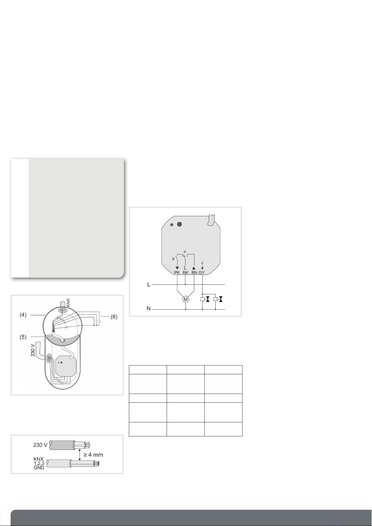
Connection assignment, power cables
BK, black: connection L
BN, brown: connection of Venetian blind, up
PK, pink: connection of Venetian blind, down
GY, grey: actuator connection
Connection assignment of control cable
picture 2: Window interface
RD, red: KNX+
BK, black: KNX–
GN, green: input 1
YE, yellow: input 2
WH, white: input 3
BN, brown: COM inputs 1...3
Function
System information
This device is a product of the KNX system and
complies with the KNX directives. Detailed technical
knowledge obtained in KNX training courses is a
prerequisite to proper understanding.
The function of this device depends upon the
software. Detailed information on loadable software
and attainable functionality as well as the software
itself can be obtained from the manufacturer´s
product database.
Planning, installation and commissioning of the
device are carried out with the aid of KNX-certifi ed
software. Full functionality with KNX commissioning
software version ETS3.0d onwards.
An updated version of the product database,
technical descriptions and conversion programs
and other auxiliary programs are available on our
Internet website.
Intended purpose
Window interface (picture 1):
- Switching of electrically-driven Venetian blinds,
awnings and similar blinds for AC 230 V mains
voltage.
- Switching of electrothermal actuators
- Installation in appliance box to DIN 49073
- Connection with enclosed terminals
Bn,.:
V2.7.0
V2.7.0

2
Connecting and mounting the device
qDANGER!
When connecting the bus/
extensions and mains' voltage wires
in a shared appliance box, the KNX
bus cable may come into contact
with the mains voltage.
The endangers the safety of the
entire KNX installation. People at
remote devices may also receive an
electric shock.
Do not place bus/extensions and
mains voltage terminals in a shared
connection compartment. Use an
appliance box with a fi xed partition
wall (picture 3) or separate boxes.
picture 3
(4) Appliance box
(5) Partition
(6) Potential-free contacts, e.g. for window contact
or installation pushbuttons
picture 4
Minimum spacing between the mains voltage and
bus/extension wires: 4 mm (picture 4).
• Connect the load (picture 5). Use the supplied
sprung screwless terminals. Flexible cable ends
must be tin-plated.
• Connect the device to KNX.
• If necessary, connect potential-free contacts (6)
to inputs (picture 2).
• Install the device in the appliance box.
picture 5
€
i
In the as-delivered state, Inputs 1 and 2 operate
the Venetian blind output. Input 3 has no function.
Function of Inputs 1 and 2 in the as-delivered
state
Input NO contact Blind
1 Press briefl y Adjust slats
Up / Stop
1Press for a
long time
Move up
2Press briefl y Adjust slats
Down / Stop
2Press for a
long time
Move down
Commissioning
Load the address and the application software
• Switch on the bus voltage
• Assign physical addresses and load application
software into the device.
• Note the physical address on the device label.
Appendix
Technical data
Window interface 1gang fl ush-mounted
Supply
Rated voltage ................................. 230 / 240 V ~
Mains frequency .................................. 50 / 60 Hz
Switching voltage ..................................... 250 V~
Ambient conditions
Ambient temperature ........................ -5 ... +45 °C
Storage/transport temperature ........ -25 ... +70 °C
Venetian blind output
Contact type .......................................................μ
Switching current AC1 .................................... 3 A
Minimum switching current AC ................ 100 mA
Motors 230 V ............................................ 600 VA
Motors 110 V .................................................... —
Heating output
Output type ..................Semi-conductor (Triac), ε
Switching current ............................... 5 ... 25 mA
Switch-on current ....................max. 600 mA (2 s)
Number of drives per output .....................max. 2
Control cable and inputs
Control cable (preterminated) ................. YY6x0.6
Input type ....................................... Potential-free
Total length of extension
unit cable ................................................max. 5 m
Poll voltage, extension inputs ........... approx. 5 V
Dimension Ø×H ................................. 53×28 mm
Connection type ..................Terminal (enclosed)
Single-stranded .......................... 1.0 ... 2.5 mm²
KNX medium ............................................... TP 1
Commissioning mode ............................. S mode
Rated voltage KNX ............DC 21 V ... 32 V SELV
Power consumption KNX .............. max. 240 mW
Own consumption on the KNX Bus:
- typical ................................................ 11,5 mA
- standby ............................................... 6,7 mA
6LE000839A

6LE000839A
3
Window interface / fl ush-mounted
Fensterschnittstelle / Up
z
e
TYB692C
6LE000839A 82573407
Geräteaufbau
Bild 1: Fensterschnittstelle
(1) Steuerleitung
(2) Programmiertaste und -LED
(3) Anschluss Netz- und Lastleitungen
Sicherheitshinweise
• Einbau und Montage elektrischer Geräte
dürfen nur durch Elektrofachkräfte erfolgen.
• Bei Nichtbeachten der Anleitung können
Schäden am Gerät, Brand oder andere
Gefahren entstehen.
• Das Gerät ist nicht zum Freischalten geeignet.
• Angeschlossene Stellantriebe sind - auch im
ausgeschalteten Zustand - nicht galvanisch
vom Netz getrennt.
• An die Eingänge keine externen Spannungen
anschließen, andernfalls kann es zu
Geräteschäden kommen und SELV-Potential
auf der KNX-Busleitung ist nicht mehr
gegeben.
• Sollen mehrere Antriebe an einem Ausgang
parallelgeschaltet werden, unbedingt Angaben
der Hersteller beachten, gegebenenfalls
Trennrelais verwenden. Andernfalls könnten
die Antriebe zerstört werden.
• Nur Jalousieantriebe mit mechanischen oder
elektronischen Endlagenschaltern verwenden.
Endlagenschalter auf korrekte Justierung
prüfen.
Angaben der Motorenhersteller beachten.
• Diese Anleitung ist Bestandteil des Produktes
und muss beim Endkunden verbleiben.
Produkteigenschaften
- Steuerung von Jalousien, Markisen und ähnlichen
Behängen
- Ansteuerung elektrothermischer Stellantriebe
- Drei Binäreingänge für potentialfreie Kontakte,
nutzbar als Nebenstelleneingänge zur Vor-Ort-
Bedienung
- Versorgung über Bus, keine zusätzliche
Versorgungsspannung notwendig
Jalousiefunktion
- Behangposition direkt ansteuerbar
- Lamellenposition direkt ansteuerbar
- Rückmeldung von Fahrzustand, Behangposition
und Lamellenstellung
- Zwangsstellung durch übergeordnete Steuerung
- Sicherheitsfunktion: 3 unabhängige Windalarme,
Regenalarm, Frostalarm
- Sonnenschutzfunktion
Funktion Stellantriebe
- Schaltbetrieb oder PWM-Betrieb
- Stellantriebe mit Charakteristik stromlos geöffnet
oder stromlos geschlossen ansteuerbar
- Überlastsicher, kurzschlusssicher
- Schutz gegen festsitzende Ventile
- Zwangsstellung
- Zyklische Überwachung der Eingangssignale
parametrierbar.
€
i
PWM-Betrieb: Elektrothermische Stellantriebe
besitzen nur die Stellungen Offen und Geschlossen.
Im PWM-Betrieb wird durch Einund Ausschalten
innerhalb der Zykluszeit des Antriebs ein quasi-
stetiges Verhalten erreicht.
Informationen für Elektrofachkräfte
Montage und elektrischer Anschluss
qGEFAHR!
Elektrischer Schlag bei Berühren
spannungsführender Teile.
Elektrischer Schlag kann zum Tod
führen.
Vor Arbeiten am Gerät freischalten
und spannungsführende Teile in der
Umgebung abdecken!
Anschlussbelegung Lastleitungen
BK, schwarz: Anschluss L
BN, braun: Anschluss Jalousieantrieb, Auf
PK, rosa: Anschluss Jalousieantrieb, Ab
GY, grau: Anschluss Stellantrieb
Anschlussbelegung Steuerleitung
Bild 2
RD, rot: KNX+
BK, schwarz: KNX–
GN, grün: Eingang 1
YE, gelb: Eingang 2
WH, weiß: Eingang 3
BN, braun: COM Eingänge 1...3
Funktion
Systeminformation
Dieses Gerät ist ein Produkt des KNX-Systems und
entspricht den KNX-Richtlinien. Detaillierte
Fachkenntnisse durch KNX-Schulungen werden
zum Verständnis vorausgesetzt.
Die Funktion des Gerätes ist softwareabhängig.
Detaillierte Informationen über Softwareversionen
und jeweiligen Funktionsumfang sowie die Software
selbst sind der Produktdatenbank des Herstellers
zu entnehmen.
Planung, Installation und Inbetriebnahme
des Gerätes erfolgen mit Hilfe einer KNX-
zertifi zierten Software. Volle Funktionalität mit
KNXInbetriebnahme-Software ab Version ETS3.0d.
Produktdatenbank, technische Beschreibungen
sowie Konvertierungs- und weitere Hilfsprogramme
fi nden Sie stets aktuell auf unserer Internet-Seite.
Bestimmungsgemäßer Gebrauch
Fensterschnittstelle (Bild 1):
- Schalten elektrisch betriebener Jalousien,
Markisen und ähnlicher Behänge für
Netzspannung AC 230 V.
- Schalten elektrothermischer Stellantriebe
- Montage in Gerätedose nach DIN 49073
- Anschluss mit beiliegenden Verbindungsklemmen
Bn,.:
V2.7.0
V2.7.0

4Hager Controls S.A.S., 33 rue Saint-Nicolas, B.P. 10140, 67703 SAVERNE CEDEX, France - www.hager.com 10/2015 - 6LE000839A
Gerät anschließen und montieren
qGEFAHR!
Bei Anschließen der Bus-/Neben-
stellenund Netzspannungsadern
in einer gemeinsamen Gerätedose
kann die KNX-Busleitung mit
Netzspannung in Berührung
kommen.
Die Sicherheit der gesamten
KNXInstallation wird gefährdet.
Personen können auch an entfernten
Geräten einen elektrischen Schlag
erhalten.
Bus-/Nebenstellen- und Netzspan-
nungsklemmen nicht in einem
gemeinsamen Anschlussraum
plazieren. Gerätedose mit fester
Trennwand (Bild 3) oder separate
Dosen verwenden.
Bild 3
(4) Gerätedose
(5) Trennwand
(6) potentialfreie Kontakte, z. B. für Fensterkontakt
oder Installationstaster
Bild 4
Mindestabstand zwischen Netzspannung und
Bus-/Nebenstellenadern: 4 mm (Bild 4).
• Last anschließen (Bild 5). Beiliegende
Federsteckklemmen verwenden. Flexible
Leiterenden müssen verzinnt sein.
• Gerät an KNX anschließen.
• Ggf. potentialfreie Kontakte (6) an Eingänge
anschließen (Bild 2).
• Gerät in Gerätedose montieren.
Bild 5
€
i
Im Auslieferungszustand bedienen die Eingänge
1 und 2 den Jalousieausgang. Eingang 3 hat
keine Funktion.
Funktion der Eingänge 1 und 2 im
Auslieferungszustand
Eingang Schließer Behang
1 kurz betätigen Lamellen
verstellen
Auf / Stop
1lang betätigen Auffahren
2kurz betätigen Lamellen
verstellen
Ab /Stop
2lang betätigen Abfahren
Inbetriebnahme
Adresse und Anwendungssoftware laden
• Busspannung einschalten.
• Physikalische Adresse vergeben und
Anwendungssoftware in das Gerät laden.
• Physikalische Adresse auf Geräteetikett notieren.
Anhang
Technische Daten
Fensterschnittstelle 1/1fach Up
Versorgung
Nennspannung ......................... AC 230 / 240 V ~
Netzfrequenz ....................................... 50 / 60 Hz
Schaltspannung ................................. AC 250 V~
Umgebungsbedingungen
Umgebungstemperatur .................... -5 ... +45 °C
Lager-/Transporttemperatur ............ -25 ... +70 °C
Jalousieausgang
Kontaktart ...........................................................μ
Schaltstrom AC1 ............................................ 3 A
Mindestschaltstrom AC ........................... 100 mA
Motoren 230 V .......................................... 600 VA
Motoren 110 V ..................................................—
Heizungsausgang
Ausgangsart ............................Halbleiter (Triac), ε
Schaltstrom ........................................ 5 ... 25 mA
Einschaltstrom .........................max. 600 mA (2 s)
Anzahl Antriebe pro Ausgang ....................max. 2
Steuerleitung und Eingänge
Steuerleitung (vorkonfektioniert) ............. YY6x0,6
Eingangsart .......................................potentialfrei
Gesamtlänge Nebenstellenleitung .........max. 5 m
Abfragespannung Nebenstelleneingänge
....ca. 5 V
Abmessung Ø×H ............................... 53×28 mm
Anschlussart ......................Verbindungsklemme
(beiliegend)
eindrähtig ....................................... 1 ... 2,5 mm²
KNX Medium ............................................... TP 1
Inbetriebnahmemodus ............................S-Mode
Nennspannung KNX ..........DC 21 V ... 32 V SELV
Leistungsaufnahme KNX ............... max. 240 mW
Eigenverbrauch am KNX-Bus:
- typisch .................................................. 11,5 mA
- im Ruhezustand .................................... 6,7 mA
Table of contents
Languages:
Other hager Recording Equipment manuals
Popular Recording Equipment manuals by other brands

Roland
Roland V-Bass owner's manual

Rocktron
Rocktron Cyborg Operation manual

Wirepath Surveillance
Wirepath Surveillance WPS-100-NVR-4IP Installation and user manual

Mitsubishi Electric
Mitsubishi Electric PAC-US444CN-1 Installation and instruction manual

IMG STAGE LINE
IMG STAGE LINE DELTA-160R Brief instructions

digi-tech
digi-tech DSP-128 owner's manual