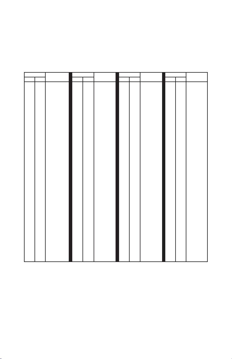
When using the Extended ASCII mode, characters are received which
are in the range of value from 0x00 to 0xFF (0 to 255 decimal). The
corresponding USB keystroke from the table will be generated.
Extended ASCII Mode allows for the ANSI/ISO Latin-1 character group
in the range of 0x80 to 0xFF (128 to 255 decimal) to be produced as
well as the standard 0x00 through 0x7F ASCII codes. Additionally in
this mode, the F1-F10 keys are supported for the character range of
codes 0x11 to 0x1A values respectively. F11 and F12 keys are sent for
received characters of 0x0E and 0x0F in the Extended ASCII mode.
Example 1: If the value 0x41 (decimal 65) is received in this mode, a
capital “A” character will be produced on the target computer at the
USB end of the cable.
Example 2: If the value 0xA9 (decimal 169) is received in this mode,
a “©” character will be produced on the target computer at the USB
end of the cable.
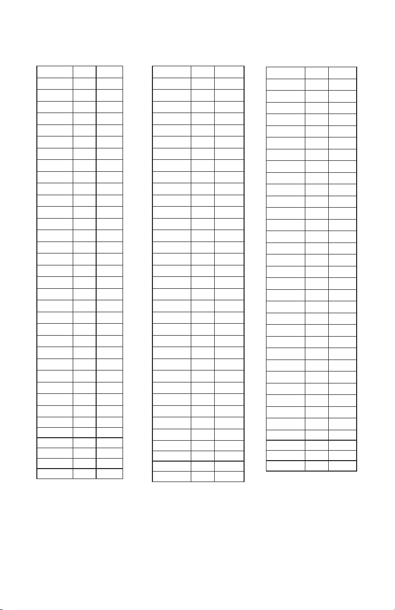
Key Number Mode
The Key Number Mode provides users with complete control of the
generation of the make (activation) and break (deactivation) of any
standard keyboard key. In this mode, a single byte will command
the make or break of a specific keyboard key at the target computer.
Using this mode allows for generation of any keystroke or combination
of keystrokes on the target computer.
In general, to make a key (generate a press of a specific key), a one
byte value between 0x00 and 0x7F is sent to the USB-ASC232. Once
received, the key specified will be seen as held down on the computer
just as if someone was physically holding that key on a keyboard.
Each time a make is sent for a key, a corresponding break (release) of
that key must be done at a later time to deactivate it. The break code
for a key is the same value as the make code plus 0x80 (128 decimal).
The break code releases the key that was activated earlier by a make
code. See the following table for make and break codes.
613
How far the scroll moves on the computer screen depends on the
scroll system settings of the target computer.
0x00, 0x00, 0x00, 0x18
The next example four RS-232 mouse packets are sent to emulate
a double left mouse click on the target computer.
Packet 1 - 0x00, 0x00, 0x00, 0x09 (left mouse button on)
Now delay around 150 msec for the system to see the button
Packet 2 - 0x00, 0x00, 0x00, 0x08 (left mouse button off)
Delay 150 msec again for the system to see the button release
Packet 3 - 0x00, 0x00, 0x00, 0x09 (left mouse button on)
Delay around 150 msec for the system to see the button
Packet 4 - 0x00, 0x00, 0x00, 0x08 (left mouse button off)
Note that cursor movement, scroll wheel movement and button
actions may all be implemented within the same packet. The
examples above focus only on a particular action at a time for
clarity. For instance, a command that sends both X and Y cusor
movement can also send button information and/or scroll wheel
movement.
Sending Serial Control Commands
The CD included with the unit contains source code examples in
various programming languages to help the user get started on
their own Com Port control software. Use these examples as a
starting point for programs which run the communication to the
USB-ASC232 from the computer attached to the USB-ASC232
Com Port DB9 connector.