the outlet grills of the air conditioner are opened, and
the unit goes on working under the condition before the
grille will close automatically.
Notice:
Cannot pull direct the outlet grille by hand. Otherwise, the
grille will run incorrectly. If the grille is not run correctly,
stop for a minute and then start, adjusting by remote
controller.
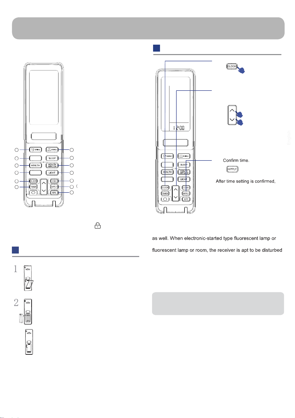
Remote controller can memorize each operation status.
when starting it next time, just press ON/OFF button and
unit will run in previous status.
The setting of
function
The cancel of
function
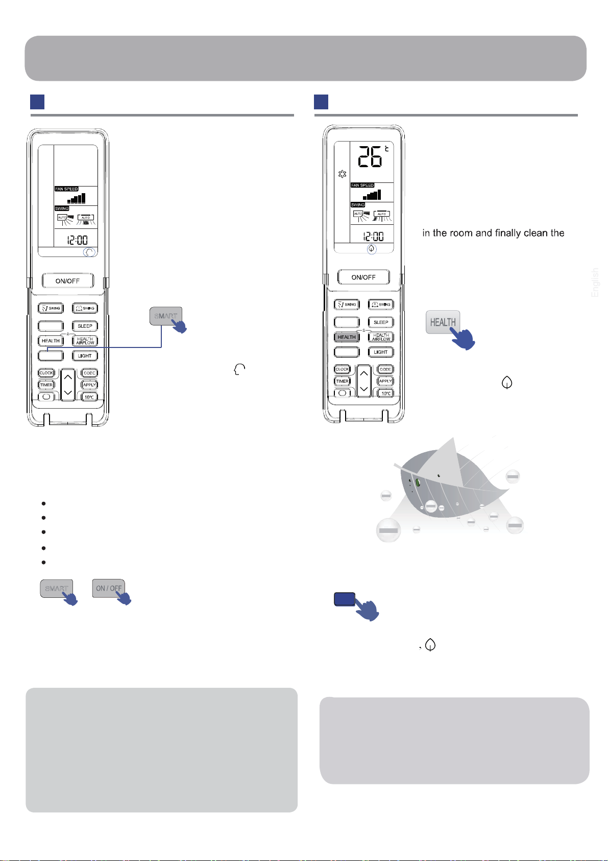
Operation
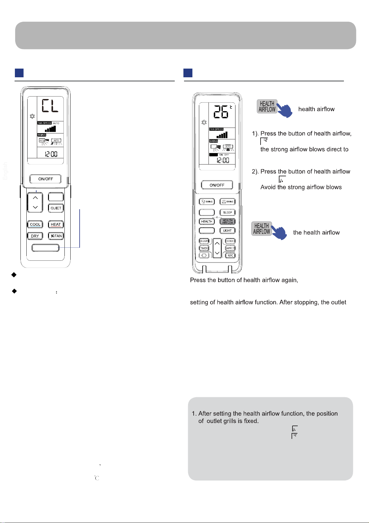
HEALTH AIRFLOW OperationSELF CLEAN Operation
appears on the display. Avoid
the body.
again, appears on the display.
direct to the body.
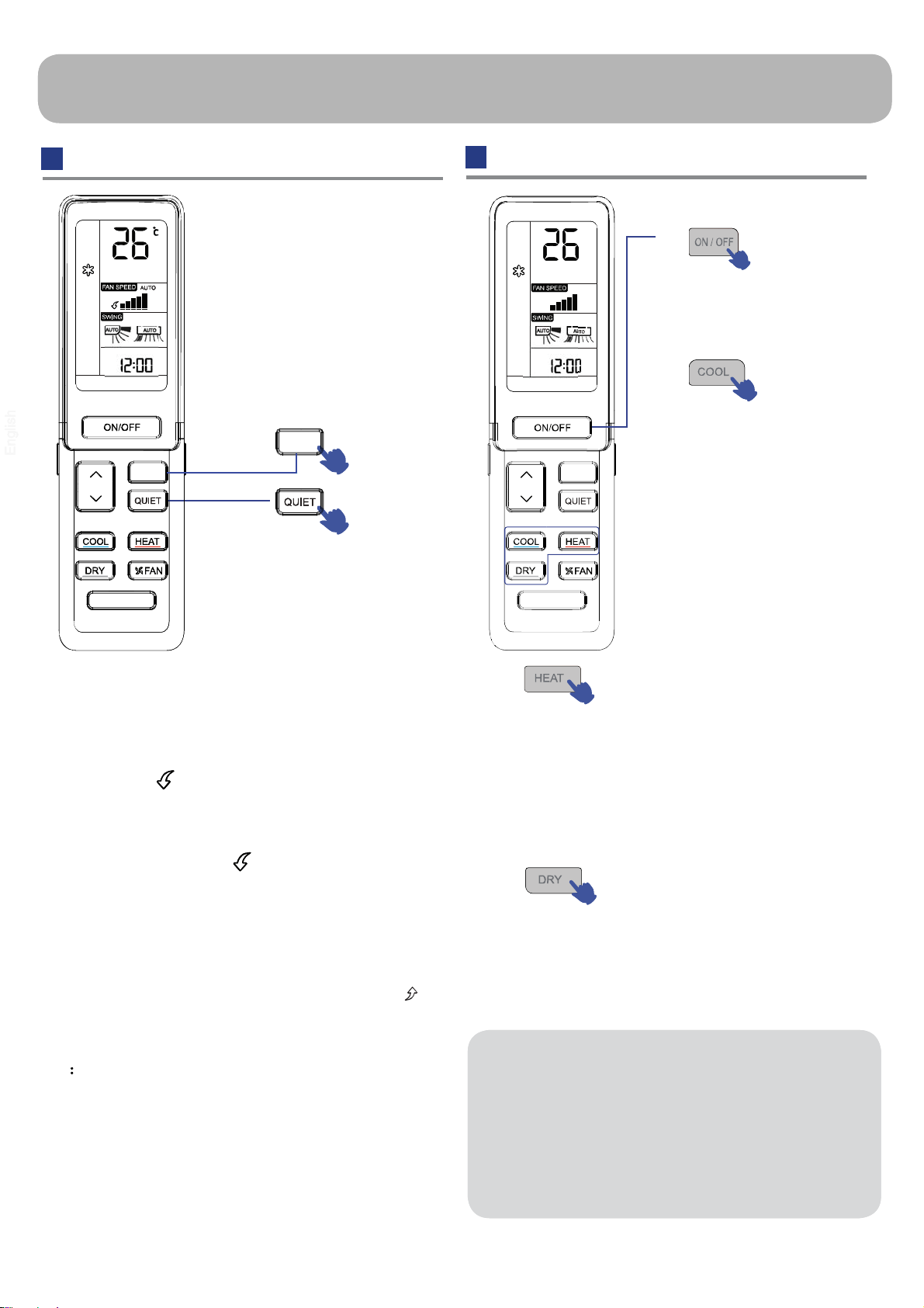
Note:
2. In heating, it is better to select the mode.
3. In cooling, it is better to select the mode.
4. In cooling and dry, using the air conditioner for a
long time under the high air humidity, a phenomenon
falling drips of water occurs at the outlet grille.
5. Select the appropriate fan direction according to the
actual conditions.
TIMER
FAN MODE
SMART
TURBO
SELF CLEAN
SELF CLEAN Operation
Functional description: the purpose of this function is to
clean the evaporator and the condenser.
Entry and exit Press self clean button to enter this
function, then it will display "CL" on the panel of the indoor
unit and also on the remote controller. After running 20-30
minutes, this function will exit automatically with the " Pi "
sound is heard twice, then the unit return to original state.
Under operation process of self clean, press the button
repeatedly has no effect and cannot exit, but the power off
button and other mode button can make it exit.
Note
1.It has no effect under the mode of timer/sleep.
2.After this mode starts, the air volume may reduce or
even have no airflow.
3.It is normal if the unit make some sound like expand with
heat and contract with cold
4. The “CL” display time may last differently on the remote
controller and panel.
5
5. During the self clean process of the outdoor unit, in order to
dry the evaporator, it’s normal the air conditioner would blow
out hot air occasionally.
6. The self clean effect would be affected by the using environ-
ment. If the cleaning effect is not achieved, please restart the
function after the interval of time.
7. When exit the self clean mode the water vapor would
accoured occasionally.
8. If the temperature is below 5 outside, the unit would only
do the indoor self clean.

 User manual")


 User manual")


 User manual")


 null")