CONTENTS INTRODUCTION
1
The Halstead Hero range consists of six different outputs. The outputs
are available from 30,000 to 90,000 BTU/h and spot rated (non
modulating). All versions are wall mounted, fan assisted balanced flue
natural gas boilers incorporating a cast iron heat exchanger.
The HERO range is for use in fully pumped open-vented or sealed water
central heating systems. The appliances are NOT suitable for semi
gravity systems.
The appliance is fitted with an electronic control device to combine and
provide functions for ignition, manually adjustable central heating
temperature control, pump over-run, frost protection and basic diagnostic
information.
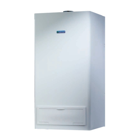
It features an attractive white casing hinged with front door panel. The
hinged front door panel has to be removed if the appliance is to be
fitted within a standard kitchen wall unit.
The appliances are supplied with a standard concentric flue terminal
which is suitable for rear wall thicknesses up to 340mm. For side
horizontal or vertical flueing application the flue kit, part number
955080, is required.
Additional flue kits are available to extend the flue length to any length
as specified in clause 2.
For further information regarding vertical flue terminal installation please
refer to Halstead’s Flue Guide.
Control of substances Hazardous to Health
Under Section 6 of The Health and Safety at Work Act 1974, it is
required to provide information on substances hazardous to health.
Manual Handling Guidance
During the appliance installation it will be necessary to employ caution
and assistance whilst lifting as the appliance exceeds the recommended
weight for a one man lift.
Take care to avoid trip hazards, slippery or wet surfaces.
Insulation material
The insulation material is made of Superwool 612 BB and can cause
irritation to skin, eyes and the respiratory tract.
High dust levels are usually only if the material is broken. Normal
handling shouldn’t cause any discomfort, but it is advised to follow
normal hygiene and wash your hands immediately after working with the
material.
If you do suffer irritations to the eyes or to the skin seek medical
attention.
The adhesives and sealants used in this appliance are cured and give no
hazard in this state.
Note: British standard BS7593: 1992 stresses the
importance of cleansing and flushing of the system to
ensure it continues to run efficiently with the minimum of
maintenance necessary. Halstead Boilers fully support this
professional approach and recommend that the system is
cleansed with an effective chemical cleanser and protected
long term with a suitable inhibitor. Such products are
available from Fernox and Sentinel.
1GENERAL DESCRIPTION
2TECHNICAL SPECIFICATIONS . . . . . . . . . . . . . . .1
2.1 Gas Categories . . . . . . . . . . . . . . . . . . . . . . . . . . . . .1
2.2 Performance data . . . . . . . . . . . . . . . . . . . . . . . . . . . .1
2.3 Connection Sizes . . . . . . . . . . . . . . . . . . . . . . . . . . . . .1
2.4 General specifications . . . . . . . . . . . . . . . . . . . . . . . . .1
2.5 Overall dimensions and minimum clearances . . . . . . . . . .2
2.6 Air/flue duct specification . . . . . . . . . . . . . . . . . . . . . .2
2.7 Se-duct applications . . . . . . . . . . . . . . . . . . . . . . . . . . .4
2.8 Exploded diagram . . . . . . . . . . . . . . . . . . . . . . . . . . . .4
3INSTALLATION REQUIREMENTS . . . . . . . . . . . . . .5
3.1 Statutory requirements . . . . . . . . . . . . . . . . . . . . . . . . .5
3.2 Boiler location . . . . . . . . . . . . . . . . . . . . . . . . . . . . . . .5
3.3 Flue terminal position . . . . . . . . . . . . . . . . . . . . . . . . . .6
3.4 Ventilation requirements . . . . . . . . . . . . . . . . . . . . . . . .6
3.5 Gas supply . . . . . . . . . . . . . . . . . . . . . . . . . . . . . . . . .6
3.6 Data supply . . . . . . . . . . . . . . . . . . . . . . . . . . . . . . . .6
3.7 Electricity supply . . . . . . . . . . . . . . . . . . . . . . . . . . . . .6
3.8 Central heating water systems . . . . . . . . . . . . . . . . . . . .7
3.8.1 Open vented systems . . . . . . . . . . . . . . . . . . . . . . . . . .7
3.8.2 Sealed systems . . . . . . . . . . . . . . . . . . . . . . . . . . . . . .7
4.0 INSTALLING THE APPLIANCE . . . . . . . . . . . . . . . .9
4.1 Unpacking the appliance . . . . . . . . . . . . . . . . . . . . . . .9
4.2 Preparing the wall . . . . . . . . . . . . . . . . . . . . . . . . . . . .9
4.2.1 Rear outlet flue . . . . . . . . . . . . . . . . . . . . . . . . . . . . . .9
4.2.2 Top outlet flue . . . . . . . . . . . . . . . . . . . . . . . . . . . . . .11
4.3 Air/flue duct installation . . . . . . . . . . . . . . . . . . . . . . .11
4.3.1 Preparing the horizontal duct . . . . . . . . . . . . . . . . . . . .12
4.3.2 Installing the horizontal duct from inside the building . . . .13
4.3.3 Installing the horizontal duct from outside the building . . .13
4.3.4 Preparing and installing the vertical duct . . . . . . . . . . . .14
4.4 Gas connection . . . . . . . . . . . . . . . . . . . . . . . . . . . . .14
4.5 Water connections . . . . . . . . . . . . . . . . . . . . . . . . . . .14
4.6 Wiring instructions . . . . . . . . . . . . . . . . . . . . . . . . . . .15
5COMMISSIONING AND TESTING . . . . . . . . . . . .17
5.1 Open vented water systems . . . . . . . . . . . . . . . . . . . . .17
5.2 Sealed water systems . . . . . . . . . . . . . . . . . . . . . . . . .18
5.3 Users instructions . . . . . . . . . . . . . . . . . . . . . . . . . . . .18
5.4 Boiler logbook . . . . . . . . . . . . . . . . . . . . . . . . . . . . .18
6ROUTINE SERVICING INSTRUCTIONS . . . . . . . . .19
6.1 Checking the operation of the appliance . . . . . . . . . . . .19
6.2 Commencing with servicing . . . . . . . . . . . . . . . . . . . . .19
6.3 Fan assembly . . . . . . . . . . . . . . . . . . . . . . . . . . . . . .19
6.4 Main burner assembly & combustion chamber insulation .20
6.5 Ignition and detection electrode insulation . . . . . . . . . . .20
6.6 Injector . . . . . . . . . . . . . . . . . . . . . . . . . . . . . . . . . .20
6.7 Air pressure switch tubes . . . . . . . . . . . . . . . . . . . . . . .20
6.8 Heat exchanger . . . . . . . . . . . . . . . . . . . . . . . . . . . . .20
6.9 Re-assembly . . . . . . . . . . . . . . . . . . . . . . . . . . . . . . .20
6.10 Re-commisioning . . . . . . . . . . . . . . . . . . . . . . . . . . . .20
7REPLACEMENT OF PARTS . . . . . . . . . . . . . . . . .21
7.1 Overheat cut off device . . . . . . . . . . . . . . . . . . . . . . .21
7.2 Flow temperature sensing device . . . . . . . . . . . . . . . . .21
7.3 Air pressure switch . . . . . . . . . . . . . . . . . . . . . . . . . . .21
7.4 Electronic diagnostic and ignition sequence control board 21
7.5 Fan assembly . . . . . . . . . . . . . . . . . . . . . . . . . . . . . .22
7.6 Main burner . . . . . . . . . . . . . . . . . . . . . . . . . . . . . . .22
7.7 Injector . . . . . . . . . . . . . . . . . . . . . . . . . . . . . . . . . .22
7.8 Gas valve . . . . . . . . . . . . . . . . . . . . . . . . . . . . . . . .22
7.9 Igniton / Flame sensing electrode . . . . . . . . . . . . . . . . .22
7.10 Combustion chamber insulation . . . . . . . . . . . . . . . . . .23
7.10.1 Front panel insulation . . . . . . . . . . . . . . . . . . . . . . . . .23
7.10.2 Side panel insulation . . . . . . . . . . . . . . . . . . . . . . . . .23
8INTERNAL WIRING DIAGRAMS . . . . . . . . . . . . .23
9 FAULT FINDING . . . . . . . . . . . . . . . . . . . . . . . .24
10 SHORT PARTS LIST . . . . . . . . . . . . . . . . . . . . . .25

