Hamamatsu ENERGETIQ LDLS EQ-77X User manual

Model EQ-77X
Laser-Driven Light Source LDLS®
Operation Manual
Revision 4
September 2023
DOC-10697

Copyright Information
EQ-77X LDLS® Operation Manual 2of31
Copyright©2023EnergetiqTechnologyInc.Allrightsreserved.
ForalistofpatentsthatcoverEnergetiqproducts,visitwww.energetiq.com/patents.
All technical information, including drawings, schematics, and specifications contained in this manual are the property
of Energetiq and shall not be reproduced in whole or in part without the written consent of Energetiq. The content of
this manual is subject to change without notice.
Energetiqlaser-drivenlightsource(LDLS®)productsaredesignedtobeRoHSandREACHcompliantandpossessaCE
marking. For a list of compliance documentation, including the Declaration of Conformity, visit www.energetiq.com/
compliance.
Energetiq Technology Inc.
205 Lowell St., Wilmington, MA 01887 USA
Tel: +1 (781) 939-0763
Email: [email protected]om
Website: www.energetiq.com

Table of Contents
EQ-77X LDLS® Operation Manual 3of31
Contents
Contents.................................................................................................................................................................. 3
Chapter 1. Introduction ........................................................................................................................................... 5
Chapter 2. Safety and Compliance ........................................................................................................................... 6
2.1 General Precautions ..................................................................................................................................... 6
2.2 Definition of Equipment and Document Symbols and Designations .............................................................. 7
2.3 Laser Information ......................................................................................................................................... 8
2.4 EMC Compliance Standards .......................................................................................................................... 9
2.5 Labels and Safety Notification....................................................................................................................... 9
2.6 Safety Interlocks ......................................................................................................................................... 10
2.7 External Interlocks ...................................................................................................................................... 11
2.8 Correct Disposal of the Unit........................................................................................................................ 11
Chapter 3. Preparation of System .......................................................................................................................... 12
3.1 Unpacking Guide ........................................................................................................................................ 12
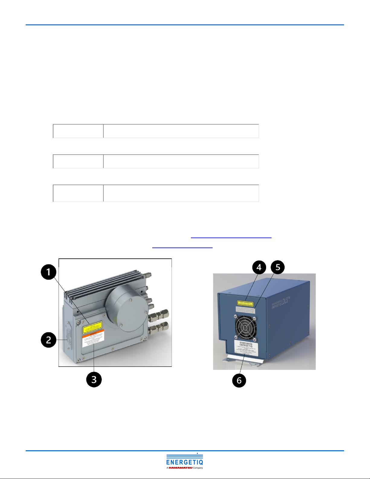
3.2 System Description ..................................................................................................................................... 12
3.3 Physical Specifications ................................................................................................................................ 15
3.4 Utility Requirements................................................................................................................................... 15
3.5 Environmental Requirements ..................................................................................................................... 15
3.6 Remote Interface ........................................................................................................................................ 15
3.7 External Interlock Connection..................................................................................................................... 16
Chapter 4. EQ-77X Setup........................................................................................................................................ 17
4.1 Connections................................................................................................................................................ 17
4.1.1 Electrical Power ........................................................................................................................................... 17
4.1.2 Purge Gas..................................................................................................................................................... 17
4.1.3 Cooling Fluid ................................................................................................................................................ 17
4.1.4 Optical Interface .......................................................................................................................................... 18
4.1.5 Signal Connections ...................................................................................................................................... 18
4.1.6 Lamp House I/O........................................................................................................................................... 19
4.1.7 RS-485 Interface .......................................................................................................................................... 19
4.2 Installation Procedure................................................................................................................................. 19
4.3 Chiller Information ..................................................................................................................................... 20
Chapter 5. EQ-77X Operation................................................................................................................................. 21
5.1 Startup ....................................................................................................................................................... 21
5.2 Stopping ..................................................................................................................................................... 21

Table of Contents
EQ-77X LDLS® Operation Manual 4of31
Chapter 6. Service Requirements........................................................................................................................... 22
Chapter 7. Troubleshooting Guide ......................................................................................................................... 23
7.1 Fault Indicator Block Diagram ..................................................................................................................... 23
Chapter 8. Accessories........................................................................................................................................... 24
Chapter 9. Warranty .............................................................................................................................................. 25
Chapter 10. Drawings, Schematics, and Pin Assignments ....................................................................................... 26
10.1 Dimensional Drawings .............................................................................................................................. 26
10.1.1 Controller Dimensional Drawings.............................................................................................................. 26
10.1.2 Lamp Head Dimensional Drawings ............................................................................................................ 26
10.2 I/O Connector Pin Assignment .................................................................................................................. 27
10.3 RS-485 Interface Pin Assignment............................................................................................................... 27
10.4 Remote Interface Schematic ..................................................................................................................... 28
10.5 Serial Interface Commands ....................................................................................................................... 29
Appendix A. Revision History................................................................................................................................. 31

Chapter 1. Introduction
EQ-77X LDLS® Operation Manual 5of31
Chapter 1. Introduction
The EQ-77XLaser-DrivenLightSource(LDLS®)isabroadbandlampsystemforuseinawidevarietyofapplications.
The lamp produces high brightness, broadband light from DUV wavelengths through visible and beyond. The output is
very stable, and has a long lifetime before any service is required. A simple control interface ensures ease of use.
Some of the advantages of the EQ-77Xsysteminclude:
The EQ-77Xsystemconsistsofapowersupplycontrollerunit,lampheadunit,andinterconnectingcable.Connection
to AC power is required for operation. Connection to cooling fluid is required. Connection to nitrogen purge gas is
strongly recommended for best performance.
For additional information, contact EnergetiqTechnologyTechnicalSupportServicesat+1-781-939-0763x111or
email: [email protected]om.
•
◦
Very high brightness across complete spectrum
190nm through visible and beyond
•
◦
Eliminatesneedformultiplelamps(replacesD2/Tungsten/XenonArc)
Simplified optical system
•
◦
Excellent spatial stability
Repeatable measurements
•
◦
Superior short and long term power stability
Repeatable measurements
•
◦
◦
Electrodeless operation for long life
Reducedconsumablecosts
Minimal recalibration of instrument

Chapter 2. Safety and Compliance
EQ-77X LDLS® Operation Manual 6of31
Chapter 2. Safety and Compliance
2.1 General Precautions
TheoutputbeamfromtheEQ-77X should be blocked when not in use with an electronic shutter or other appropriate
beamblockingdevice.DuetothepossibilityofgeneratingozonewithsomemodelsofEQ-77X when ambient oxygen
is exposed to short wavelength light, the beam should always be enclosed in an appropriate beam pipe, tube, or
enclosed space. We recommend purging any beam transport space with dry nitrogen gas.
TheEQ-77X source must also be cabled correctly and connected to a power source with a protective earth ground
prior to operation.
Refer to Chapter4.EQ-77XSetupfordetailsofthefacilitiesconnections.
There are no user-serviceable parts inside the EQ-77X.Foranyproblemsencounteredduringoperation,please
contactEnergetiq for assistance. If there is a component failure, do not attempt to open the power supply controller
or lamp head enclosure of the EQ-77X.
The EQ-77X utilizes a quartz lamp containing a high-pressure gas fill. Explosion of the lamp and possible injury from
flying fragments can occur if the lamp is mishandled.
Do not open the enclosure of either the lamp head or the power supply controller. Dangerous invisible infrared
laser beams and hazardous voltages exist inside the lamp head. Opening the chassis both voids the warranty and
exposestheusertodangerousradiationandhazardousvoltages.
This AC cord supplied is for EQ-77X only. This AC cord cannot be used with other electrical equipment.
The power shutdown mechanism of this laser unit is the AC power plug. Do not arrange the equipment in such a
way that becomes difficult to connect or disconnect the AC power plug.
WARNING: This unit emits ultraviolet (UV) radiation that is harmful to humans. Avoid exposure to the
direct or reflected output beam. Make certain that the appropriate output beam shields and optics
are in place prior to energizing the unit. All interlocks must be satisfied prior to operation; failure to
do so may lead to hazardous conditions.
CAUTION: The EQ-77XemitsdangerouslevelsofUVradiation.Evenshortexposurestoskinoreyes
may cause burns. Ensure that only authorized personnel are in the vicinity of source during
operation. Personnel in vicinity of operating source should wear protective eyewear, clothing, and
gloves. Lighted UV warning lights and signs posted on doors to lab areas may help prevent accidental
exposure.

Chapter 2. Safety and Compliance
EQ-77X LDLS® Operation Manual 7of31
WARNING: The EQ-77X utilizes an internal Class 4 IR laser capable of causing severe injury to eyes or
skin. Do not open or attempt to service this unit. Contact Energetiqregardinganyproblemswiththe
unit.
WARNING:Whenworkingneartheemittedlight,alwayswearprotectivedevices(conformingtoISO
4007/4849/4850/4854/4855 or equivalent regulations). The lamp installed in this housing emits intense ultraviolet
rays, which are harmful to the eyes and skin. Looking directly into the emitted light or allowing the light to fall on the
skinwilldamageeyesightorcauseskinburns.
WARNING: If the equipment is used in a manner not specified by the manufacturer, the protection provided by the
equipment may be impaired.
The power supply must be properly grounded by the outlet to prevent electrical shocks.
Securely plug in the power supply connector to avoid looseness or play. Loose connections may result in faulty
operation.
This product is designed and tested for use in an industrial environment. If this product is used in residential areas,
EMI (electro-magnetic interference) may occur. This product must not be used in residential areas.
This device complies with part 15 of the FCC Rules. Operation is subject to the following two conditions: (1) This
device may not cause harmful interference, and (2) this device must accept any interference received, including
interference that may cause undesired operation.
Note: This equipment has been tested and found to comply with the limits for a Class A digital device, pursuant to
part 15 of the FCC Rules. These limits are designed to provide reasonable protection against harmful interference
when the equipment is operated in a commercial environment. This equipment generates, uses, and can radiate
radio frequency energy and, if not installed and used in accordance with the instruction manual, may cause harmful
interference to radio communications. Operation of this equipment in a residential area is likely to cause harmful
interference in which case the user will be required to correct the interference at his own expense.
2.2 Definition of Equipment and Document Symbols and Designations
DonotoperatetheEQ-77X if the covers are removed or is defective in any way. Contact Energetiqifanyproblems
with the equipment are suspected.
The EQ-77X utilizes a quartz lamp containing a high-pressure gas fill. Explosion of the lamp and possible injury from
flying fragments can occur if the lamp is mishandled.
Do not open the enclosure of either the lamp or the controller. Dangerous invisible infrared laser beams and
hazardous voltages exist inside the lamp. Opening the chassis both voids the warranty and exposes the user to
dangerous radiation and hazardous voltages.

Chapter 2. Safety and Compliance
EQ-77X LDLS® Operation Manual 8of31
CAUTION: controls or adjustments or performance of procedures other than those specified herein may
result in hazardous radiation exposure.
WARNING:InvisiblelaserradiationavoideyeorskinexposuretodirectorscatteredradiationClass1laser
product.
Alternating current
TheEQ-77X is a Class 1 Laser Product. All appropriate laser safety measures should be in place before operating the
system. Consult your facility's laser safety officer. Laser protective eyewear should be worn at all times while operating
thesystem.
For further safety information, refer to ANSI Z136.1 Standard for Safe Use of Lasers, available from Laser Institute of
America (www.lia.org).
2.3 Laser Information
The EQ-77Xusesapatented*laserdrivesystemtoexciteaplasmathatradiatesintheUVaswellasthevisiblebands.
A class 4 laser is located in the lamp head enclosure. The optical configuration of the lamp head ensures that the
direct laser beam cannot exit the unit. The EQ-77XlaserproductisdesignatedasClass1duringallnormaloperation.
Theparametersofthenon-accessibleinternallaseraregivenbelowinthetableEmbedded Laser Parameters.
Parameter Value
Wavelength 974 nm
Emission Type CW
Laser Power for classification <36 mW via 7mm measurement aperture
Beam Diameter ~25 mm at aperture
Divergence >100 mRad
Transverse Beam Mode Diffuse
No regular maintenance is required for the EQ-77X. Any service to the system must be performed only by factory
authorized and trained technicians. To avoid injury, under no circumstances should the user open or modify the lamp
head or power supply controller enclosure.
The unit must not be operated if the covers are removed or it is defective in any way. Contact Energetiqifany
problems with the equipment are suspected.
Embedded Laser ParametersTable 1.

Chapter 2. Safety and Compliance
EQ-77X LDLS® Operation Manual 9of31
◦
◦
◦
* US 7435982, 7786455, 8525138, 8969841, 9048000, 9185786 ; Japan 5410958, 5628253; Korea 10-1507617; UK GB2450045;
others pending
2.4 EMC Compliance Standards
Criteria A
Light intensity Maintain at least 50% light intensity.
Criteria B
Light intensity The light intensity must not be zero.
Criteria C
Light intensity It shall be restored to normal by the operator after the
test.
2.5 Labels and Safety Notification
Thefollowingsafetylabelsappearontheproduct.ThefigureEQ-77XSafetyLabelLocationsshowsthelocationof
eachlabelontheEQ-77XsystemandthetableSafety Label Meanings describes their meanings.
•IEC 61326-1 Emission Limits: CISPR 11, Group 1, Class A
•Immunity Requirements:Table2
•Performance Level:
EQ-77XSafetyLabelLocationsFigure 1.

Chapter 2. Safety and Compliance
EQ-77X LDLS® Operation Manual 10of31
Label # Label Picture Description
1Non-interlockedhousinglabel–notifiesofapotential
hazard when covers are removed
2
Manufacturer’sidentificationlabelonlamphouse–gives
themanufacturer’snameandaddress,andthemodel,
serial number, and date of manufacture of the equipment.
3UVHazardwarninglabel–indicateshazardouslevelsof
UV light are present.
4Explanatorylabel–statestheclassificationofthelaser
product.Class1isthelowesthazardlevelclassification.
5Certificationlabel–statesthattheequipmenthasbeen
tested and verified to meet the standards indicated
6
Manufacturer’sidentificationlabeloncontroller–gives
themanufacturer’snameandaddress,andthemodel,
serial number, and date of manufacture of the equipment.
2.6 Safety Interlocks
TheEQ-77X is equipped with interlocks to prevent operation of the device when any of the following conditions are
present:
Safety Label MeaningsTable 2.
•An external interlock is open
•No bulb is installed

Chapter 2. Safety and Compliance
EQ-77X LDLS® Operation Manual 11of31
2.7 External Interlocks
Externalinterlockpinsareprovidedforthecustomer’suse.Anysuitablenormallyopencontactorsolid-stateswitch
can operate the interlock circuit. The contact or switch should be rated for 80mA minimum at 5VDC.
The interlock circuit must be connected to enable the operation of the unit. Should the interlock connection open
duringoperationorstandby,thesourceisimmediatelydisabled,andalllightoutputfromtheapertureceases.
2.8 Correct Disposal of the Unit
When the EQ-77Xhasfinallybeenremovedfromservice,observealllocalenvironmentalregulationsforproper
disposal.

Chapter 3. Preparation of System
EQ-77X LDLS® Operation Manual 12of31
Chapter 3. Preparation of System
3.1 Unpacking Guide
Start by inspecting all parts of the system for completeness and any damage incurred in shipping. The EQ-77X shipping
boxshouldcontain:
Required
Optional
If any part is missing or appears damaged, contact Energetiqimmediately.Donotattempttosubstituteanyparts.
Therearenouser-serviceablepartsinsidetheEQ-77Xlampheadorpowersupplycontrollerunit.
3.2 System Description
TheEQ-77X system consists of a power supply controller, lamp head, controller-to-lamp-head interconnect cable (not
shown), and power input cable (not shown). I/O interface connections (also not shown) are provided by the user.
The following sections provide descriptions of the system components and controls, and give an overview of their
functions. Refer to Chapter4.EQ-77XSetupformoredetailedinformation.
•EQ-77Xpowersupplycontrollerunit
•EQ-77Xlampheadunit
• Blackinterconnectingcablefromlampheadtopowersupplycontroller(21-pinmixedD-sub)
•EQ-99-RC remote control module with interlock connector
•I/O cable with 15 pin D- connector at each end
EQ-77XControllerFigure 2.

Chapter 3. Preparation of System
EQ-77X LDLS® Operation Manual 13of31
# Component Description
1Power input connector This is an IEC 320 inlet connector for AC power input. See
4.1.1 Electrical Powerfordetailedinformation.
2Status indicator SeethetableStatus Indicator LED Functionsforalistof
descriptions.
3I/OInterfaceconnector Provides access to control and status signals.
4Lamp control connector (21-pin mixed D-
sub)
Provides various power and control signals to/from the lamp
head module. No other connector or cable may be used with
theEQ-77X other than the one supplied.
5RS-485 Connector (9-pin D-sub)
Connector for optional RS-485 interface. See 10.3 RS-485
Interface Pin Assignmentforelectricaldetailsand
commands.
LocatedontheEQ-77XcontrollerfrontpanelareLEDsystemstatusindicators.Thefunctionoftheseindicatorsis
describedbelowinthetableStatus Indicator LED Functions.
LED Label Meaning (When Lit)
POWER OK AC power is connected to the EQ-77XPowerSupplyController
LAMP ON UVLightison
LASER ON Laser power is ON and laser light is being produced within the Lamp
CONTROLLER FAULT
One of the following has occurred in the power supply controller:
LAMP MODULE FAULT
One of the following has occurred in the lamp head module:
EQ-77XControllerComponentsTable 3.
Status Indicator LED FunctionsTable 4.
•External interlock open
•Controller internal temperature too high
•Laser power not reaching setpoint
•Laser temperature fault
•Internal power supply voltage low
•Control cable not connected properly
•Lamp head internal temperature too high
•Ignition failure

Chapter 3. Preparation of System
EQ-77X LDLS® Operation Manual 14of31
# Component Description
1Nitrogen Purge Inlet These are the fittings for the nitrogen purge gas. Product use
without nitrogen purge gas will result in the buildup of ozone
(from atmospheric oxygen) and attenuate the light output in the
220-280 nm band, as well as below 200 nm in the presence of
atmospheric oxygen and water vapor.
2Nitrogen Purge Outlet
3Cooling Fluid Inlet These fittings are for connection of cooling fluid required by the
lamp.
4Cooling Fluid Outlet
5Control Connector (21-pin mixed D-
sub)
Provides various power and control signals to/from the power
supply controller. No other connector or cable may be used with
theEQ-77Xotherthantheonesupplied.
6Retroreflector Assembly Reflects radiation back to the light source.
7Lamp Window
The lamp windows at the optical output provide protection from
the high-pressure bulb inside the lamp head. An internally-
threaded SM1 adapter is provided for easy connection of optical
hardware.
EQ-77XLampHeadFigure 3.
EQ-77XLampHeadComponentsTable 5.

Chapter 3. Preparation of System
EQ-77X LDLS® Operation Manual 15of31
3.3 Physical Specifications
Dimensions (H x W x D)
Weight
3.4 Utility Requirements
3.5 Environmental Requirements
Operating
Transport
3.6 Remote Interface
Digital Inputs
•Lamp Head: 128 x 175 x 102 mm (5.0 x 6.9 x 4.0 in)
•Power Supply Controller: 152 x 250 x 132 mm (6.0 x 9.8 x 5.2 in)
•Lamp Head: 2.2 kg (4.9 lb)
•Power Supply Controller: 2.9 kg (6.5 lb)
• Electrical:100–240V~+/-10%,50/60Hz,350W(Fuse:F5AL250V)
•
◦
PurgeGas:Recommended.Cleandrynitrogen,grade4.8orhigher,filteredto5um,20psig(0.14MPa)supply
pressure
Fittings: 4mm push-to-connect
•
◦
CoolingFluid:Required.≥0.5liter/minute,18–25°C,100psig(0.69MPa)max.inletpressure
Fittings: ¼ inch Swagelok
• Ambienttemperature:15–35°C.
•Relative Humidity: non-condensing, 80% max. for temperatures up to 31 °C, decreasing linearly to 50% max. at
35 °C.
•Pollution Degree 2 (normally only non-conductive pollution; occasional, temporary condensation possible).
•Overvoltage Category II
•Indoor use only.
•Operating altitude 2,000 m max.
•IP Code IP20
• Temperature:-5–70°C.
•Relative Humidity: non-condensing, 95% max.
•Type: Optocoupler LED
•Logic: Active High
•Input voltage: 5VDC
•Input current: 8 mA

Chapter 3. Preparation of System
EQ-77X LDLS® Operation Manual 16of31
External Interlock Input Only (pin 13)
Digital Outputs
Power
3.7 External Interlock Connection
Externalinterlockpinsareprovidedforthecustomer’suse(see4.1 Connectionsfor connection details). Any suitable
normally open contact or solid-state switch can operate the interlock circuit. The contact or switch should be rated for
8mA minimum at 5VDC.
The interlock circuit must be connected to enable the operation of the unit. Should the interlock connection open
during operation or standby, the source is immediately disabled, and all light output from the aperture ceases.
•Type: Relay Coil
•Logic: Active High
•Input voltage: 5VDC
•Input current: 80mA
•Type: Open collector to ground (digital common)
•Logic: Active Low
•Voltage: 30VDC max
•Sink current: 8mA max
•Voltage: 5VDC, referenced to digital common
•Current: 50 mA maximum

Chapter 4. EQ-77X Setup
EQ-77X LDLS® Operation Manual 17of31
Chapter4.EQ-77XSetup
4.1 Connections
InstallationoftheEQ-77X consists of connecting electrical, cooling fluid, and purge gas supplies, as well as connecting
thelampheadmoduletotheuser’sequipment.Read4.2 Installation Procedure first before making any connections.
4.1.1 Electrical Power
TheEQ-77Xrequires100–240V~,50/60Hzinputvoltage.Powerconsumptionis350Wmaximumduringnormal
operation. Some OEM versions have higher current requirements.
4.1.2 Purge Gas
It is strongly recommended that nitrogen purge gas is used during operation of the EQ-77Xsystem.Foroptimal
productperformance,nitrogengaspurgingoftheEQ-77Xsystemisrequiredduringoperation.Ifnitrogenpurgegasis
not used, shorter lifetime and faster output degradation (especially in the ultraviolet wavelength range) is expected.
Product use without nitrogen purge gas will result in the buildup of ozone (from atmospheric oxygen) and attenuate
the light output in the 220-280 nm band, as well as below 200 nm in the presence ofatmospheric oxygen and water
vapor.
The purge port fitting is a push-to-connect type, sized for 4mm O.D. tubing.
Clean and dry nitrogen from either a Dewar or research-grade N2 bottle is recommended. Do not use any other purge
gas. Grade 4.8 or higher gas purity is recommended to maintain cleanliness of the optics, and gas should be filtered to
<5um. Supply pressure should be 20 psig (0.14 MPa). With a 20 psig inlet pressure, the EQ-77Xwillconsume
approximately 0.5 slm of flow.
4.1.3 Cooling Fluid
Coolingfluidfittingsare1/4-inchSwagelokfemale.Acoolantflowrateof≥0.5liter/minuteisrequired.Inlet
temperature should be between 18°C and 25°C.
Care must be taken when making connections to avoid damage to the fittings and tubing. Two wrenches must always
beused–onetoholdthefittingbody,andanothertotightenthenut.SeethefigureFluid Fittingsbelowformore
details.
To make the connection: first insert tubing into the fitting and tighten the nut finger tight. Then tighten the nut 1-1/4
turns from the finger-tight position, using two wrenches as shown.

Chapter 4. EQ-77X Setup
EQ-77X LDLS® Operation Manual 18of31
4.1.4 Optical Interface
See 10.1 Dimensional Drawingsfordimensionaldrawingsofthelamp.
4.1.5 Signal Connections
TheEQ-77XiscontrolledthroughtheremoteI/Oconnector.
10.2 I/O Connector Pin Assignmentgivesthepinassignmentsandfunctionsforthisinterface.Connecttotheuser’s
control system using a suitable cable. Mating connector is a standard high-density 15-pin d-sub male (for example,
Amp part no. 748364-1 with contacts 1658670-2).
Optionally, connect a model EQ-99-RC remote control module to the I/O connector using the supplied cable. The
EQ-99-RC is shipped with an interlock jumper plug installed. To use the remote interlock function, connect a remote
contact or solid-state switch across pins 1 and 3. Mating connector is a standard 3-pin mini-DIN, CUI Inc. part no.
MD-30orequivalent.SeethefigureEQ-99-RC Remote Control Rear Panelbelowforpinconnections.
Fluid FittingsFigure 4.

Chapter 4. EQ-77X Setup
EQ-77X LDLS® Operation Manual 19of31
UserI/OcanbepoweredeitherbytheEQ-77Xinternalisolatedpowersupply,oranexternalsupply.
10.4 Remote Interface Schematicshowsconnectionschematicsforbothconfigurations.
4.1.6 Lamp House I/O
The black 21-pin mixed D-sub cable is used to connect the lamp head to the power supply controller. This cable should
be connected before AC power is applied to the power supply controller.
4.1.7 RS-485 Interface
Connector J2 is a standard 9-pin male d-sub. Mating connector is a standard 9-pin female d-sub (for example, AMP
partno.205203-3withcontacts1-66504-0).See10.3 RS-485 Interface Pin Assignment for pin connections.
Port settings are 9600 bps, 8 data bits, 1 stop bit, no parity, no handshaking.
InstallationoftheEQ-77Xconsistsofconnectingelectrical,coolingfluid,andpurgegassupplies,aswellasconnecting
thelampheadmoduletotheuser’sequipment.Read4.2 Installation Procedure first before making any connections.
4.2 Installation Procedure
The lamp head should be mounted with the output window on the side and the lamp mounting surface
oriented horizontally. The lamp head has been factory aligned in this position. Mounting the lamp in a different
EQ-99-RC Remote Control Rear PanelFigure 5.
1. Place the power supply controller on a stable surface. The power supply controller must be placed within 2
meters of the lamp head due to the length of the interconnecting cable. See 10.1 Dimensional Drawingsfor
dimensionaldetails.
2. Connect the lamp head unit optical output to the user equipment (after removing the window cover). The
beam should always be either directly coupled to a fiber optic cable, or enclosed in an appropriate beam pipe,
tube, or enclosed space and purged with nitrogen. Operating the source without any output target or beam
transport is not recommended, and may lead to unsafe operating conditions. Consult Energetiqforapplications
information and suggested configurations.

Chapter 4. EQ-77X Setup
EQ-77X LDLS® Operation Manual 20of31
orientation will cause the plasma position inside the bulb to shift slightly and may cause performance
variations.
Set up the lamp head unit with appropriate ultraviolet safety measures and laser light safety measures in place.
Itisrecommendedthatanyenclosureoraperture-blockinghardwareutilizeswitcheswiredtotheEQ-77X
externalinterlockcircuit.
See 10.1 Dimensional Drawingsfordimensionaldrawingsofthelamp.
The system is now ready to operate.
4.3 Chiller Information
The system must be connected to a cooling system. See Chapter 8. Accessoriesfor the recommended chiller.
3. Connect the black 21-pin mixed D-sub interconnect cable from the power supply controller to the lamp head.
4. Connect nitrogen purge gas to the lamp head. Refer to 4.1 Connectionsabove.
5. Connectcoolingfluidtothelamphead.Referto4.1 Connectionsabove.
6. Connectuser’scontrolsystemtotheI/Ointerfaceconnectorper10.2 I/O Connector Pin Assignment.
7. Alternately, if using the EQ-99-RC remote control module, place it on a clean rigid surface. Install the supplied
15-pincablefromthepowersupplycontrollertotheEQ-99-RC.
8. ConnectACinputpowersourcetothepowersupplycontrollerunit.
Table of contents
Other Hamamatsu Lighting Equipment manuals
Popular Lighting Equipment manuals by other brands

Ltech
Ltech SE-20-250-1000-W2D2 quick start guide

Eaton
Eaton HALO E7 TAT Non-IC New Construction Series instructions

Coleman
Coleman 830-500 user guide

Starling Technologies
Starling Technologies Pocket Spin Drift instruction manual

Forme
Forme Studio manual

High End Systems
High End Systems EC-1 installation guide