Hameg HM 604-2 User manual

Subject to change without notice
2
1. Ge eral I formatio ............................................................... 6
1. 1. Symbols used for the instrument ......................................... 6
1. 2. Tilt handle .............................................................................. 6
1. 3. Safety hints ........................................................................... 6
1. 4. Operating Conditions ............................................................ 7
1. 5. Warranty ............................................................................... 8
1. 6. Maintenance ......................................................................... 8
Fro t pa el / Co trol eleme ts HM6042.................................. 9
2. Set-up of the i strume t ...................................................... 10
2. 1. Safety advice .......................................................................10
2. 2. General ................................................................................. 10
2. 3. Selecting the line voltage .....................................................10
2. 4. Screen settings ....................................................................11
2. 4. 1. Adjusting the trace rotation .............................................11
2. 4. 2. Adjusting Y-POS./X-POS. .................................................11
3. Performi g device tests ........................................................ 11
3. 1. Choosing the DUT type........................................................12
3. 2. Setting the test ranges ........................................................12
3. 3. Displaying curves .................................................................13
3. 4. Measuring device parameters .............................................14
3. 5. Using the cursor functions ...................................................14
3. 6. Memory function, component matching ............................. 15
4. Applicatio examples............................................................ 15
4. 1. Characteristic curves of a bipolar transistor.........................15
4. 2. Characteristic curves of a field effect transistor ..................16
4. 3. Component matching ..........................................................16
Table of co te ts
St.291097/Bra

Subject to change without notice 3
Instruments
®
HM6042
14.12.1995
-
-
Ke li ie schreiber / Curve Tracer
KONFORMITÄTSERKLÄRUNG
DECLARATION OF CONFORMITY
DECLARATION DE CONFORMITE
Name u d Adresse des Herstellers HAMEG GmbH
Ma ufacturer´s ame a d address Kelsterbacherstraße 15-19
Nom et adresse du fabrica t D - 60528 Fra kfurt
HAMEG S.a.r.l.
5, av de la République
F - 94800 Villejuif
Die HAMEG GmbH / HAMEG S.a.r.l beschei igt die Ko formität für das Produkt
The HAMEG GmbH / HAMEG S.a.r.l herewith declares co formity of the product
HAMEG GmbH / HAMEG S.a.r.l déclare la co formite du produit
Bezeich u g / Product ame / Desig atio :
Typ / Type / Type:
mit / with / avec:
Optio e / Optio s / Optio s:
mit de folge de Bestimmu ge / with applicable regulatio s / avec les directives suiva tes
EMV Richtli ie 89/336/EWG ergä zt durch 91/263/EWG, 92/31/EWG
EMC Directive 89/336/EEC ame ded by 91/263/EWG, 92/31/EEC
Directive EMC 89/336/CEE ame dée par 91/263/EWG, 92/31/CEE
Niederspa u gsrichtli ie 73/23/EWG ergä zt durch 93/68/EWG
Low-Voltage Equipme t Directive 73/23/EEC ame ded by 93/68/EEC
Directive des equipeme ts basse te sio 73/23/CEE ame dée par 93/68/CEE
A gewe dete harmo isierte Norme / Harmo ized sta dards applied / Normes harmo isées utilisées
Sicherheit / Safety / Sécurité
EN 61010-1: 1993 / IEC (CEI) 1010-1: 1990 A 1: 1992 / VDE 0411: 1994
Überspa u gskategorie / Overvoltage category / Catégorie de surte sio : II
Verschmutzu gsgrad / Degree of pollutio / Degré de pollutio : 2
Elektromag etische Verträglichkeit / Electromag etic compatibility / Compatibilité électromag étique
EN 50082-2: 1995 / VDE 0839 T82-2
ENV 50140: 1993 / IEC (CEI) 1004-4-3: 1995 / VDE 0847 T3
ENV 50141: 1993 / IEC (CEI) 1000-4-6 / VDE 0843 / 6
EN 61000-4-2: 1995 / IEC (CEI) 1000-4-2: 1995 / VDE 0847 T4-2: Prüfschärfe / Level / Niveau = 2
EN 61000-4-4: 1995 / IEC (CEI) 1000-4-4: 1995 / VDE 0847 T4-4: Prüfschärfe / Level / Niveau = 3
EN 50081-1: 1992 / EN 55011: 1991 / CISPR11: 1991 / VDE0875 T11: 1992
Gruppe / group / groupe = 1, Klasse / Class / Classe = B
Datum /Date /Date U terschrift / Sig ature /Sig atur
E. Baumgart er
Tech ical Ma ager
Directeur Tech ique

Subject to change without notice
4
Ge eral i formatio regardi g the CE marki g
HAMEG instruments fulfill the regulations of the EMC directive. The conformity
test made by HAMEG is based on the actual generic- and product standards.
In cases where different limit values are applicable, HAMEG applies the severer
standard. For emission the limits for residential, commercial and light industry
are applied. Regarding the immunity (susceptibility) the limits for industrial
environment have been used.
The measuring- and data lines of the instrument have much influence on
emmission and immunity and therefore on meeting the acceptance limits. For
different applications the lines and/or cables used may be different. For
measurement operation the following hints and conditions regarding emission
and immunity should be observed:
1. Data cables
For the connection between instruments resp. their interfaces and external
devices, (computer, printer etc.) sufficiently screened cables must be used.
Without a special instruction in the manual for a reduced cable length, the
maximum cable length of a dataline must be less than 3 meters long. If an
interface has several connectors only one connector must have a connection
to a cable.
Basically interconnections must have a double screening. For IEEE-bus purposes
the double screened cables HZ72S and HZ72L from HAMEG are suitable.
2. Sig al cables
Basically test leads for signal interconnection between test point and instrument
should be as short as possible. Without instruction in the manual for a shorter
length, signal lines must be less than 3 meters long.
Signal lines must screened (coaxial cable - RG58/U). A proper ground connection
is required. In combination with signal generators double screened cables
(RG223/U, RG214/U) must be used.
3. I flue ce o measuri g i strume ts.
Under the presence of strong high frequency electric or magnetic fields, even
with careful setup of the measuring equipment an influence of such signals is
unavoidable.
This will not cause damage or put the instrument out of operation. Small
deviations of the measuring value (reading) exceeding the instruments
specifications may result from such conditions in individual cases.
December 1995
HAMEG GmbH

Subject to change without notice 5
Curve Tracer HM6042
■■
■■
■Ease of Operatio
■Characterisatio a d Test of
Semico ductor Devices
■Accurate Cursor Measureme ts
■Quick a d easy Compariso
of Semico ductors
■Refere ce Data Memory
■O -Scree Display of 5 Curves
■Low Power Co sumptio
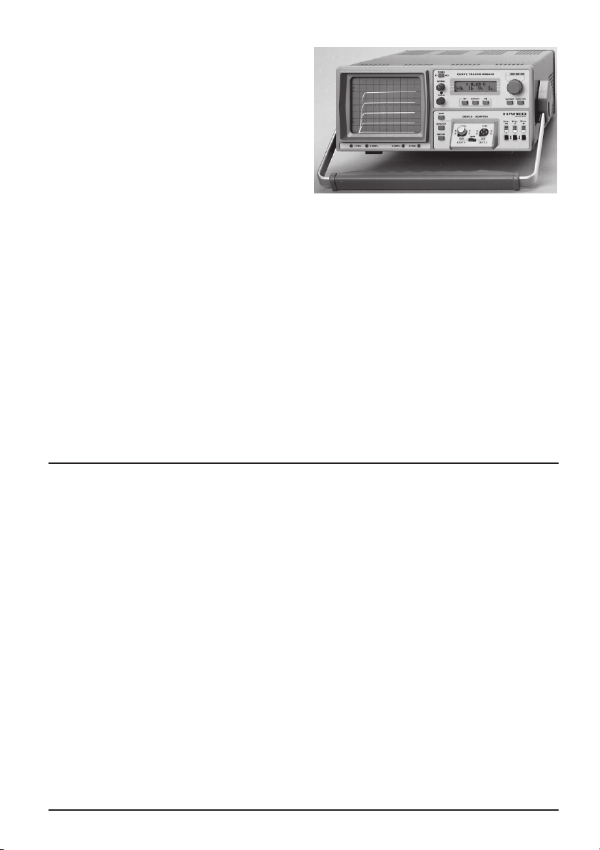
The HM6042 Curve Tracer is used to accurately display the characteristics of two and three terminal
semiconductor devices. The instrument combines ease of operation and versatile features at an
affordable price. Unlike its counterpart, the HM8042 plug-in unit, it uses a built-in CRT and an LCD to
display the characteristics of the device under test.
The HM6042 displays a set of 5 curves at a time. All numeric values and parametric data can be
read out on a 2x16 digit LCD. Device type and all relevant parameters are selected and modified by a
simple front-panel keypad entry. Collector voltage and current parameters are easily changed. A 3-
step power limiter avoids damage of the Device Under Test by excessive power.
One set of parameters can be stored in memory for comparison of one device to another or a
reference device. This feature gives substantial enhancements in productivity when matching
semiconductors. Two cursors can be moved along the displayed curves. X and Y position of the cursor
will be displayed on the screen. Basic accuracy is 2% of the measurement value. Measured parameters
are: base voltage, base current, collector current, collector voltage and Beta. The dynamic parameters
h11, h21, and h22 are calculated by the i ter al processor.
A device adapter socket with side-by-side terminals for two devices for the comparison of two
semiconductors is supplied with the instrument.
The HM6042 is remarkably easy to operate. This makes the instrument also ideally suited for
educational use.
Specificatio s
(Reference Temperature 23°C ± 1°C)
Measureme t Ra ges
3 Voltage Ra ges:
Collector/Drain Voltages ≤2V, 10V, 40V ±5%
3 Curre t ra ges:
Collector/Drain Currents ≤ 2mA, 20mA, 200mA ±5%
3 Power Ra ges:
Output Power ≤0.04W, 0.4W, 4W ±10%
Base-/Gate-Voltages a d Curre ts:
Ib1µA to 10mA Vbto 2V ±5% Vgto 10V ±5%
Accuracy
Accuracy of Static Values:
Vc/d ± (2% o.v.1) + 3 Dig.) Ic/d ± (2% o.v. + 3 Dig.)
Ib± (2% o.v. + 3 Dig.) Vb± (2% o.v. + 3 Dig.)
Vg± (3% o.v. + 3 Dig.)
ββ
ββ
βto 1000: ± (5 % o.v. + 3 Dig.)
to 100000: ± [(6 + 0.001 x β) % o.v. + 3 Dig.]
Accuracy of Dy amic Values:
h11 ≤1000Ω± (12% o.v. + 3 Dig.)
≥ 1000Ω
± [(12 + 0.001 meas. value) % o.v.+ 3 Dig.]
h21 ≤1000 ± (12% o.v. + 3 Dig.)
≥ 1000
± [(12 + 0.001 meas. value) % o.v.+ 3 Dig.]
y21 ≤1000mS ± (12% o.v.. + 3 Dig.)
h/y22 ≤1000mS ± (12% o.v.. + 3 Dig.)
Miscella eous
Reference measurement values can be stored for component
selection.
Cursor Measureme ts:
Si gle mode: The Cursor marks the position from which the
measurement value is calculated.
Tracki g mode: Two Cursors mark the positions, from hich
the h/y-Parameter measurement values are calculated.
Evaluatio of curves from
Diodes, Zener Diodes, NPN/PNP-Transistors,
FET/MOS-FET (N/P-Channel), Thyristors
Display: 2x16-Digit, LCD
Presentation of measurement values from a set of 5 curves
on CRT.
Ge eral I formatio
CRT: D14-364GY/123 or ER151-GH/-,
6" rectangular screen (8x10cm) internal graticule
Acceleratio voltage: approx. 2000V
Trace rotatio : adjustable on front panel
Line voltage: 100-240V AC ±10%, 50/60Hz
Power co sumptio : approx. 36 Watt at 50Hz.
Min./Max. ambient temperature: 0°C...+40°C
Protective system: Safety class I (IEC 1010-1)
Weight: approx. 5.6kg, color: techno-brown
Cabinet: W 285, H125, D380 mm
1) o.v. = of value

Subject to change without notice
6
1. Ge eral I formatio
The Curve Tracer HM6042 is easy to operate. The logical arrangement of
the controls allows anyone to quickly become familiar with the operation
of the instrument. However, experienced users are also advised to read
through these instructions so that all functions are understood. Immediately
after unpacking, the instrument should be checked for mechanical damage
and loose parts in the interior. If there is transport damage, the supplier
must be informed immediately. The instrument must then not be put into
operation.
1. 1. Symbols used for the i strume t
ATTENTION - refer to manual
Danger - High voltage
Protective ground (earth) terminal
1. 2. Tilt ha dle
To view the CRT screen from
the best angle, there are
three different positions (C,
D, and E) for setting up the
instrument. If the instrument
is set down on the floor after
being carried, the handle
automatically remains in the
upright carrying position (A).
In order to place the
instrument onto a horizontal
surface, the handle should be
turned to the upper side of
the Curve Tracer (C). For the
D position (10° inclination),
the handle should be turned
to the opposite direction of
the carrying position until it locks in place automatically underneath the
instrument. For the E position (20° inclination), the handle should be pulled
to release it from the D position and swing backwards until it locks once
more. The handle may also be set to a position for horizontal carrying by
turning it to the upper side to lock in the B position. At the same time, the
instrument must be lifted, because otherwise the handle will jump back.
1. 3. Safety hi ts
This instrument has been designed and tested in accordance with IEC
Publication 1010-1, Safety requirements for electrical equipment for
measurement, control, and laboratory use. The CENELEC regulations EN

Subject to change without notice 7
61010-1 correspond to this standard. It has left the factory in a safe
condition. This operating manual contains important information and
warnings that have to be followed by the user to ensure safe operation
and to retain the Curve Tracer in a safe condition. The case, chassis and all
measuring terminals are connected to the protective earth contact of the
appliance inlet. The instrument operates according to Safety Class I (three-
conductor power cord with protective ground conductor and a plug with
ground contact). The mains/line plug shall only be inserted in a socket
outlet provided with a protective ground contact. The protective action
must not be negated by the use of an extension cord without a protective
conductor.
The grounded accessible metal parts (case, sockets, and jacks) and the
mains/line supply contacts (line/live, neutral) of the instrument have been
tested against insulation breakdown with 2200V DC. Under certain
conditions, 50Hz or 60Hz hum voltages can occur in the measuring circuit
due to the interconnection with other mains/line-powered equipment or
instruments. This can be avoided by using an isolation transformer (Safety
Class II) between the mains/line outlet and the power plug of the device
being investigated.
Cathode-ray tubes normally emit X-rays. However, the dose equivalent
rate falls far below the maximum permissible value of 36 pA/kg (0.5mR/h).
Whenever it is likely that protection has been impaired, the instrument
shall be made inoperative and be secured against any unintended operation.
The protection is likely to be impaired if, for example, the instrument
- shows visible damage,
- fails to perform the intended measurements,
- has been subjected to prolonged storage under unfavorable conditions
(e.g. in the open or in moist environments),
- has been subject to severe transport stress (e.g. in poor packaging).
1. 4. Operati g Co ditio s
The instrument has been designed for indoor use. The permissible ambient
temperature range during operation is +10°C (+50°F) ... +40°C (+104°F).
It may occasionally be subjected to temperatures between +10°C (+50°F)
and -10°C (+14°F) without degrading its safety. The permissible ambient
temperature range for storage or transportation is -40°C (+14°F) ... +70°C
(+158°F).
The maximum operating altitude is up to 2200 m; the maximum relative
humidity is up to 80%. If condensed water exists in the instrument it
should be acclimatized before switching on. In some cases (e.g. instrument
extremely cold) two hours should be allowed before the instrument is put
into operation. The instrument should be kept in a clean and dry room and
must not be operated in explosive, corrosive, dusty, or moist environments.
The Curve Tracer can be operated in any position, but the convection cooling
must not be impaired. For continuous operation the instrument should be
used in the horizontal position, preferably tilted upwards, resting on the tilt
handle.

Subject to change without notice
8
The specifications stating tolerances are only valid if the instrument has
warmed up for 60 minutes at an ambient temperature between +15°C
(+59°F) and +30°C (+86°F). Values without tolerances are typical for an
average instrument.
1. 5. Warra ty
HAMEG warrants to its customers that the products it manufactures and
sells will be free from defects in materials and workmanship for a period
of two years. This warranty shall not apply to any defect, failure or damage
caused by improper use or inadequate maintenance and care. HAMEG
shall not be obliged to provide service under this warranty to repair damage
resulting from attempts by personnel other than HAMEG representatives
to install, repair, service, or modify these products.
In order to obtain service under this warranty, customers have to contact
and notify their distributor.
Each instrument is subjected to a quality test with ten-hour burn-in before
leaving the factory. Practically all early failures are detected by this method.
In the case of shipments by post, rail, or carrier it is recommended to
preserve the original packing carefully. Transport damages and damage
due to gross negligence is not covered by warranty.
In the case of a complaint, a label should be attached to the housing of the
instrument that describes briefly the faults observed. If at the same time
the name and telephone number (dialing code and telephone or direct
number or department designation) is stated for possible queries, this helps
towards speeding up the processing of warranty claims.
1. 6. Mai te a ce
Various important properties of the instrument should be checked carefully
in certain intervals to ensure that all signals and measurement results are
displayed with the accuracy on which the technical data are based.
The exterior of the instrument should be cleaned regularly with a dusting
brush. Dirt that is difficult to remove on the casing and handle, the plastic
and alloy parts, can be removed with a moistened cloth (99% water +1%
mild detergent). Spirit or washing benzene (petroleum ether) can be used
to remove greasy dirt.
The screen may be cleaned with water or washing benzene (but not with
spirit (alcohol) or solvents), it must then be wiped with a dry clean lint-free
cloth. Under no circumstances may the cleaning fluid get into the
instrument. The use of other cleaning agents can attack the plastic and
paint surfaces.

Subject to change without notice 9
Fro t pa el / Co trol eleme ts HM6042
(1) POWER
Power switch (mains).
(2) INTENS
Adjust the beam intensity.
(3) FOCUS
Adjust the beam sharpness.
(4) DISPLAY (LCD)
Indicates measurement results
and parameters.
(5) ← → ← →
← → ← →
← → (push butto s)
Select the parameters to be measured
(5) MEMORY (push butto )
Store measured values and enable
compare function
(6) CURSOR (push butto )
Move cursor from curve to curve.
(7) (LED bar)
Indicates the selected cursor function.
(8) Tune test voltages and currents.
(9) ↕ ↕
↕ ↕
↕ FUNCTION (push butto )
Select one of the cursor functions.
(10)INT. LCD
Adjust the contrast of the LCD.
(11/12) Y-POS X-POS
Adjust the trace in vertical and
horizontal position.
(13)TR
Adjust the trace rotation.
(14)DUT (push butto )
Start/stop test, connect/disconnect
the Device Under Test
(15)BIP/FET (switch)
Select between bipolar and field
effect transistor/diode.
(16)NPN/PNP (switch)
Select between NPN and PNP
transistors.
(17)E/S; C/D; B/G (jacks)
Mechanical and electrical connection
for the DEVICE ADAPTER.
(18)200mA, 20A, 2 mA (LED bar)
Indicates selected max. test current
(19)Imax. (push butto s)
Select max. test current.
(20)40V, 10V, 2V (LED bar)
Indicates selected max. test voltage
(21)Vmax. (push butto s)
Select max. test voltage.
(22)4W, 0.4W, 0.04W (LED bar)
Indicates selected max. test power.
(23)Pmax. (push butto s)
Select max. test power.

Subject to change without notice
10
2. Set-up of the i strume t
2. 1. Safety advice
Due to its measuring technique voltages up to 50 V are present at the 4
mm banana jacks, marked as E/S, C/D, and B/G. Therefore, it is assumed
that the HM6042 will only be operated by qualified personnel which is
acquainted with the danger involved.
2. 2. Ge eral
The HM6042 provides DC parameter characterization of 2- and 3-lead
semiconductor devices like transistors, diodes and MOSFETs. Five
characteristic curves displayed on the CRT’s screen and digitized to be
used for the calculation and indication of ten different parameters.
Depending on the parameter to be measured one or two cursors enable
the user to precisely select the point of measurement on one of the curves.
The microprocessor-operated instrument is extremely versatile, yet
remarkably easy to operate. Most of the instrument set-ups are done
automatically by the instrument according to the selected measuring
function.
To use the HM6042 no special expertise is required. The instrument is
easy to set-up and operation is straightforward. Nevertheless, a few basic
guidelines should be followed in order to ensure problem-free operation of
the curve tracer.
2. 3. Selecti g the li e voltage
The instrument is able to operate with mains/line voltages of 115V AC and
230V AC. The voltage selection switch is located on the rear side of the
instrument and indicates the voltage as set. The desired voltage can be
selected using a small screwdriver.
Remove the power cable from the wall outlet prior to making any changes
to the voltage setting. Fuses have to be replaced by fuses with an
appropriate value (see table below) prior to connecting the power cable.
Both fuses are accessible by removing the fuse cover located above the 3-
pole power connector. The fuse holder can be released by pressing its
plastic retainers with the aid of a small screwdriver. The retainers are located
on the right and left side of the holder and must be pressed towards the
center. The fuse(s) then can be replaced by pressing it/them in until locked
on both sides. The use of patched fuses or a short-circuited fuse holder is
not permissible; HAMEG assumes no liability for any damage caused as a
result of incorrect fuse usage; all warranty claims become null and void.
Fuse type:
Size 5 x 20 mm; 250 V AC;
Must meet IEC specification 127,
Sheet III (or DIN 41 662 or DIN 41 571, sheet 3).
Time characteristic: time lag
Line voltage 115 V~ ±10 %: Fuse rating: T 315 mA
Line voltage 230 V~ ±10 %: Fuse rating: T 160 mA

Subject to change without notice 11
2. 4. Scree setti gs
2. 4. 1. Adjusti g the trace rotatio
Due to influences of the magnetic earth field it may be necessary to
compensate an angular misalignment of the trace. To adjust the trace into
its horizontal position (in parallel to the bottom grid line) turn the TR
potentiometer (13) located below the CRT screen with a small screwdriver.
The DUT function may not be activated during this procedure.
2. 4. 2. Adjusti g Y-POS./X-POS.
Normally the readjustment of the X and Y position of the trace is not
necessary. However, if the left end of the trace is not aligned to the lower
left corner of the grid you should adjust it to start at this point. To perform
this procedure use the Y-POS. and the X-POS. screws, which are located
below the CRT screen at the front panel of the instrument.
3. Performi g device tests
As soon as the HM6042 is switched on, a baseline is visible at the CTR
screen as long as no DUT (Device Under Test) is inserted. A bright spot on
the line indicates the current cursor position.
The standard device adapter, as supplied with each HM6042, is to be
mounted to the instrument using the banana jack combination (17) at the
front panel of the instrument. The terminals are designated as E/S (Emit-
ter/Source), C/D (Collector/Drain), and B/G (Base/Gate).
This adapter is able to carry two DUTs; with the help of the instrument’s
memory function (see chapter 4. 3) and the device adapter’s toggle switch
device selections and component matching tests can be performed easily.
On request other device adapters are available from HAMEG to be used
on the HM6042 instrument.
If the standard device adapter is not suitable for special test purposes a
DUT can be connected to the terminals using ordinary test cables. Their
maximum length is limited to 25 cm each. The measurement accuracy of
the instrument however can be degraded due to hum and noise on the
cables. The use of shielded cables is not recommended because of their
relatively high stray capacitance.
When using single wire connections extreme care has to be taken for
safety purposes.
For testing diodes please use terminal E and C (17) and set the BIP/FET
switch (15) to position FET (locked).
To start a test the push button DUT (14) has to be pressed. Immediately,
the value of the selected parameter appears on the LCD.

Subject to change without notice
12
The instrument can be toggled from its active to its inactive state by pressing
the DUT key repeatedly; simultaneously the DUT will be disconnected from
the internal test circuitry. The inactive state is indicated on the LCD by the
message -off-.
3. 1. Choosi g the DUT type
The HM6042 has to be set-up according to the type of DUT (Device Under
Test) to be proved.
To test NPN bipolar transistors switch BIP/FET (15) and switch NPN/PNP
(16) has to be in released position. When working with PNP transistors
switch NPN/PNP (16) has to be set into the locked position. As usual, the
measurement is performed using the common-emitter circuit.
To test FETs set switch BIP/FET (15) into the locked position.
Diodes are tested with the same set-up as FETs using terminals E and C.
3. 2. Setti g the test ra ges
Through its range settings the instrument is enabled to limit the test voltage
(UCE, UDS) and the test current (IC, ID) to predefined values. The ranges for
current, voltage, and power can be selected by use of the push buttons for:
Imax (19) 200 mA 20 mA 2 mA
Vmax (21) 40 V 10 V 2 V
Pmax (23) 4.0 W 0.4 W .04 W
The corresponding LEDs (18), (20), and (22) indicate the maximum value
of the range as set. In test mode BIP the rotary knob enables the user to
adjust the base current in incremental steps according to the selected
range as defined below:
Ra ge Curre t (IB) No. of steps Curre t / step
1 0.3 µA ... 100 µA 127 0.8 µA ± 10 %
2 3 µA ... 1 mA 127 8 µA ± 10 %
3 30 µA ... 10 mA 127 80 µA ± 10 %
The base current at the indica-
ted cursor position is displayed
on the LCD with IB/IG selected
by the push buttons (← → ← →
← → ← →
← → , 5).
When FETs are under test the
rotary knob (8) allows adjus-
ting the gate voltage UGbet-
ween -10V to +10V in 256 in-
cremental steps. This means
80mV/ step approximately.
Figure 1

Subject to change without notice 13
Five curves (IC= f(UCE), ID = f(UG)) normally are displayed on the screen to
represent the characteristic behavior of a transistor under test. After
selecting the MIN or MAX setting with the push button called FUNCTION
(9) the rotary knob can be used to modify the minimum/maximum base
current/gate voltage in a sense that the five curves fit for the operating
range to be evaluated. Please consider not exceeding the current and
voltage settings beyond the DUTs power dissipation limits.
3. 3. Displayi g curves
The Imax and Vmax settings determine the operating range for the test
and define how the curves are going to be displaying on the CRT screen.
As shown in Figure 1, the upper edge of the grid represents the maximum
value of the test current (IC, ID) according to the selected range (Imax =
200mA/ 20mA/ 2mA).
The right edge of the 8 x 10
screen grid represents the
maximum value of the selec-
ted voltage range
(Vmax = 40V/ 10V/ 2V).
The display is linear along both
axes.
For example, if Vmax is set to
40V and Imax is set to 20mA
the horizontal resolution will be
4V/DIV and a vertical resolution
will be 2.5mA / DIV. Figure 2
Using the MIN or MAX function (9) and then turning the rotary knob (8)
allows you to position five characteristic curves on the screen and get the
desired diagnostic results. Care has to be taken not to supersede the safe
operating area of the device. Use the Vmax setup (22) to automatically
limit the power applied to the device.
Please ensure that the DUT
function has been activated for
enabling the measurement.
Figure 3

Subject to change without notice
14
3. 4. Measuri g device parameters
Generally, the behavior of transistors is determined by their static and
dynamic parameters. To display the different parameter values on the
display press one of the two bush buttons ← →← →
← →← →
← → (5) which are located
below the LCD.
The screen cursor (highlighted dot) indicates exactly the point on the curve
where the actual measurement happens to be done.
Please ensure that the DUT function has been activated to perform the
measurement.
The following parameters can be measured and displayed by the instrument:
Static Parameters
VB/VGBase/Gate Voltage
IB/IGBase/Gate Current
IC/IDCollector/Drain Current
VC/VDCollector/Drain Voltage
βCurrent Gain
Dy amic Parameters
h11 Short-circuit input impedance
h21 Short-circuit forward-current transfer ratio
h22 Open-circuit output conductance
y21 Short-circuit forward admittance
y22 Short-circuit output admittance
3. 5. Usi g the cursor fu ctio s
The cursor (highlighted dot) indicates the point on a characteristic curve
where the actual value is going to be digitized by the instrument. After the
HM6042 has been powered on, the cursor will appear on the third of the
five characteristic curves.
The cursor can be repositioned by using the CURSOR switch (6) or the
rotary knob (8). With the CURSOR key (6) the cursor can be moved from
one curve to the next. To move the cursor horizontally along a curve please
select on the LED function bar (FUNCTION 9, 7) and turn the rotary
knob (8) to reposition it in the desired direction.
The numerical value for the selected static parameter (5) will be displayed
on the LCD in accordance to the actual cursor position.
When choosing the option to display one of the dynamic parameters h11,
h21, or y21, a second cursor appears on the curve below. Turning the
rotary knob, now moves both cursors horizontally along their respective
curves. The HM6042 digitizes the values as required at the highlighted
positions and displays the calculated result on the LCD.
If you selected to test one of the dynamic parameters h22 or y22, the
second cursor appears on the same curve beside the original cursor. Turning

Subject to change without notice 15
the rotary knob (8) while function is activated (9, 7) will change the
position of the second cursor.
After selecting function TRK (9, 7) and turning the rotary knob, now both
cursors will be moved along the curve in their tracking mode. The HM6042
digitizes the values at the highlighted positions and displays the calculated
result for h22 or y22 on the LCD as requested.
The second cursor is only visible in the measuring mode for the dynamic
parameters and will be switched on and off by the instrument automatically.
3. 6. Memory fu ctio , compo e t matchi g
To support the easy selection of transistors (component matching), the
HM6042 provides a very helpful memory function. When pressing the
MEMORY push button (5) the instrument stores the measured parameter
internally and allows comparing the parameters of a second transistor with
the value stored in memory. The second device under test should be
mounted on the second test socket of the adapter. So, the selection of
devices related to a reference component can be simply achieved by
switching between the left and right socket of the adapter.
Thus the selection of components with respect to the displayed parameter
(i.e. IC/ID, β, h11, h22, y21, or y22) is a rather easy and time saving task.
To quit the memory function or to use another transistor as reference
component press the memory button (5) repeatedly.
4. Applicatio examples
4. 1. Characteristic curves of a bipolar tra sistor
1. Connect the device to be tested to the appropriate input.
2. Ensure the BIP/FET switch (15) is set to the BIP position.
3. Select NPN or PNP as appropriate with the NPN/PNP switch (16).
4. Select the appropriate range for the maximum current (Imax) (19),
maximum voltage (Vmax) (21), and maximum power Pmax (23).
5. Press the DUT switch (14). Five curves (see Figure 1 or 2) now will be
visible on the screen.
Components under test can have higher temperatures. Please be careful
when handling components having been connected to the test
instrument.
6. The vertical position of the curves IC= f(UCE) is determined by the base
current IB as parameter and can be adjusted stepwise by turning the
rotary knob (8) while FUNCTION (9, 7) is set to MAX or MIN. With
MAX selected base current for the top curve will be set, with MIN
selected that for the bottom curve. The three curves between these
two are going to be displayed in equal distances.
After the HM6042 is powered on, the base current is set to its minimum
value.

Subject to change without notice
16
7. Use the cursor functions (FUNCTION (9), CURSOR (8)) and choose the
parameter to be calculated by the instrument and displayed on the LCD
(← →, ← →,
← →, ← →,
← →, 5) by pressing the appropriate keys.
4. 2. Characteristic curves of a field effect tra sistor
Testing a FET is similar to that for a bipolar transistor with respect of the
following exceptions:
The BIP/FET switch has to be set to the FET position.
The vertical position of the curves ID= f(VDS) is determined by the gate
voltage (UG) parameter and can be adjusted stepwise by turning the rotary
knob (8) with FUNCTION (9) set to MAX or MIN. With MAX selected the
gate voltage for the top curve
will be set, with MIN selected
that for the bottom curve. The
three curves between these
two are displayed in equal
distances.Choose the parame-
ter to be calculated and dis-
played
(← →← →
← →← →
← →,,
,,
, 5)
on the LCD
by pressing the appropriate
key until you get the expected
result.
Figure 4
Security hint
Voltages up to 50V DC can be present at the device under test
when using the following max. test voltages: VD 40V and VG
-10V. Anyone using the test equipment needs to be advised of
the possible danger and the proper precautions to be taken when
working with voltages of this level.
4. 3. Compo e t matchi g
1. Measure the desired parameter of the reference transistor (← →← →
← →← →
← →, 5),
the DUT key (14) is activated.
2. Press the MEMORY push button (5) to store the parameters of the
reference transistor and to enable the compare function. The character
? appears on the LCD, and - 0 - is displayed as the value.
3. Press the DUT push button once more and insert the transistor to be
tested into the second socket of the adapter. Now toggle the adapter’s
switch to connect the second component to the instrument.
4. Press the DUT button again. Now, the numerical difference between
the reference and the actually measured value of the selected parameter
will be displayed on the LCD.
Repeat steps 3. and 4. to test other components for matching.
5. Press the MEMORY push button again to return the test set to normal
operation.
Other manuals for HM 604-2
2
Table of contents
Other Hameg GPS manuals