Hammer N2-38 User manual
Keep this manual handy and in good condition for continual reference!
Operating Manual
Bandsaw
N2-38 / N3800 / N4400
Dok.ID: 500033-901_02 • Englisch • 2023-05-31
GER = Original operating manual language
Other languages = Translation of the original operating manual
Download your local language
http://fg.am/ba-manuals
DE EN FR
PL SVROIT
DA
NL
ES ETCZ
LV SL
FI
PT
HU
RU

2
!
HAMMER
FELDER KG
KR-Felder-Straße 1, 6060 Hall in Tirol, AUSTRIA
+43 (0) 5223 / 58 50 0
+43 (0) 5223 / 56 13 0
info@felder-group.com
www.felder-group.com
Bandsaw
N2-38 / N3800 / N4400
A product of the FELDER GROUP!
For the safety of all personnel, it is necessary to study this manual thoroughly before assembly and
operation. This manual must be kept in good condition and should be considered as part of the machine.
Furthermore, the manual must be kept to hand and within the vicinity of the machine so that it is accessi-
ble to operators when using, maintaining or repairing the machine.
Attention! The machine must be inspected immediately upon arrival. If the machine has been damaged
during transport, or if any parts are missing, a written record of the problems must be submitted to the
forwarding agent and a damage report compiled. Also be sure to notify your supplier immediately.
Note: Year of construction
The machine number of this machine will be printed on the cover sheet of this operating manual..
The final two digits of the machine number show the year of construction of this machine..
e.g. XXX.XX.XXX.22 -> Year of construction 2022

3
Bandsaw
N2-38 / N3800 / N4400

4
Bandsaw
N2-38 / N3800 / N4400
Content
1 General ................................................................................................6
1.1 Symbol legend ................................................................................................ 6
1.2 Information about the manual ........................................................................... 6
1.3 Copyright ....................................................................................................... 6
1.4 Liability and warranty ...................................................................................... 7
1.5 Warranty notice .............................................................................................. 7
1.6 Spare parts ..................................................................................................... 7
1.7 Disposal ......................................................................................................... 7
2 Safety ..................................................................................................8
2.1 Intended use ................................................................................................... 8
2.2 Manual contents .............................................................................................. 8
2.3 Making changes and modifications to the machine .............................................. 9
2.4 Responsibilities of the operator .......................................................................... 9
2.5 Personnel requirements ..................................................................................... 9
2.6 Work safety .................................................................................................... 9
2.7 Personal protective equipment ......................................................................... 10
2.8 Machine hazards .......................................................................................... 10
2.9 Other risks .................................................................................................... 11
2.10 Foreseeable misuse ...................................................................................... 11
3 Declaration of Conformity ...................................................................12
4 Specifications ......................................................................................14
4.1 Dimensions and weight .................................................................................. 14
4.2 Noise emission ............................................................................................. 14
4.3 Operation and storage conditions ................................................................... 15
4.4 Electrical connection/Drive motor .................................................................... 15
4.5 Dust Extractors .............................................................................................. 16
5. Assembly...........................................................................................17
5.1 Overview ..................................................................................................... 17
5.2 Data plate .................................................................................................... 18
5.3 Automatic braking system ............................................................................... 18
5.4 Brake system - USA model .............................................................................. 18
6 Setup and installation .........................................................................19
6.1 Safety instructions .......................................................................................... 19
6.2 Installation site requirements ............................................................................ 19
6.3 Setup ........................................................................................................... 20
6.3.1 Setting up the work table .........................................................................................20
6.3.2 Positioning the 90° end stop on the work table ...........................................................20
6.3.3 Rip fence ...............................................................................................................20
6.3.4 Positioning and levelling the machine .........................................................................21
6.4 Electrical connection ...................................................................................... 22

5
Bandsaw
N2-38 / N3800 / N4400
7 Operation ...........................................................................................23
7.1 Safety instructions .......................................................................................... 23
7.2 Blade selection and maintenance .................................................................... 24
7.3 Saw blade replacement/tension ...................................................................... 25
7.4 Tilting the table ............................................................................................. 25
7.5 Adjusting the saw blade guide ........................................................................ 26
7.5.1 Height adjustable protection device ...........................................................................26
7.5.2 Saw blade guide upper / down (Optional with the N2-38) ..........................................26
7.5.3 Saw blade guide - General guidelines ......................................................................27
7.6 Switching on the machine / Switching off the machine ....................................... 28
7.7 Authorised working techniques ........................................................................ 28
7.7.1 Longitudinal cut along the marked line .......................................................................28
7.7.2 Cutting round workpieces in the transverse direction ....................................................29
7.7.3 Cutting workpieces on the upright edge .....................................................................29
7.7.4 Longitudinal cut of narrow or thin workpieces with the longitudinal guide fence ..............29
7.7.5 Mitre cuts ...............................................................................................................30
7.7.6 Circular cuts ...........................................................................................................30
7.7.7 Diagonal cross-cut of rectangular workpieces ..............................................................30
8 Service ...............................................................................................31
8.1 Safety instructions .......................................................................................... 31
8.2 Tightening/replacing the drive belt .................................................................. 31
8.3 Replacing the rubber wearing surface of wheels................................................ 32
8.4 Cleaning and lubrication ................................................................................ 32
8.5 Direction of cut and parallelism ....................................................................... 32
8.6 Safety devices - Check efficiency ..................................................................... 33
9 Faults .................................................................................................34
9.1 Safety instructions .......................................................................................... 34
9.2 What to do if a fault develops ......................................................................... 34
9.3 What to do after rectifying the fault ................................................................. 34
9.4 Faults, causes and repairs ............................................................................... 35
10 Circuit diagrams / Spare parts ..........................................................35
Content
6
!
Bandsaw
N2-38 / N3800 / N4400
General
1 General
1.1 Symbol legend
Important technical safety instructions in this manual are
marked with symbols.
These instructions for work safety must be followed.
In all these particular cases, special attention must be
paid in order to avoid accidents, injury to persons or
material damage.
Attention! Risk of material damage!
This symbol marks instructions which, if not observed, may lead to material damage, functional failures and/
or machine breakdown!
Warning! Risk of injury or death!
This symbol marks instructions that must be followed in order to avoid harm to one‘s health, injuries, perma-
nent impairment or death!
Warning! Danger! Electric current!
This symbol warns of potentially dangerous situations relating to electric current. Not observing the safety
instructions increases the risk of serious injury or death. All electrical repairs must be carried out by a qualified
electrician!
1.2 Information about the manual
This manual describes how to operate the machine
properly and safely. Be sure to follow the safety tips and
instructions stated here as well as any local accident
prevention regulations and general safety regulations.
Before beginning any work on the machine, ensure that
the manual, in particular the chapter entitled “Safety”
and the respective safety guidelines, has been read in its
entirety and fully understood. This manual is an integral
part of the machine and must therefore be kept in the
direct vicinity of the machine and be accessible at all
times. If the machine is sold, rented, lent or otherwise
transferred to another party, the manual must accompany
the machine.
1.3 Copyright
This manual should be handled confidentially. It is
designated solely for those persons who work on or with
the machine. All descriptions, texts, drawings, photos
and other depictions are protected by copyright and
other commercial laws. Illegal use of the materials is
punishable by law.
This manual, in its entirety or parts thereof, may not
be transferred to third parties or copied in any way or
form, and its contents may not be used or otherwise
communicated without the express written consent of the
manufacturer.
Infringement of these rights may lead to a demand for
compensation or other applicable claims. We reserve all
rights in exercising commercial protection laws.
Note:
This symbol marks tips and information which should be observed to ensure efficient and failure-free operati-
on of the machine.
7
!
Bandsaw
N2-38 / N3800 / N4400
General
1.4 Liability and warranty
The contents and instructions in this manual have been
compiled in consideration of current regulations and
state-of-the-art technology as well as based on our know-
how and experience acquired over many years. This
manual must be read carefully before commencing any
work on or with this machine. The manufacturer shall not
be liable for damage and/or faults resulting from the dis-
regard of instructions in the manual. The text and images
do not necessarily represent the delivery contents.
The images and graphics are not depicted on a 1:1
scale. The actual delivery contents are dependent on
custom-build specifications, add-on options or recent
technical modifications and may therefore deviate from
the descriptions, instructions and images contained in
the manual. Should any questions arise, please contact
the manufacturer. We reserve the right to make technical
modifications to the product in order to further improve
user-friendliness and develop its functionality.
1.5 Warranty notice
The guarantee period is in accordance with national
guidelines. Details may be found on our website,
www.felder-group.com
1.6 Spare parts
If unauthorised spare parts are fitted into the machine,
all warranty, service, compensation and liability claims
against the manufacturer and their contractors, dealers
and representatives shall be rejected.
Use only genuine spare parts supplied by the manufac-
turer.
1.7 Disposal
If the machine is to be disposed of, separate the compo-
nents into the various materials groups in order to allow
them to be reused or selectively disposed of. The whole
structure is made of steel and can therefore be dis-
mantled without problem.
This material is also easy to dispose of and does not pol-
lute the environment or jeopardise public health. Interna-
tional environmental regulations and local disposal laws
must always be complied with.
Attention! Risk of material damage!
Non genuine, counterfeit or faulty spare parts may result in damage, cause malfunction or complete break-
down of the machine.
Note: The original spare parts that have been authorised for use are listed in a separate spare parts catalo-
gue, enclosed in the documentation package supplied with the machine.
Attention! Used electrical materials, electronic components, lubricants and other auxiliary substances must be
treated as hazardous waste and may only be disposed of by specialised, licensed firms.

8
!
Bandsaw
N2-38 / N3800 / N4400
Safety
The machine described in this manual is intended solely
for processing wood and similar machinable materials.
This includes all wood based panel material (e.g. Chip-
board, OSB panels, MDF, Plywood etc.), even if they are
laminated or edged with plastic or a light metal. Other
materials are cardboard, cork, bone and all rigid plastics
(thermoset plastics and thermo plastics) as long as whilst
machining them it does not lead to any risks from dust,
chips or thermal degradation products.
This information can be taken from the relevant safety
sheets
The term “proper use” also refers to correctly observing
the operating conditions as well as the specifications and
instructions in this manual.
The machine may only be operated with parts and
original accessories from the manufacturer.
Attention! Risk of material damage!
Machining materials other than wood is only permitted with the express written consent of the manufacturer.
Operational safety is guaranteed only when the machine is used for the intended purposes.
2 Safety
At the time of its development and production, the
machine was built in accordance with prevailing
technological regulations and therefore conforms to
industry safety standards.
However, hazards may arise should the machine be
operated by untrained personnel, used improperly or em-
ployed for purposes other than those it was designed for.
The chapter entitled “Safety” offers an overview of all
the important safety considerations necessary to optimise
safety and ensure the safe and trouble-free operation of
the machine.
To further minimise risks, the other chapters of this
manual contain specific safety instructions, all marked
with symbols. Besides the various instructions, there are
a number of pictograms, signs and labels affixed to the
machine that must also be heeded. These must be kept
visible and must not be removed.
2.1 Intended use
2.2 Manual contents
All those appointed to work on or with the machine must
have fully read and understood the manual before
commencing any work. This requirement must be met
even if the appointed person is familiar with the
operation of such a machine or a similar one, or has
been trained by the manufacturer.
Knowledge about the contents of this manual is a prere-
quisite for protecting personnel from hazards and avoi-
ding mistakes so that the machine may be operated in
a safe and trouble- free manner. It is recommended that
the operator requests proof from the personnel that the
contents of the manual have been read and understood.
Attention! Any use outside of the machine‘s intended purpose shall be considered improper and is therefore
not permitted. All claims regarding damage resulting from improper use that are made against the manufac-
turer and its authorised representatives shall be rejected. The operator shall be solely liable for any damage
that results from improper use of the machine.

9
Bandsaw
N2-38 / N3800 / N4400
Safety
2.3 Making changes and modifications to the machine
In order to minimise risks and to ensure optimal perfor-
mance, it is strictly prohibited to alter, retrofit or modify
the machine in any way without the express consent of
the manufacturer.
All the pictograms, signs and labels affixed to the
machine must be kept visible, readable and may not be
removed. Pictograms, signs and labels that have become
damaged or unreadable must be replaced promptly.
2.4 Responsibilities of the operator
This manual must be kept in the immediate vicinity of
the machine and be accessible at all times to all persons
working on or with the machine. The machine may only
be operated if it is in proper working order and in safe
condition. The general condition of the machine must be
controlled and the machine must be inspected for visible
defects every time before it is switched on. All instruc-
tions in this manual must be strictly followed without
reservation.
Besides the safety advice and instructions stated in this
manual, it is necessary to consider and observe local
accident prevention regulations, general safety regula-
tions as well as current environmental stipulations that
apply to the operational range of the machine.
The operator and designated personnel are responsible
for the trouble-free operation of the machine as well as
for clearly establishing who is in charge of installing,
servicing, maintaining and cleaning the machine.
Machines, tools and accessories must be kept out of the
reach of children.
2.5 Personnel requirements
Only authorised and trained personnel may work on and
with the machine. Personnel must be briefed about all
functions and potential dangers of the machine. “Spe-
cialist staff“ is a term that refers to those who – due to
their professional training, know-how, experience, and
knowledge of relevant regulations – are in a position to
assess delegated tasks and recognise potential risks. If
the personnel lack the necessary knowledge for wor-
king on or with the machine, they must first be trained.
Responsibility for working with the machine (installation,
service, maintenance, overhaul) must be clearly defined
and strictly observed. Only those persons who can be
expected to carry out their work reliably may be given
permission to work on or with the machine. Personnel
must refrain from working in ways that could harm
others, the environment or the machine itself. It is absolu-
tely forbidden for anyone who is under the influence of
drugs, alcohol or reaction-impairing medication to work
on or with the machine. When appointing personnel to
work on the machine, it is necessary to observe all local
regulations regarding age and professional status. The
user is also responsible for ensuring that unauthorised
persons remain at a safe distance from the machine.
Personnel are obliged to immediately report any irregu-
larities with the machine that might compromise safety to
the operator.
2.6 Work safety
Following the safety advice and instructions given in this
manual can prevent bodily injury and material
damage while working on and with the machine. Failure
to observe these instructions can lead to bodily injury
and damage to or destruction of the machine. Disregard
of the safety advice and instructions given in this manual
as well as the accident prevention regulations and gene-
ral safety regulations applicable to the operative range
of the machine shall release the manufacturer and their
authorised representatives from any liability and from all
compensation claims.
10
Bandsaw
N2-38 / N3800 / N4400
Safety
2.7 Personal protective equipment
When working on or with the machine, the following must be strictly observed:
Protective clothes
Sturdy, tight-fitting clothing (tear-resistant, no wide sleeves, no jewellery (rings, bracelets, necklaces, etc.)).
Persons with long hair who are not wearing a hairnet are not permitted to work on or with the machine!
It is prohibited to wear gloves while working on or with the machine.
When working on or with the machine, the following must always be worn by personnel:
Protective footwear
To protect the feet from heavy falling objects and prevent sliding on slippery floors
Hearing protection
To protect against loss of hearing
2.8 Machine hazards
The machine has undergone a hazard analysis. The
design and construction of the machine are based on the
results of this analysis and correspond to state-of-the-art
technology.
The machine is considered operationally safe when used
properly.
Nevertheless, there are some remaining risks that must be
considered.
The machine runs at high electrical voltage.
• Before carrying out any maintenance, cleaning and
repair work, switch off the machine and ensure that it
can not be accidentally switched on again.
• When carrying out any work on the electrical equip-
ment, ensure that the voltage supply is completely
isolated.
• Do not remove any safety devices or alter them to
prevent them from functioning correctly.
Warning! Danger! Electric current!
Electrical energy can cause serious bodily injury. Damaged insulation materials or defective individual compo-
nents can cause a life-threatening electrical shock.
Safety glasses
Wear safety goggles
Note: Ignition sparks may be generated during machining.
Carefully inspect workpieces for foreign matter (nails, screws) which might impair processing.

11
Bandsaw
N2-38 / N3800 / N4400
General safety rules:
• Be wary of sharp edges to avoid cutting yourself, in particular when changing the tooling.
• Risk of injury due to ejected work pieces and parts of work pieces (e.g. branches, chips).
• Risk of injury from workpiece kickback.
• Hearing damage as a result of high noise levels.
• Risk of damage to health from dust especially when working hard woods.
• Risk of injury through being crushed, cut, caught, wound up or sliced.
2.9 Other risks
Warning! Risk of injury!
Even if the safety measures are complied with, there are still certain associated risks that must be considered
when working on the machine:
Safety
General safety rules:
• Failure to follow the operation manual.
• Operating the machine, even if the operation manual is incomplete or not in the language of the country it is in.
• Placing of material or tools on the work surface.
Components and tools that are not put in their correct place or put away may be the cause of accidents!
• Usage of a tool system that is not suited for the material or the machine.
Only clamp authorised tools to the machine.
• Usage of a modified module and tool system.
Only use original manufacturer tools
• Fitting of spare parts and usage of tools and accessories that are not permitted by the manufacturer.
Use only genuine spare parts supplied by the manufacturer.
• Making changes and modifications to the machine.
• Bridging or adaptation of protective equipment.
During operation:
• Processing of workpieces that are too large or too heavy.
• Processing of very small workpieces without assistance.
Keep handling auxiliaries at hand: See chapter entitled >Operation<
• Processing of unsuitable materials such as metal.
• Processing of workpieces that are not, or insufficiently held in place.
• Processing of workpieces in the same direction as the rotation of the tool.
(Feed direction corresponds to the rotational direction of the tool.)
• Using the machine without the appropriate safety equipment.
Ensure that all safety devices have been installed properly.
• Deliberately bad or irresponsible behaviour on the machine whilst operating.
Every time the machine is being serviced:
• Service work carried out by untrained or unauthorised personnel.
• Non-compliance with maintenance guidelines.
See chapter entitled >Service - Maintenance schedule<
• Failure to observe signs of wear and damage.
2.10 Foreseeable misuse
Note:
The examples mentioned here should be used to bring the attention to the hazards that can occur, but are not
a complete list and should not be used as a legal basis.
Nevertheless, this information is provided to help the operator better assess hazards and risks.

12
Hall in Tirol, 21.01.2021 Prof. h.c. Ing. Johann Georg Felder
CEO FELDER KG
KR-Felder-Straße 1, 6060 Hall in Tirol, AUSTRIA
Bandsaw
N2-38 / N3800 / N4400
Manufacturer: Felder KG
KR-Felder-Straße 1, 6060 Hall in Tirol, AUSTRIA
Product designation: Bandsaw
Make: HAMMER
Model designation: N2-38 / N3800 / N4400
The following EC guidelines were applied: 2006/42/EC
2014/30/EU
The following harmonised norms were applied: EN ISO 1807-1: 2013
EN 60204-1: 2018
EN ISO 12100: 2010
The prototype test was carried out by: CEPROM® S.A.
Product Certification Body
NB 1802
Str.Fântânele f.n
RO-440237 Satu Mare
Conformity with the EC Machine Guidelines certified by: EG-Design Test Certificate No. 212-ET-12021
3 Declaration of Conformity
Declaration of Conformity
This EC Declaration of Conformity is valid only if the CE label has been affixed to the machine.
Modifying or altering the machine without the express written agreement of the manufacturer shall render the war-
ranty null and void.
The signatory of this statement is the appointed agent for
the compilation of the technical information
Note: Machine number
The machine number of this machine will be printed on the cover sheet of this operating manual.
EG-Declaration of Conformity
According to Machine Guidelines 2006/42/EG
We hereby declare that the machine indicated below, which corresponds to the design and construction of the model
we placed on the market, conforms with the health and safety requirements as stated by the EC guidelines (see table).

13
Bandsaw
N2-38 / N3800 / N4400
Manufacturer: Felder KG
KR-Felder-Straße 1, 6060 Hall in Tirol, AUSTRIA
Product designation: Bandsaw
Make: HAMMER
Model designation: N2-38 / N3800 / N4400
The following UK guidelines were applied: S.I. 2008/1597
S.I. 2016/1091
The following harmonised norms were applied: EN ISO 1807-1: 2013
EN 60204-1: 2018
EN ISO 12100: 2010
This Declaration of Conformity is valid only if the UKCA label has been affixed to the machine.
Modifying or altering the machine without the express written agreement of the manufacturer shall render the war-
ranty null and void.
The signatory of this statement is the appointed agent for
the compilation of the technical information
Note: Machine number
The machine number of this machine will be printed on the cover sheet of this operating manual.
Declaration of Conformity
According to UK Directive S.I. 2008/1597
We hereby declare that the machine indicated below, which corresponds to the design and construction of the model
we placed on the market, conforms with the health and safety requirements as stated by the UK guidelines (see table).
Prof. h.c. Ing. Johann Georg Felder
CEO FELDER KG
KR-Felder-Straße 1, 6060 Hall in Tirol, AUSTRIA
Hall in Tirol, 21.01.2021
Declaration of Conformity

14
LB
H
Bandsaw
N2-38 / N3800 / N4400
4 Specifications
4.1 Dimensions and weight
4.2 Noise emission
The given values are emission values and not safe work-
place values. Although there is a correlation between
emission and immission levels, it is not possible to state
whether increased safety measures are required.
Factors which can considerably influence the present
immission level at the workplace include the duration of
exposure, the character of the work area and other influ-
ences in the neighbouring area.
Acceptable workplace values may also vary from coun-
try to country. However, this information should help the
user to better assess the hazards and risks.
Depending on the installation location and other
variables, the resulting noise emission can differ by up
to 4 db (A) from the given values.
Fig. 4-1: Total size
Specifications
Machine (L x W x H) N2-38 / N3800 N4400
Total size 829 x 800 x
454 x 650 x
1750 mm 1865 mm
Package size 640 x 780 x
390 x 660 x
1820 mm 1900 mm
Net weight 150 kg 170 kg
Model L Aeq LW (A) Lpc
N2-38 / N3800 84,5 dB (A) 93,7 dB (A) 2,3 mW < 130 dB (A)
N4400 84,7 dB (A) 97,1 dB (A) 5,1 mW < 130 dB (A)
Bandsaw N2-38 / N3800 N4400
Cutting height 310 mm 310 mm
Rip capacity max. 360 mm 420 mm
- || - Rip fence 320 mm 377 mm
Saw blade length 3556 mm 3980 mm
Saw blade width 6 - 20 mm 6 - 25 mm
Saw blade speed 15,6 m/sec 15,4 m/sec
Wheel diameter 380 mm 440 mm
Table size 400 x 510 mm 420 x 575 mm
Tiltable table -5° max. +45° -10° max. +45°

15
Bandsaw
N2-38 / N3800 / N4400
Electrical connection
mains voltage according to specification plate ±10%
Safeguarding see circuit plan
Power supply cord (H07RN-F) 3G1,5 mm²/ 4Gx1,5 mm²
Triggering characteristic C
Drive motor N2-38 Alternating-current motor Three-phase current motor
Motor voltage 1x 230 V 3x 400 V
motor frequency 50 Hz 50 Hz
System of protection IP 54 IP 54
Motor power S6-40 %*)1,5 kW 1,5 kW
Drive motor N 3800 Alternating-current motor Three-phase current motor
Motor voltage 1x 230 V 3x 400 V
motor frequency 50/60 Hz 50/60 Hz
System of protection IP 54 IP 54
Motor power S6-40 %*)1,5 kW 1,5 kW
Drive motor N 4400 Alternating-current motor Three-phase current motor
Motor voltage 1x 230 V 3x 400 V
motor frequency 50/60 Hz 50/60 Hz
System of protection IP 54 IP 54
Motor power S6-40 %*)2,5 kW 2,5 kW
*) S6 = operation under load and intermittent service; 40% = relative operating factor
4.4 Electrical connection/Drive motor
The actual values can be found on the data plate.
4.3 Operation and storage conditions
Specifications
Operating/room temperature +10 to +40 °C
Storage temperature –10 to +50 °C

16
!
Bandsaw
N2-38 / N3800 / N4400
4.5 Dust Extractors
The machine has to be connected to a dust extractor. The
connection values and the position of the connection port
are shown on the picture.
The air speed at the connection point has to be a mini-
mum of 20 m/s for materials with a humidity less than
12 %.
The air speed should be increased to 25–28 m/s to ex-
tract dust from more humid materials (over 12 %).
Only flame resistant vacuum hoses can be used, conform-
ing to DIN 4102 B1 and any other safety regulations in
effect.
Fig.. 4-2: Connection ports
!Connection ports 120 mm
Specifications
Extraction connection-Ø 120 mm
Air speed 20 m/s
Min. depression 773 Pa
Volume flow min. 814 m³/h
Warning! Risk of injury! Vacuum hose must be flame-resistant and must conduct electricity! Be sure to use only
genuine Hammer vacuum hoses!
Note: As a rule, all units must be vacuumed during use. A time delayed socket is available as an accessory.

17
!
"
$
%
&
(
)
/
BP
BR
BM
BN
CN
CM
BQ
BL
BO
BU
BT
CL
CL
CL
#BS
Bandsaw
N2-38 / N3800 / N4400
5. Assembly
5.1 Overview
Fig.. 5-1: Overview
Assembly
BOGuide fence
BPSaw blade track - Adjuster hand wheel and clamping
lever
BQLock wheel - Blade guide height adjustment
BRBlade tension hand wheel
BSmitre fence (Accessories)
BTSaw blade tension indicator window
BUOn/Off switch
CLLock wheel - Wheel door
CMVacuum connector
CNTiltable table
(Adjuster hand wheel and clamping lever)
!Machine base-frame
" Upper wheel
#Lower wheel
$ Rising part of saw blade
%Falling part of saw blade
&Upper blade guide
/Lower blade guide (Optional)
*Blade guide height adjustment
)Work bench
BLWheel door
BMHeight adjustable protection device
BNTable insert
18
!
Bandsaw
N2-38 / N3800 / N4400
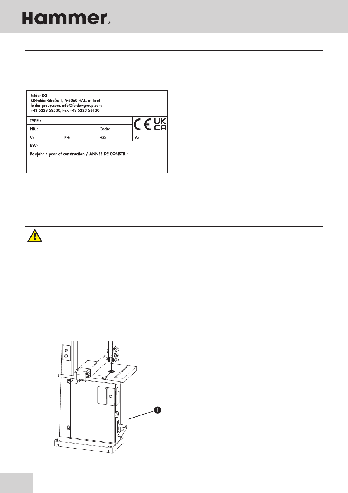
5.2 Data plate
The data plate displays the following specifications:
• Manufacturer information
• Model designation
• Machine number
• Voltage
• Phases
• Frequency
• Motor
• Power supply
• Year of construction
• Motor specifications
Fig.. 5-2: Data plate
The machine is equipped with a mechanical brake,
which guarantees that all the moveable parts will come
to a stop within 10 seconds, once the machine has been
switched off.
Les machoires du frein sont des pièces d‘usure et doivent
être contrôlées régulièrement et si nécessaire échangées,
afin que le frein fonctionne dans le délai impartit.
Please contact the FELDER KG service department, if
problems or a fault- function should occur!
5.4 Brake system - USA model
!Foot brake
Fig. 5-3: Foot brake
5.3 Automatic braking system
Your machine is equipped with an automatic braking
unit. The brake is a maintenance-free DC braking unit.
All necessary adjustments are done ex factory.
Please contact the FELDER KG service department, if
problems or a fault- function should occur!
Assembly
Warning! Risk of injury!
In the event of a power supply failure, the electric brake is deactivated. The tool can therefore not come to
a complete stop within 10 seconds.
In this case, the machine will stop without using the the automatic braking system!

19
!
!
Bandsaw
N2-38 / N3800 / N4400
Warning! Risk of injury!
Risk of injury! Keep machines, tools and accessories etc. out of the reach of children.
Vacuum hoses and electrical wires should be layed in such a way as to avoid tripping over them.
6 Setup and installation
6.1 Safety instructions
Warning! Risk of injury! Improper assembly and installation can lead to serious physical injury or equipment
damage. For this reason, this work may only be carried out by authorised, trained personnel who are familiar
with how to operate the machine and in strict observance of all safety instructions.
• Ensure that there is sufficient space to work around
the machine. Ensure there is ample distance be-
tween the machine and other solid constructions
such as a walls or other machines.
• Keep the work area orderly and clean. Components
and tools that are not put in their correct place or put
away may be the cause of accidents!
• Install the safety equipment according to the
instructions and check that it functions properly.
Setup and installation
6.2 Installation site requirements
• Operation/room temperature: +10° to +40° C
• Ensure that the work surface is sufficiently stable and
has the proper load-bearing capacity
• Provide sufficient light at the workstation
• Ensure there is sufficient clearance for or from
neighbouring workstations
Attention! Risk of material damage!
The machine may only be used in a dry and frost-free environment and may not be used outside.
Attention! Risk of material damage!
Only operate the machine in ambient temperatures from +10°C to +40°C. If the instructions are not followed,
damage may occur to bearings.
Warning! Risk of injury! An incomplete, faulty or damaged machine can lead to serious physical injury or
equipment damage. Only assemble and install the machine if the machine and its parts are complete and
intact.
Warning! Danger! Electric current!
Work on electrical fittings may only be carried out by qualified personnel and in strict observance of the safety
instructions.
The floor space around the machine must be flat, well
maintained, free of obstacles and cleared of waste mate-
rial such as chips and offcuts.

20
!
"
!#
"
"
!
$
#
Bandsaw
N2-38 / N3800 / N4400
6.3 Setup
6.3.3 Rip fence
Fig. 6-3: Rip fence
• Use a nut to mount the fence rail to the machine ta-
ble.
• Slide the premounted fence onto the track.
!Nut
"Fence rail
6.3.2 Positioning the 90° end stop on the work table
Fig. 6-2: End stop
• Disconnect the machine from the mains supply.
• Loosen the clamping lever.
• Tilt the work table until it rests on the stop screw.
• Determine the exact angle using a 90° triangle.
• If the 90° in the initial position is not correct, adjust
the stop screw accordingly.
• Check the 90° angle once the clamping lever is back
in place.
!Work table
"Clamping lever
#Fence screw
6.3.1 Setting up the work table
• The table insert and positioning pin have to be re-
moved to set up the work table.
• Thread the work table around the saw blade and
mount to the machine using SKT screws and washers.
• Re-affix the table insert and positioning pin.
Fig. 6-1: Work table
!Positioning pin
"Table insert
#Washers
$Screw
Setup and installation
This manual suits for next models
2
Table of contents
Other Hammer Saw manuals


Popular Saw manuals by other brands


EINHELL
EINHELL BFS 800E operating instructions

Hitachi Koki
Hitachi Koki C 10FSH manual

DeWalt
DeWalt DWS774 manual

MK Diamond Products
MK Diamond Products MK-100 SERIES owner's manual

Scheppach
Scheppach mss 8 Translation from the original instruction manual

King Industrial
King Industrial KC-5100C instruction manual