Hangar 9 J-3 Piper Cub User manual

TM
TM
INSTRUCTION MANUAL
Specifications:
Wingspan:. . . . . . . . . . . . . . . . . . . . . . . . . . . . . . . . . . . . . 100"
Length: . . . . . . . . . . . . . . . . . . . . . . . . . . . . . . . . . . . . . . . 64"
Wing Area: . . . . . . . . . . . . . . . . . . . . . . . . . . . . . 1350 sq. in
Weight (Approx.): . . . . . . . . . . . . . . . . . . . . . . . . . . 13-16 lbs.
Recommended Engines: 2-Cycle: 1.08–1.48
4-Cycle: 1.20–1.80
Gas: Zenoah G23cc
254 cm
154 cm
3429 sq cm
5.9 - 7.3 kg
• 100" Wingspan
• 90% pre-built
• Covered in Cub yellow WorldTex fabric covering
• Includes Scale detailing instructions
• Cub yellow fiberglass cowl included
• IMAA legal
• All hardware included

2
Table of Contents
Introduction . . . . . . . . . . . . . . . . . . . . . . . . . . . . . . . . . . . . . . . . . . . . . . . . . . . . . . . . . . . . . . . . . . . . . . . . . . . . . . . . . . . . . . . . . .3
Warning . . . . . . . . . . . . . . . . . . . . . . . . . . . . . . . . . . . . . . . . . . . . . . . . . . . . . . . . . . . . . . . . . . . . . . . . . . . . . . . . . . . . . . . . . . . .3
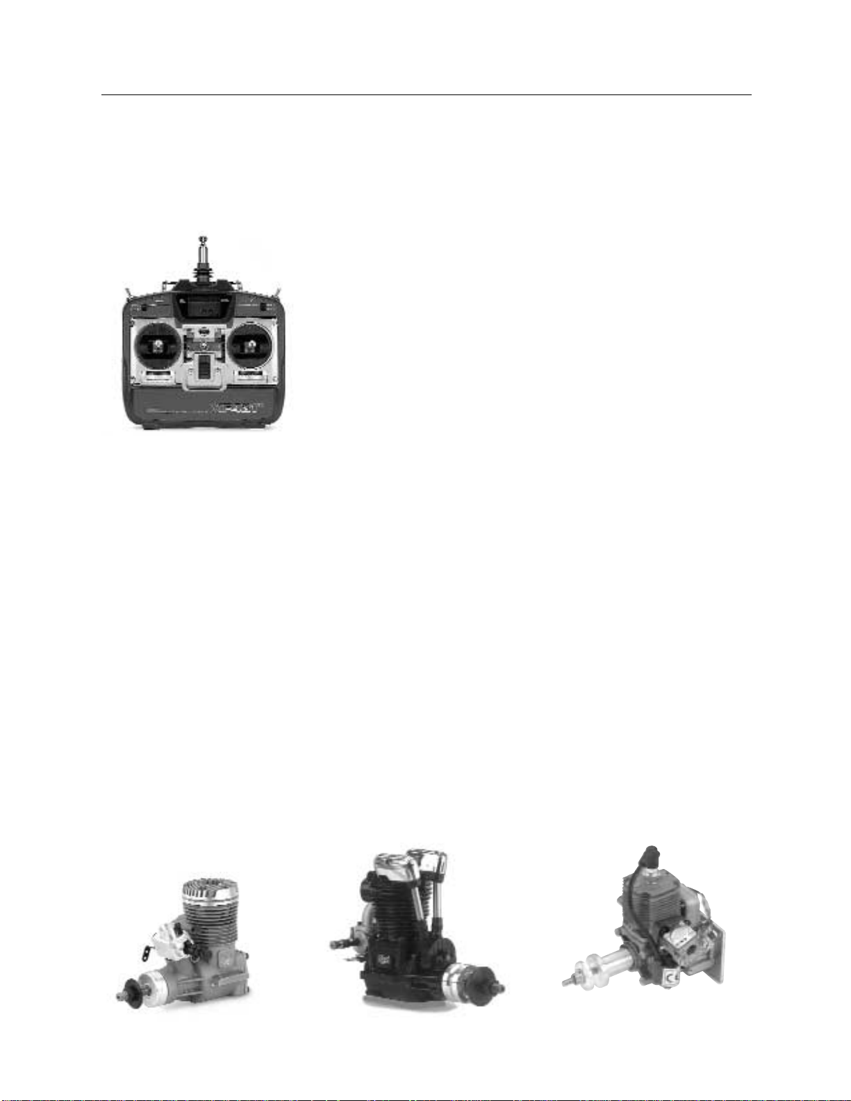
Additional Required Equipment . . . . . . . . . . . . . . . . . . . . . . . . . . . . . . . . . . . . . . . . . . . . . . . . . . . . . . . . . . . . . . . . . . . . . . . . . . .4
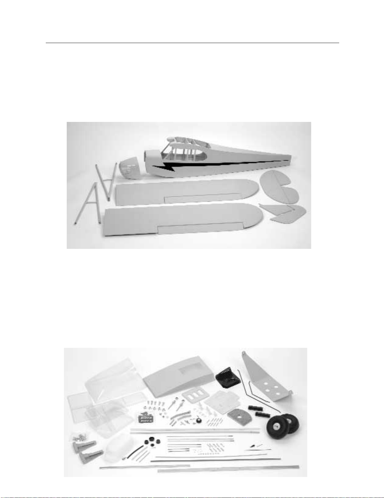
Kit Contents . . . . . . . . . . . . . . . . . . . . . . . . . . . . . . . . . . . . . . . . . . . . . . . . . . . . . . . . . . . . . . . . . . . . . . . . . . . . . . . . . . . . . . . . . .6
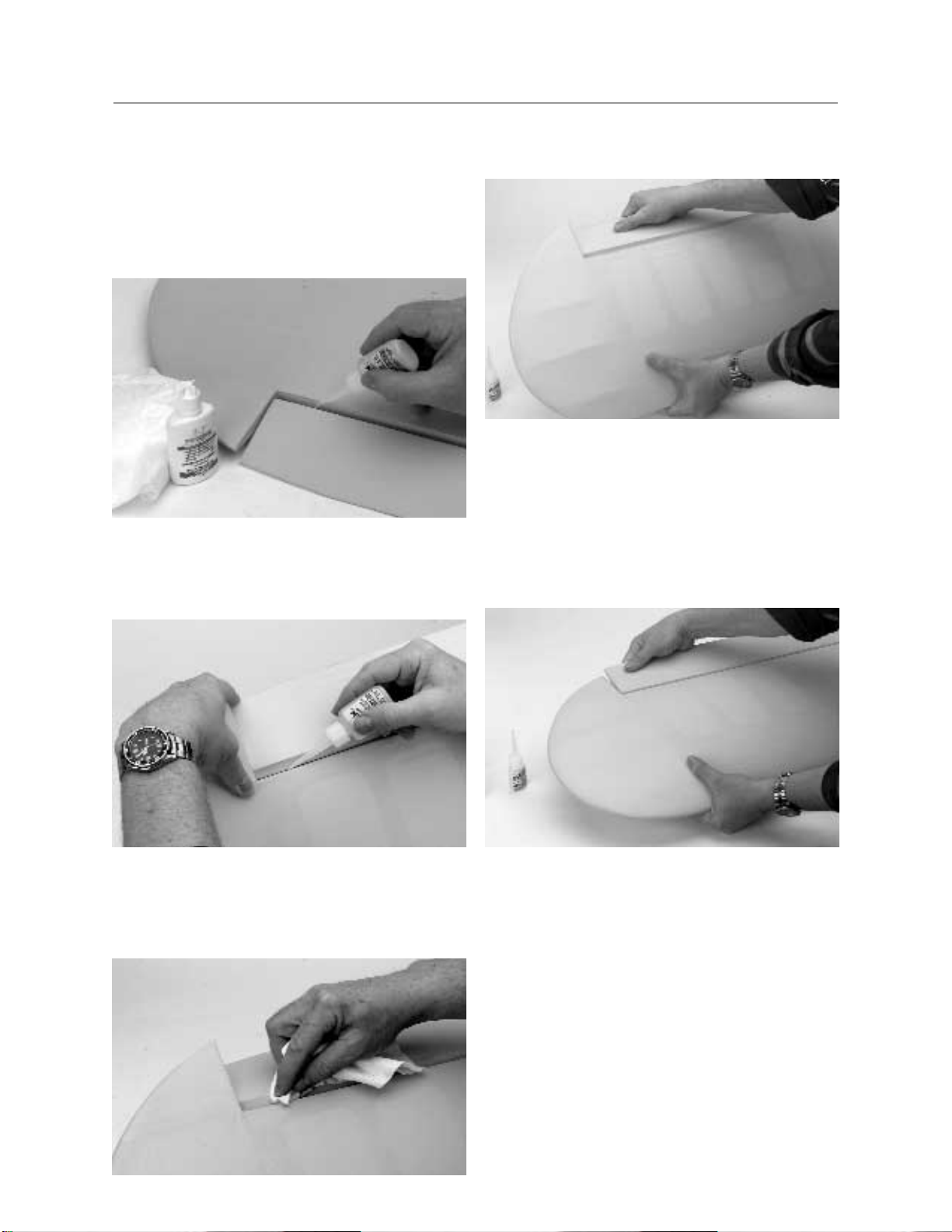
Section 1. Assembling the Wing . . . . . . . . . . . . . . . . . . . . . . . . . . . . . . . . . . . . . . . . . . . . . . . . . . . . . . . . . . . . . . . . . . . . . . . . . . .7
Section 2. Installing the Aileron Servos . . . . . . . . . . . . . . . . . . . . . . . . . . . . . . . . . . . . . . . . . . . . . . . . . . . . . . . . . . . . . . . . . . . . .9
Section 3. Installing the Aileron Linkages . . . . . . . . . . . . . . . . . . . . . . . . . . . . . . . . . . . . . . . . . . . . . . . . . . . . . . . . . . . . . . . . . . .12
Section 4. Bolting the Wing to the Fuselage . . . . . . . . . . . . . . . . . . . . . . . . . . . . . . . . . . . . . . . . . . . . . . . . . . . . . . . . . . . . . . . . .14
Section 5. Installing the Horizontal and Vertical Stabilizers . . . . . . . . . . . . . . . . . . . . . . . . . . . . . . . . . . . . . . . . . . . . . . . . . . . . . .15
Section 6. Installing the Rudder and Elevator Control Horns . . . . . . . . . . . . . . . . . . . . . . . . . . . . . . . . . . . . . . . . . . . . . . . . . . . . .19
Section 7. Mounting and Hinging the Elevators . . . . . . . . . . . . . . . . . . . . . . . . . . . . . . . . . . . . . . . . . . . . . . . . . . . . . . . . . . . . . . .21
Section 8. Hinging the Rudder and Mounting the Tail Wheel Assembly . . . . . . . . . . . . . . . . . . . . . . . . . . . . . . . . . . . . . . . . . . . . .22
Section 9. Installing the Main Landing Gear and Wheels . . . . . . . . . . . . . . . . . . . . . . . . . . . . . . . . . . . . . . . . . . . . . . . . . . . . . . . .24
Section 10. Installing the Engine (Glow) . . . . . . . . . . . . . . . . . . . . . . . . . . . . . . . . . . . . . . . . . . . . . . . . . . . . . . . . . . . . . . . . . . . .26
Section 11. Installing the Engine (Gasoline) . . . . . . . . . . . . . . . . . . . . . . . . . . . . . . . . . . . . . . . . . . . . . . . . . . . . . . . . . . . . . . . . .28
Section 12. Assembling and Installing the Fuel Tank (Glow and Gas Versions) . . . . . . . . . . . . . . . . . . . . . . . . . . . . . . . . . . . . . . . .30
Section 13. Installing the Radio System . . . . . . . . . . . . . . . . . . . . . . . . . . . . . . . . . . . . . . . . . . . . . . . . . . . . . . . . . . . . . . . . . . . .34
Section 14. Assembling and Installing the Rudder, Elevator and Throttle Linkages . . . . . . . . . . . . . . . . . . . . . . . . . . . . . . . . . . . . .37
Section 15. Installing the Wing Struts . . . . . . . . . . . . . . . . . . . . . . . . . . . . . . . . . . . . . . . . . . . . . . . . . . . . . . . . . . . . . . . . . . . . . .46
Section 16. Installing the Windshield ,Side Windows and Cabin Overhead Window . . . . . . . . . . . . . . . . . . . . . . . . . . . . . . . . . . . .48
Section 17. Attaching the Cowling . . . . . . . . . . . . . . . . . . . . . . . . . . . . . . . . . . . . . . . . . . . . . . . . . . . . . . . . . . . . . . . . . . . . . . . .50
Section 18. Control Throw Recommendations . . . . . . . . . . . . . . . . . . . . . . . . . . . . . . . . . . . . . . . . . . . . . . . . . . . . . . . . . . . . . . . .53
Section 19. Balancing the Hangar 9 1/4" Scale J-3 Cub . . . . . . . . . . . . . . . . . . . . . . . . . . . . . . . . . . . . . . . . . . . . . . . . . . . . . . . .54
Section 20. Detailing the J-3 Cub . . . . . . . . . . . . . . . . . . . . . . . . . . . . . . . . . . . . . . . . . . . . . . . . . . . . . . . . . . . . . . . . . . . . . . . . .55
Pre-Flight at the Field . . . . . . . . . . . . . . . . . . . . . . . . . . . . . . . . . . . . . . . . . . . . . . . . . . . . . . . . . . . . . . . . . . . . . . . . . . . . . . . . .59
AMA Safety Code . . . . . . . . . . . . . . . . . . . . . . . . . . . . . . . . . . . . . . . . . . . . . . . . . . . . . . . . . . . . . . . . . . . . . . . . . . . . . . . . . . . . .60
3-View Drawing of J-3 Cub . . . . . . . . . . . . . . . . . . . . . . . . . . . . . . . . . . . . . . . . . . . . . . . . . . . . . . . . . . . . . . . . . . . . . . . . . . . . .61
Templates for side and inverted mounting of 2-4 Cycle engines . . . . . . . . . . . . . . . . . . . . . . . . . . . . . . . . . . . . . . . . . . . . . . . . . . .63
Pushrod Exit template . . . . . . . . . . . . . . . . . . . . . . . . . . . . . . . . . . . . . . . . . . . . . . . . . . . . . . . . . . . . . . . . . . . . . . . . . . . . . . . . .65
Cowling templates . . . . . . . . . . . . . . . . . . . . . . . . . . . . . . . . . . . . . . . . . . . . . . . . . . . . . . . . . . . . . . . . . . . . . . . . . . . . . . . . . . . .66
Sky Window template . . . . . . . . . . . . . . . . . . . . . . . . . . . . . . . . . . . . . . . . . . . . . . . . . . . . . . . . . . . . . . . . . . . . . . . . . . . . . . . . . .68
Interior Floor templates . . . . . . . . . . . . . . . . . . . . . . . . . . . . . . . . . . . . . . . . . . . . . . . . . . . . . . . . . . . . . . . . . . . . . . . . . . . . . . . .70
Wing Letter/Number Size template . . . . . . . . . . . . . . . . . . . . . . . . . . . . . . . . . . . . . . . . . . . . . . . . . . . . . . . . . . . . . . . . . . . . . . . .73

3
Introduction
Thank you for your purchase of the Hangar 9 1/4 Scale Piper J-3 Cub. This kit will provide you with a scale model of the original
Piper J-3 Cub. We believe the design is perfect for R/C and makes a beautiful model that will be easy to fly.
Few would argue that the Piper “Cub” was one of the most popular light aircraft ever produced. Mass sales and acknowledged safety
made the “Cub” almost synonymous with American light aircraft.
The Full Scale J-3 Cub is powered by a Continental, Franklin or Lycoming 65 hp engine. Top speed is approximately 87 mph and
cruise is in the area of 73 mph. The J-3 Cub service ceiling is around 12,000 feet, with an approximate range of 220 miles at cruise.
The Piper J-3 Cub is 22' 4 1⁄2" long, has a 35' 2 1⁄2" wingspan, and measures 6' 6" in height. A military version, with some minor
changes, was designated the L-4 by the U.S. Army Air Corps. The L-4 saw service during World War II.
If you encounter difficulty in any construction sequence, please feel free to contact one of our technicians. We stand ready to provide
any assistance we can concerning the construction of your J-3 Cub. You can contact us at:
Horizon Hobby, Inc.
4105 Fieldstone Road
Champaign, IL 61822
(877) 504-0233
www.horizonhobby.com
Warning
An R/C aircraft is not a toy! If misused, it can cause serious bodily harm and damage to property. Fly only in open areas, preferably
AMA (Academy of Model Aeronautics) approved flying sites. Follow all instructions included with your radio and engine.

4
Additional Required Equipment
Radio Equipment
4 Channel minumum
5 Servos (JRPS531 or equivalent)
Standard 600-1100mAh receiver battery pack
"Y" Harness or servo extension
Recommended JR Systems
JR 400EX
JR 421 EX
JR XP652
JR XP783/388
JR XP8103
JR 10X
JR PCM10SX
Engine Requirements
1.08 - 1.48 2-cycle engines
1.20 - 1.80 4-cycle engines
23cc gasoline engine
Recommended Recommended Recommended
2-Cycle Engine 4-Cycle Engine Gasoline Engine
MDS 1.48 Saito 1.20 - 1.80 Zenoah G-23
Moki 1.35
WEBRA 1.20

5
Parts Needed (not included in the kit)
Aileron extension (2) (JRPA101, 18”, Gold)
Y harness (1)(JRPA133) (Needed to connect aileron servos to one channel (Aileron) of the receiver)
Propeller (Refer to propeller recommendations listed in your engine’s operating instructions)
Foam for cushioning tank
Fuel tubing (12")(Gas or glow, depending on your choice of engine)
Fuel filler
Shut-off switch for gasoline engine operation (ZEN20000)
Note: This is an important safety item for all gasoline powered engine installations.
Tools and Supplies Needed (not included in kit)
Adhesives
Thin CA (cyanoacrylate) glue
Thick CA (cyanoacrylate) glue
CA remover/debonder
6-minute Epoxy
30-minute Epoxy
Blue Locktite®
Canopy glue
Tools
Drill
Drill bits; 1/16", 1/8”, 5/32", 1/4", 3/8”
Medium Phillips screwdriver
Z-bend pliers
Pliers (needle nose)
Small round file
Hobby knife with #11 blade
Mixing sticks
Epoxy brushes
90-degree triangle
Medium sandpaper
Masking tape
Straight edge
Measuring device (e.g., ruler, tape measure)
Scissors
Paper towels
Wax paper
Rubbing alcohol
Felt-tipped pen/pencil
T-pins
Moto-tool with cut-off wheel
Other Equipment Items
Radio packing foam
Antenna tube
Scale detail supplies per Greg Hahn included in instructions

6
Kit Contents
Note: Photo of product may vary slightly from contents in the box.
Large Parts
Left wing panel with aileron (HAN1551) Wing struts (HAN1556)
Right wing panel with aileron (HAN1551) Fiberglass painted cowl (HAN1554)
Fuselage (HAN1553) Horizontal stabilizer and elevator (HAN1552)
Vertical stabilizer (fin) and rudder (HAN1552)
Small Parts
Windshield/Sidewindows (HAN1555)
Wing Joiner (HAN1559)
Landing gear (HAN1557)
Wheels (DUB425TLC)
Engine mount (glow) (HAN2033)
Servo Tray
Engine mount (Zenoah G-23)
Wood pushrods
4-40 pushrod linkages
Fuel Tank Floor
Landing Gear Support Wire &
Shock Absorbers (HAN1557)
Fuel tank w/gas option
(stopper/tubing)
Decals
Tail wheel and hardware (HAN1558)
Metal Clevis
Control horns
Control linkage hardware
Non-conductive Nylon Throttle
Pushrod (HAN1459)
Sky Window
Engine Valve Covers
Main axles

7
Section 1: Assembling the Wing
Note: The control surfaces, which include the ailerons, ele-
vator and rudder, come with the hinges installed, but
the hinges are not glued in place. It’s imperative that
you use a high-quality, thin CA glue to properly
adhere the hinges and control surfaces in place.
Step 1. The wing is made up of a left and right panel with the
ailerons temporarily mounted in place. You will glue them in
place in later steps in this section. Note that each aileron is con-
trolled by its own servo. You will need two servos when you
begin Section 2.
Step 2. Carefully remove one of the wing panels from its pro-
tective plastic. Remove the aileron from the wing panel. Note the
position of the hinges. The J-3 Cub comes with, four high-
quality hinges in each wing panel.
Step 3. Remove each hinge (4) from the wing panel and insert a
T-pin near the center of the hinge as shown below.
Step 4. Slide each hinge into the wing panel until the T-pin is
snug against the wing. This procedure is suggested to ensure
each hinge is positioned so an equal portion of the hinge is in
each (i.e., half in the wing and half in the aileron).
Step 5. Slide the aileron onto the wing until there’s only a slight
gap (1/32"). The hinge is now centered on the wing panel and
aileron. Remove the T-pins and snug the aileron against the wing
panel, so the aileron is free to move and does not bind.
• Right wing panel with aileron and hinges
• Left wing panel with aileron and hinges
• Instant thin CA glue
• CA remover/debonder
• Paper towels
• T-pins (one for each hinge)
Parts Needed Tools and Adhesives Needed

8
Step 6. Deflect the aileron and completely saturate each hinge
with thin CA glue. The aileron’s front surface should lightly con-
tact the wing during this procedure. Ideally, when the hinge is
glued in place, a 1/32" gap or less will be maintained throughout
the length of the aileron. The hinge is constructed of a special
material that allows the CA to wick (or penetrate) and distribute
throughout the hinge, securely bonding it to the wood structure.
Step 7. Turn the wing panel over and deflect the aileron in the
opposite direction from the opposite side. Apply thin CA glue to
each aileron hinge, making sure the CA penetrates into both the
aileron and wing.
Step 8. Use CA remover/debonder and a paper towel to remove
excess CA that may have accumulated on the wing or in the
aileron hinge area. Be careful when using debonder, as excess
and/or some brands might discolor the fabric.
Step 9. Flex the aileron back and forth to “work in” the hinges
and check for proper movement.
Step 10. Repeat this process with the other wing panel, secure-
ly hinging the aileron in place.
Step 11. After both ailerons are securely hinged and dry, firmly
grasp the wing and the aileron to check that the hinges are
securely glued and cannot be pulled apart. To do this, apply
medium pressure to try to separate the aileron from the wing.
Use caution to be certain you do not crush the wing structure.
CONTINUED
Section 1: Assembling the Wing

9
Section 2: Installing the Aileron Servos
Step 1. Locate the servo opening in the bottom of one of each
of the wing halves. Use a sharp knife to trim away the covering
over the openings. Use care not to cut away too much covering.
Step 2. Install the recommended servo hardware supplied with
your radio system onto the servos you will use for the Cub
(grommets and eyelets). Install a servo extension lead to each of
the aileron servos as well (an 18” extension is recommended).
Secure the connectors with either masking tape or a commercial-
ly available connector that prevents the servo lead connectors
from becoming disconnected.
Hint: It’s always a good idea to tape or secure the servo
connectors and servo extension together to prevent the
wires from becoming unplugged while inside the wing.
Step 3. Trial fit the wood servo blocks into the servo opening.
You will mount these with epoxy after you have made sure they
fit and that the servo will fit into the space.
Some material will have to be removed inside the servo opening to
make room for the servo lead at two locations. Make sure there is
room for the servo lead to go into the round hole made for it to pass
into the wing. Second, you will need to trim the area of the wood
servo block so the servo wire exiting from the servo case is not
crimped as it passes around or under the servo to the servo lead exit.
• Right/left wing panels
• Standard size servos with mounting hardware (2)
.Note: JRS 531 servos (or equivalent) are recommended.
• Servo extension (18”) (2)
• Wood servo blocks (4)
• Hobby knife with #11 blade • 6-minute epoxy
• Medium Phillips screwdriver • Rubbing alcohol
• Drill • Paper towels
• Drill bit: 1/16” • Epoxy brush
• Felt-tipped pen or pencil • Masking tape
• String (24”) with a small weight on end
Parts Needed Tools and Adhesives Needed

10
Step 4. Once you’re satisfied with the fit of the aileron servo in
the aileron servo bay, proceed to epoxy the wood servo mounts
into the aileron servo area. Mix up approximately 1/2 ounce of
6-minute epoxy, apply to the wood servo mounts and install into
the aileron servo bay. Allow the epoxy to cure before proceeding
with the next step.
Step 5. While the epoxy is curing, mount the servo arm onto
the servo after you have trimmed three of the arms off as shown.
Step 6. Once the epoxy has cured, you can begin to mount the
servo into the wing. You will want to first run the servo lead and
servo lead extension through the wing and out the wing root.
Step 7. We recommend using a piece (24") of the string (pro-
vided) with a nut from the hardware bag attached to one end.
Drop the nut through the opening in the wing root and let it slide
through the wing, exiting at the aileron servo bay area. Once you
have run the string through, you can remove the nut and tie the
string to one end of the servo extension lead. Fish the servo
leads back through the wing by pulling the string out. Secure the
servo lead with a piece of masking tape to prevent it from falling
back into the wing.
CONTINUED
Section 2: Installing the Aileron Servos

11
Step 8. Trial fit the servo into the aileron servo bay. You will
have to make sure the servo lead wire is not crimped. Note the
orientation of the servo and servo arm. The servo arm used to
control the aileron linkage is pointing to the wingtip. The servo
in the other wing half should be positioned so the servo arm
also points outward to the wing tip. Note also the servo is
mounted so the servo arm is positioned closer to the leading
edge of the wing.
Note: The supplied 4-40 threaded linkages are of a specified
length, so make sure the servos are orientated
correctly.
Step 9. With the servo in place, mark the location of the servo
screws, and then remove the servo.
Step10. Using a 1/16" drill bit, drill the servo screw locations
previously marked in Step 4. Once the pilot holes are drilled,
mount the servo using the screws provided in you radio system.
Step 11. Repeat the procedure for the other servo in the other
wing panel.
CONTINUED
Section 2: Installing the Aileron Servos

12
Section 3: Installing the Aileron Linkages
Step 1. Locate a 4/40 x 3 3/4" threaded rod, two 4-40 clevis,
two clevis locks and two nuts. You will also need a control horn,
plastic plate and two 2mm screws to mount the control horn to
the aileron control surface.
Step 2. Thread a 4-40 nut and clevis on each end of one of the
threaded rods.
Step 3. Before mounting the linkages, it’s a good idea to center
the wing servos electrically. Connect them to the receiver (if
using a “y” harness use the aileron channel only). Note: If you
are using separate channels for the ailerons, check to make sure
you connect to the appropriate channels (refer to radio operating
instructions for diagram).
Turn on your transmitter, then the receiver. Once the servos have
moved to their electrical center, you can position each aileron
servo arm so that it will be approximately 90 degrees to the link-
age when attached.
Next, turn off the receiver, then the transmitter.
Step 4. To establish the length of the linkage required, trial fit
the control horn and linkage to the servo arm. Adjustments to
length are made by screwing one or both clevis in or out. Be
sure to securely tighten the 4-40 nuts against the clevis to pre-
vent the clevis from backing out. The control horn should be
positioned so the holes that the clevis connects to are over the
centerline of the hinge line of the control surface.
Note: For normal applications, the clevis is connected to that
portion of the servo arm that points to the wing tip
(see below).
• Wing panels (right and left)
• Short (3-3/4") threaded rod (both ends) (2)
• Clevis (4)
• 4/40 nuts (4)
• Clevis locks (4)
• Control horn (1 for each wing panel)
• Plastic plate (2)
• 2mm screws (4)
• Medium Phillips screwdriver
• Drill
• Drill bit: 1/16"
• Felt-tipped pen or pencil
• Thin CA glue (optional)
Parts Needed Tools and Adhesives Needed

13
Step 5. Once you're satisfied with the control horn location
(remember, it should be a straight line from the servo arm to the
control horn), mark the location with a felt-tipped pen or pencil.
Note the linkage makes a 90-degree angle at the servo arm, and
at the center line of the hinge line of the aileron to wing.
Step 6. Using a 1/16" drill bit, drill the screw holes for mount-
ing the control horn. Since the aileron is balsa, we recommend
applying thin CA glue into the aileron through the drilled holes
to saturate and stiffen the balsa in the mounting area. Note: It
may be necessary to re-drill the holes after the CA has cured.
Step 7. Attach the control horn to the aileron using the screws
provided and a plastic plate. Be careful not to accidentally punc-
ture the covering with the Phillips screwdriver.
Step 8. Repeat the process for the remaining aileron.
CONTINUED
Section 3: Installing the Aileron Linkages

14
Section 4: Bolting the Wing to the Fuselage
Step 1. Locate the two aluminum wing braces, the wing brace
hardware, and the wing attachment bolts from the hardware bag.
Step 2. Attach the 24 1/2" long aluminum wing brace to the for-
ward portion of the cabin area using the hardware provided. You
may need to carefully trim the covering away from the opening.
The blind nuts are already installed. Use a drop of Threadlock
applied to the threads before installing the screws.
Step 3. Attach the 16" aluminum wing brace to the area behind
the forward brace using the screws provided. Remember to apply
Threadlock to the screws first.
Step 4. Slide both wing panels on the wing braces and attach
the left and right wing panels using the two wing bolts/washers
provided. This is a temporary installation to help in the align-
ment of the horizontal and vertical stabilizers in the next section.
Note: The wing struts will be installed in Section 15.
WARNING
The wing struts MUST be installed before flight. They
are functional, providing the support necessary for the
wing to withstand normal flight loads. Do not fly the
aircraft without the wing struts installed!
• Left and right wing panels
• Fuselage
• Aluminum wing brace 24 1/2" long
• Aluminum wing brace 16" long
• Aluminum wing brace screws (2 large w/washers and
2 small w/washers )
• Wing attachment bolts/washers (2 each)
• Allen wrench (provided in kit)
• Medium Phillips screwdriver
• Threadlock
Parts Needed Tools and Adhesives Needed

15
Section 5: Installing the Horizontal
and Vertical Stabilizer
Step 1. On the rear of the fuselage, slots are pre-cut in the
wood structure for the horizontal stabilizer and the vertical stabi-
lizer. Use a hobby knife to trim away the covering, using caution
to not cut into the balsawood.
Step 2. Remove the elevators from the horizontal stabilizer, tak-
ing care not to lose any of the CA hinges. The Elevators will be
attached in Section 7. Use a straightedge of locate the center line
of the horizontal stabilizer. This line will serve as a reference
point when the horizontal stabilizer is mounted to the fuselage.
Step 3. Slide the horizontal stabilizer carefully into the slot pro-
vided in the fuselage. You may have to trim the opening to allow
the horizontal stabilizer to be inserted. By noting the centerline
you marked, position the horizontal stabilizer so that it’s centered
in the fuselage opening where the vertical stabilizer will go.
Step 4. Mark the center of the rear of the fuselage (where the
rudder will be placed). Position the horizontal stabilizer so it’s
center line mark is in line with the fuselage rear mark. Use the
ruler to make sure the horizontal stabilizer projects an equal
amount on either side of the fuselage at that point (see below).
Also check that the stabilizer is level with the wing by sighting it
from the rear of the fuselage.
• Fuselage w/wing temporially mounted
• Horizontal stabilizer
• Vertical stabilizer
• Hobby knife with #11 blade
• Felt-tipped pen
• 30-minute epoxy
• Rubbing alcohol
• Masking tape
• 90-degree triangle
Parts Needed Tools and Adhesives Needed
• Ruler
• Pencil
• Paper towels
• Mixing stick
• Epoxy brush

16
Step 5. With the fuselage resting on a flat surface, align the
horizontal stabilizer by measuring from fixed points on the wing
to the outside of the trailing edge tip of the horizontal stabilizer.
Make sure the trailing edge of the horizontal stabilizer stays on
its center mark.
Step 6. Adjust the horizontal stabilizer until you have an equal
distance on both the right and left side of the fuselage and that
the horizontal stabilizer is positioned correctly (not tilted) with
reference to the wing. Refer to the illustration below.
Step 7. When you’re satisfied with the alignment of the horizon-
tal stabilizer with the wing, carefully mark the position with a
pencil at the junction where the horizontal stabilizer meets the
fuselage. The pencil should leave a slight indentation in the cov-
ering. Mark both the top and bottom of the horizontal stabilizer.
Step 8. Trial fit the vertical stabilizer in place on the fuselage,
after removing the rudder and hinges. Set these aside for now, as
the rudder will be attached later in Section 8. Make sure the ver-
tical stabilizer is inserted completely. Some trimming to the bot-
tom of the vertical stabilizer may be required.
Note: The back of the vertical stabilizer needs to be aligned
with the back of the fuselage.
Correct
Incorrect
CONTINUED
Section 5: Installing the Horizontal
and Vertical Stabilizer

17
Step 9. Carefully check the vertical stabilizer to make sure it’s
aligned 90 degrees to the horizontal stabilizer. A 90-degree
triangle is helpful in this step.
Hint: When installing the vertical stabilizer, use the rudder
to check for proper stabilizer height. It may be neces-
sary to cut off a small amount from the bottom of the
vertical stabilizer to get the rudder to drop down to the
proper position so the rudder and fuselage align.
Step 10. Double check the horizontal and vertical stabilizer
alignment. It may be necessary to slightly trim balsa wood on
the fuselage or tail parts with a sharp hobby knife to achieve
exact alignment.
Step 11. When you’re satisfied with the alignment, carefully
mark the position of the vertical stabilizer to fuselage with a pen-
cil at the junction where the vertical stabilizer meets the fuselage.
The pencil should make a light indentation in the covering.
Step 12. Remove the horizontal and vertical stabilizers from the
fuselage. Using a sharp hobby knife and a straight edge, careful-
ly cut the covering at approximately 1/16" inside the lines you
drew, on both sides of the horizontal and vertical stabilizer
Note: Some covering may already be removed. If necessary,
remove any excess.
CAUTION
It is very important that you do Not press hard enough
to cut into the wood structure, as doing so could weak-
en the horizontal stabilizer.
CONTINUED
Section 5: Installing the Horizontal
and Vertical Stabilizer

18
Step 13. Mix up approximately 1/2 ounce (minimum) of
30-minute epoxy to attach the horizontal stabilizer to the fuse-
lage. Slide the horizontal stabilizer back into the fuselage. Epoxy
will have to be worked into the fuselage opening by sliding the
horizontal stabilizer back and forth (approximately 1/8"-1/4") and
applying epoxy to the top and bottom surfaces. Use an epoxy
brush to apply the epoxy. Some can be inserted through the top
vertical stabilizer slot, but use care not to overdo, as the vertical
stabilizer will have to be installed also.
Step 14. Check the alignment of the horizontal stabilizer by
referring to the marks made previously, and measuring the wing
to horizontal stabilizer as done in Step 5 and Step 6. Clean
excess epoxy away from the horizontal stabilizer/fuselage junc-
tion with rubbing alcohol and a paper towel. Use masking tape to
hold the horizontal stabilizer in place while epoxying the vertical
stabilizer in place in the next step.
Step 15. Mix up 1/2 ounce of 30-minute epoxy and apply to
the vertical stabilizer where the fuselage contacts it. Also, apply
epoxy to the base of the vertical stabilizer where it mounts to the
fuselage and horizontal stabilizer. Insert the vertical stabilizer into
the fuselage and wipe away any excess epoxy with a paper towel
and rubbing alcohol.
Step 16. Check the alignment of the vertical stabilizer to the
horizontal stabilizer and wing by sighting from the rear of the air-
craft. Use masking tape to hold the vertical stabilizer in place
while the epoxy cures. Allow the epoxy to cure completely.
Step 17. The right and left wing panels may be removed at this
time to ease the construction process.
CONTINUED
Section 5: Installing the Horizontal
and Vertical Stabilizer
Correct

19
Section 6: Installing the Elevator
and Rudder Control Horns
Step 1. Locate the two elevator halves. Make sure the hinges
are still installed. You will also need two nylon control horns,
two backplates and four screws.
Step 2. For illustration purposes, we will describe installing the
control horn on the bottom of the right elevator first. Measure
1/2" back from the hinge line of the elevator and 1/2" from the
edge of the elevator that is closest to the fuselage. Make a mark
with a felt-tipped pen. Do the same for the other elevator.
Step 3. Locate one nylon horn. Trial fit the horn on the right
elevator with the horn positioned so the holes that the clevis will
go into are aligned with the hinge line of the elevator (the for-
ward edge that will fit against the horizontal stabilizer).
Step 4. Line up the inside edge of the horn with the mark you
made in Step 2. Mark the screw holes with a felt-tipped pen
or pencil.
• Control horns (3)
• Control horn back plates (3)
• Control horn screws (12)
• Fuselage with horizontal and vertical stabilizers attached
• Elevators (2)
• Rudder
• Thin CA glue
• CA debonder
• Drill
• Drill bit: 1/16", 3/32"
• Felt-tipped pen/pencil
• Medium Phillips screwdriver
• Ruler
Parts Needed Tools and Adhesives Needed

20
Step 5. Using a 1/16" drill bit, drill two pilot holes for the horn.
After the holes are drilled, you will want to put a drop of CA glue
in each hole to help strengthen the balsa. You will have to re-
drill the holes after the CA has cured.
Step 6. Mount the control horn using the two screws. Carefully
screw in the screws and engage the plastic plate on the other
side. We recommend covering the area around the horn with
masking tape to prevent damage to the covering in case the
screwdriver slips.
Step 7. Repeat the process in Steps 2–6 for the left elevator.
Once the control horns are mounted on the elevators, they can
be removed while the rudder control horn is being installed. The
elevators will be permanently hinged later.
Step 8. Locate the remaining control horn and associated hard-
ware. The top of the rudder control horn is located 1 5
–
8"up from
the bottom of the rudder. Measure and mark the left side of the
rudder (as the pilot is sitting in the cockpit). This is the side the
rudder linkage will be attached.
Step 9. Trial fit the rudder control horn centered on your mark
and make sure the portion of the horn with the holes is centered
over the hinge line of the rudder. If not, adjust as necessary. It's
important the rudder control horn be centered on the hinge line
of the vertical stabilizer/rudder.
Step 10. When you're satisfied, mark the two screw holes with
a felt-tipped pen or pencil. The horn location should not interfere
with the movement of the elevators up or down.
Step 11. Drill the holes using the same procedure in Step 5.
Use caution when drilling so the covering is not damaged.
Step 12. Carefully mount the rudder control horn using the
same method as previously described.
CONTINUED
Section 6: Installing the Elevator
and Rudder Control Horns
Other manuals for J-3 Piper Cub
1
Table of contents
Other Hangar 9 Aircraft manuals
Popular Aircraft manuals by other brands

RRD
RRD 2006 kite user manual

Piper
Piper TOMAHAWK Pilot's operating handbook and faa approved airplane flight manual

Shark
Shark UL Flight manual

Tuff Birds
Tuff Birds Micro BEE Instructional manual

Europa Aircraft
Europa Aircraft XS Monowheel Motorglider owner's manual

Aerola
Aerola Alatus-M Series Assembling and dismantling manual