Seagull Models CASSUTT 3M RACER User manual

1
“Graphics and specifications may change w ithout notice”.
ASSEMBLY MANUAL
MS: 164
Specications:
Wing span ---------------------------- 65in (165cm)
Wing area ---------------1038.5sq.in (67.0sq dm)
Weight -------------------------------16.8lbs (7.6kg)
Length -----------------------------70.8in (179.8cm)
Engine ------------------- F1 Air race 60cc engine
Radio ---------- 6 channels with 6 digital servos

CASSUTT 3M RACER Instruction Manual.
2
ank you for choosing the CASSUTT 3M RACER ARTF by SG MODELS. e CAS-
SUTT 3M RACER was designed with the intermediate/advanced sport yer in mind. It is a
semi scale airplane which is easy to y and quick to assemble. e airframe is convention-
ally built using balsa, plywood to make it stronger than the average ARTF, yet the design
allows the aeroplane to be kept light. You will nd that most of the work has been done for
you already. e motor mount has been tted and the hinges are pre-installed. Flying the
CASSUTT 3M RACER is simply a joy.
is instruction manual is designed to help you build a great ying aeroplane. Please read
this manual throughly before starting assembly of your CASSUTT 3M RACER Use the
parts listing below to indentify all parts.
If you are inexperienced with basic R/C ight we strongly recommend you contact your
R/C supplier and join your local R/C model Flying Club. R/C Model Flying Clubs oer a
variety of training procedures designed to help the new pilot on his way to successful R/C
ight. ey will also be able to advise on any insurance and safety regulations that may
apply.
Please be aware that this aeroplane is not a toy and if assembled or used incorrectly it is
capable of causing injury to people or property. WHEN YOU FLY THIS AEROPLANE
YOU ASSUME ALL RISK & REPONSIBILITY.
INTRODUCTION
WARNING
KIT CONTENTS
1
33
2
2
6
45
7
8
9
10
11
7
8

3
INSTALL THE AILERONS
1.
2.
3.
Epoxy
Use a small piece of rough sandpaper to
scu the hinges for better epoxy adhesion.
Do this to all aileron hinges.
Remove the ailerons from the wing and
remove the hinges.
Apply epoxy to each hinge where it will
be inserted into the ailerons. Tip: Apply
some petroleum jelly to the metal pin
hinge area to keep epoxy from interfering
with smooth operation of hinge.
Please see pictures below.
KIT CONTENTS
SEA164 CASSUTT 3M RACER
1. Fuselage
2. Wing set (2)
3. Tail set (2)
4. Cowling
5. Canopy
6 Wing Tube
7. Main landing gear
8. Tailwheel
9. Fiberglass wheel pants
10. Wheels
11. Pilot
12. Hardware bag included
ADDITIONAL ITEMS REQUIRED
TOOLS & SUPPLIES NEEDED
in cyanoacrylate glue.
Medium cyanoacrylate glue.
30 minute epoxy.
5 minute epoxy.
Hand or electric drill.
Assorted drill bits.
Modelling knife.
Straight edge ruler.
2mm ball driver.
Phillips head screwdriver.
220 grit sandpaper.
90° square or builder’s triangle.
Wire cutters.
Masking tape & T-pins.
read-lock.
Paper towels.
�F1 Air race 60cc engine
�Computer radio 6 channel with 6
servos.
�Glow plug to suit engine.
�Propeller to suit engine.
�Protective foam rubber for radio
system.

CASSUTT 3M RACER Instruction Manual.
4
INSTALL THE AILERONS
CONTROL HORN
Fiberglass control horn
1.
5.
7.
6.
8.
4.
Insert all four hinges in the ailerons at
this time. Make sure hinges move up and
down in right direction and not side to
side !
Be sure to test the aileron hinges once
you insert them. Ensure that the hinge
pockets line up, and that the hinges move
freely before the epoxy dries.
Check the t of the aileron to the wing.
e top of the ailerons will align to the
top of the wing. Make sure movement is
smooth and bind free.
We prefer 30-minute epoxy to allow
enough working time during the hinge
installation.
Apply epoxy into each of the holes in the
ailerons using a spare piece of pushrod
wire or toothpick.
Make sure to use enough epoxy so it
securely adheres the hinge to the surfaces.
Do not use an excessive amount of epoxy
when gluing the hinges so that it expels
from the hinge area.
Epoxy
Epoxy

5
Ailerons control horn
Epoxy
Epoxy
2.6.
3.
4.
5.
INSTALLING THE AILERON SERVOS
1.
Because the size of servos dier, you
may need to adjust the size of the precut
opening in the mount. e notch in the
sides of the mount allow the servo lead to
pass through.
Place the servo between the mounting
blocks and space it from the hatch. Use a
pencil to mark the mounting hole loca-
tions on the blocks.
Minimum servo spec.
Torque : 6.0V: 192.4 oz-in (13.8 kg-cm)
7.4V: 350.0 oz-in (25.2 kg-cm)

CASSUTT 3M RACER Instruction Manual.
6
Use dental oss or heat shrink tubing
to secure the connection between the
servo and extension wire so they cannot
become unplugged accidentally.
C/A glue
4.
5.
Use drill bit in a pin vise to drill the
mouting holes in the blocks.
Apply 2-3 drops of thin C/A to each of
the mounting holes. Allow the C/A to
cure without using accelerator.
1.5mm
2.
3.
Secure the servo to the aileron hatch
using a proper driver and the screws
provided with the servo.
Apply 2-3 drops of thin C/A to each of
the mounting aileron hatch mounting
tabs in the wing. ***Allow the C/A to cure
without using accelerator.***
Remove the string from the wing at the
servo location and use the tape to attach it
to the servo extension lead. Pull the lead
through the wing and remove the string.
6.
7.
C/A glue

7
8 .
9.
10.
Set the aileron hatch in place and use a
Phillips screw driver to install it with four
wood screws.
3x10mm
11.
AILERON PUSHROD HORN
INSTALLATION
Required Parts
• Wing assembly(le and right)
• 2.6mmx50mm threaded rod(2)
• 3mm metal clevis with silicone tub-
ing(4)
• Lock nut(4)
Required Tools and Adhesives
• Phillips screwdrive
• 30-mminute epoxy
12.
1.
2.
3.
55mm
70mm

CASSUTT 3M RACER Instruction Manual.
8
WHEEL AND WHEEL PANTS
INSTALLATION
Required Parts
• Fuselage assembly
• Landing gear (2)
• Washer (2)
• Axle (2)
• Plywood washer (2)
• Wheel collar (4)
• Wheel pant(right and le)
• Wheel(2)
Required Tools and Adhesives
• Drill
• Drill bits:4mm
• Phillips screwdrive (large).
Locate the items neccessary to install
the wheel and wheel pants to the landing
gear as shown.
You have to trim each axle using a tool
cutting and cut-o wheel.
Slide the collar to the axle and setscrew
the collars to secure the collar to the axle
and then slider the wheel on the axle with
a drop of oil on the axle so the wheel will
spin freely when installed. Prepare a sec-
ond collar and tighten the setscrew us-
ing hex wrench to secure the collar to the
axle.
Place the wheel assembly in the wheel
pants. e threaded portion of the axle
will t the notch of the wheel pant as
shown.
Caution when cutting the axles and
wear protective goggles.
4.
1.
2.
3.
4.

9
Slide the threaded end of the axle
through the hole in the bottom of the
landing gear leg. Use a washer and lock-
nut to tighten the axle to the landing gear.
Make sure to use threadlock on the nut so
it won’t vibrate loose in ight as shown.
Tighten the setcrews using a hex wrench
to secure the collars on the axle over the
at spot to retain the wheel as shown.
5.
6.
7.
Repeat steps as above to attach remain-
ing wheel pants to the landing gear.
8.
9.
10.
11.
CASSUTT 3M RACER Instruction Manual.
10
.
INSTALLING THE FUSELAGE SERVOS
.
Because the size of servos dier, you
may need to adjust the size of the precut
opening in the mount. e notch in the
sides of the mount allow the servo lead to
pass through.
Install the rubber grommets and brass
collets into all servos. Test t the servos
into the fuselage servo mounts.
Required Parts
• Fuselage assembly
Required Tools and Adhesives
• Drill
• Drill bits:2mm
• Phillips screwdrive (small)
Secure the servos with the screws
provided with your radio system.
1.
3.
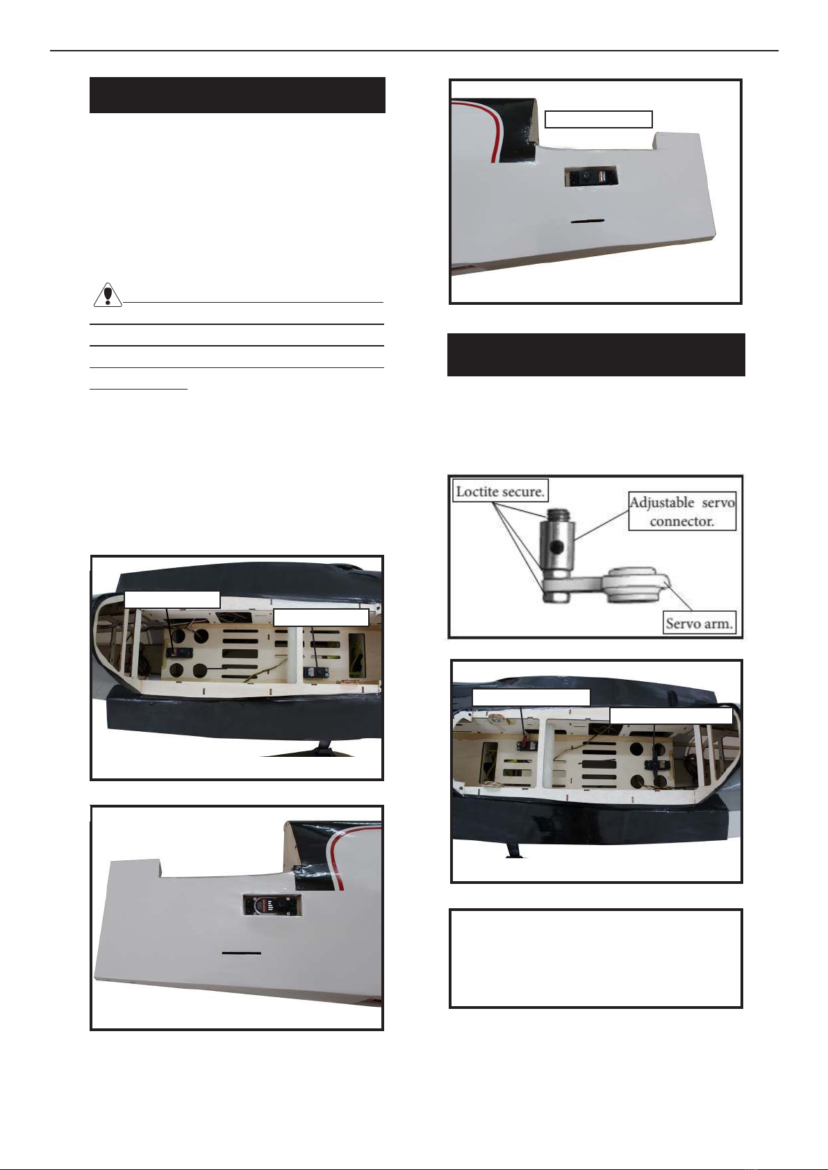
THROTTLE SERVO ARM
INSTALLATION
Install adjustable servo connector in the
servo arm as same as picture below:
2.
Rudder servo arm
Elevator servo
1.
rottle servo
rottle servo arm
2.
Minimum servo spec.
Torque : 6.0V: 192.4 oz-in (13.8 kg-cm)
7.4V: 350.0 oz-in (25.2 kg-cm)
Rudder servo

11
3.
4.
2.
Elevator servo arm
INSTALLING THE SWITCH
Install the switch into the precut hole in
the side, in the fuselage.
3/32” Hole
1.
Trim and cut
3.
4.
5.
Trim and cut
Switch
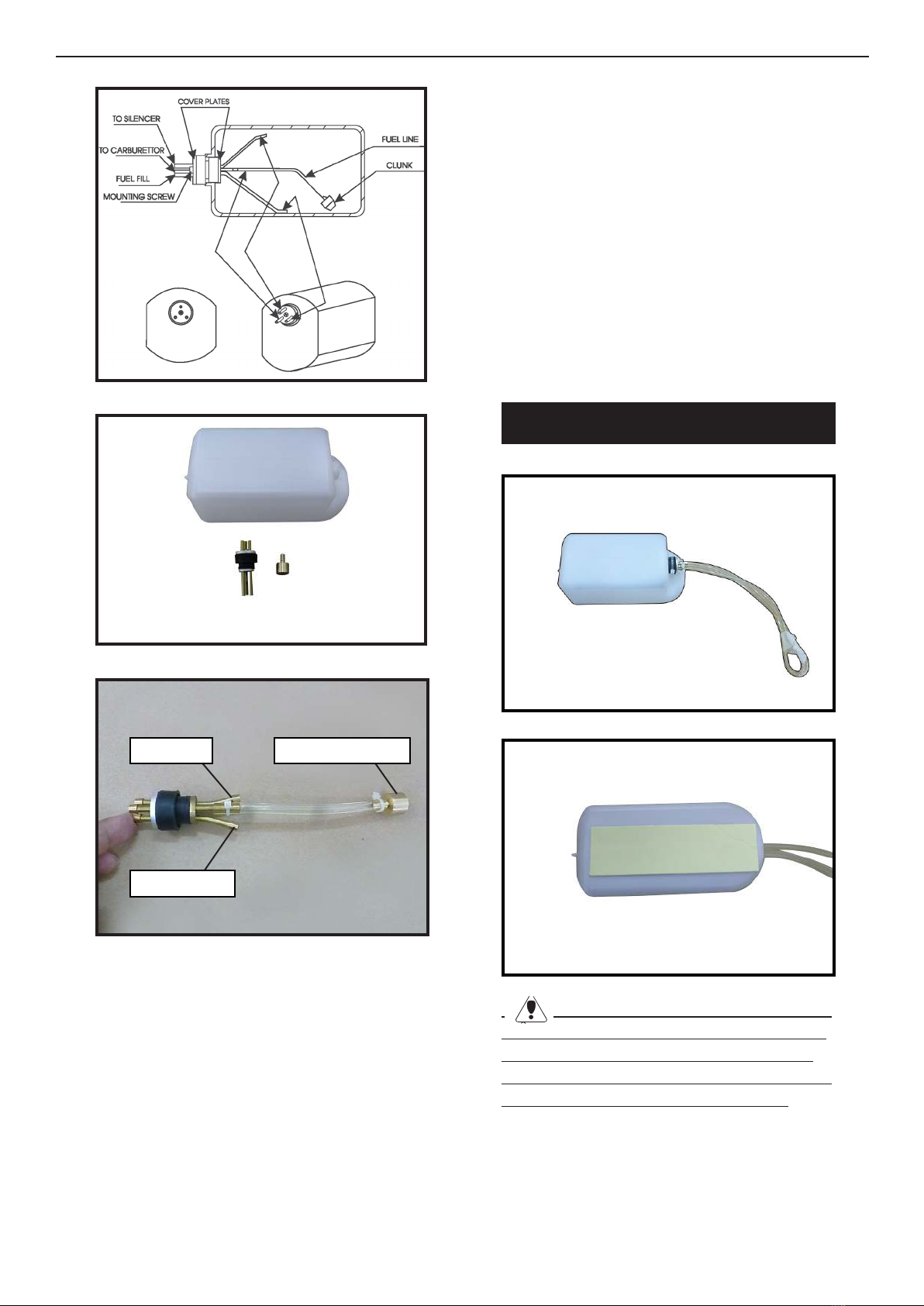
INSTALLING THE STOPPER
ASSEMBLY
Using a modeling knife, carefully cut
o the rear portion of one of the 3 nylon
tubes leaving 1/2” protruding from the
rear of the stopper. is will be the fuel
pick up tube.
Using a modeling knife, cut one length
of silicon fuel line. Connect one end of
the line to the weighted fuel pick up and
the other end to the nylon pick up tube.
Switch
CASSUTT 3M RACER Instruction Manual.
12
1.
2.
Carefully bend the second nylon tube up at
a 45º angle. is tube is the vent tube.
3.
Test t the stopper assembly into the tank.
It may be necessary to remove some of the
ashing around the tank opening using a
modeling knife. If ashing is present, make
sure none falls into the tank.
FUEL TANK INSTALLATION
When satised with the alignment of the
stopper assembly tighten the 3x20mm ma-
chine screw until the rubber stopper expands
and seals the tank opening. Do not overtight-
en the assembly as this could cause the tank
to split.
With the stopper assembly in place, the
weighted pick-up should rest away from the
rear of the tank and move freely inside the
tank. e top of the vent tube should rest just
below the top of the tank. It should not touch
the top of the tank.
1.
2.
Fuel pick up tubeVent tube
Fuel lltube
Slide the fuel tank into the fuselage. Guide
the lines from the tank through the hole in
the ewall.
You should mark which tube is the vent
and which is the fuel pickup when you attach
fuel tubing to the tubes in the stopper. Once
the tank is installed inside the fuselage, it may
be dicult to determine which is which.

13
3.
4.
.
5.
Use a 1/4 bit to drill the engine mounting
holes. Remove mounting template from fie
wall. Firewall shown with mounting holes
drilled ready for engine mounting.
Using mounting bolts and washers mount
engine to fiewall.
8.
9.
6.
7.
51mm

CASSUTT 3M RACER Instruction Manual.
14
Drill a hole for the throttle pushrod.
Connect the lines from the tank to the en
gine and muer. e vent line will connect to
the muer and the line from the clunk to
the carburetor.
10.
Blow through one of the lines to ensure
the fuel lines have not become kinked inside
the fuel tank compartment. Air should ow
through easily.
MOUNTING THE ENGINE
Please see below pictures.
1.
2.
3.
4.
5.
6x90mm

15
6.
7.
8.
170mm
9.
10.
13.
11.
12.
Ignition Modude

CASSUTT 3M RACER Instruction Manual.
16
14.
COWLING
- Please see below pictures.
3.
1.
2.
Tape the cowl to the fuselage using low-
tack tape.
4.
5.
6.
Use a drill and drill bit to drill the holes
for the cowl mounting screws. Make sure
the cowl position is correct before drill-
ing each hole.

17
With the muer, needle valve, and spark/
glow plug removed from the engine, slide
the cowl in place over the engine. Tem-
porarily install the propeller and spinner
in order to d the exact location of the
cowl. When satised with the cowl place-
ment, secure the cowl to the fuselage us-
ing masking tape.
Install the muer and muer extension
onto the engine and make the cutout in
the cowl for muer clearance. Connect
the fuel and pressure lines to the carbu-
retor, muer and fuel ler valve. Secure
the cowl to fuselage using the M3x10mm
socket head screws. Putting a small length
of silicon fuel tube under the head of the
screw helps with vibration.
7.
8.
M3x10mm
Loctite
9.
Because of the size of the cowl, it may be nec-
essary to use a needle valve extension for the
high speed needle valve. Make this out of suf-
cient length 1.5mm wire and install it into
the end of the needle valve. Secure the wire in
place by tightening the set screw in the side of
the needle valve.
10.
11.

CASSUTT 3M RACER Instruction Manual.
18
14.
12.
13.
15.
INSTALLING THE SPINNER
- Install the spinner backplate, propeller
and spinner cone.
1.
e propeller should not touch any
part of the spinner cone. If it does, use a
sharp modeling knife and carefully trim
away the spinner cone where the propel-
ler comes in contact with it.
M3x10mm
2.
Test t the hinges into the elevator, and
then the hinges into the tail. Ensure that
the hinge pockets line up, and that the
hinges move freely.
INSTALL NAIL HINGE ELEVATOR

19
1.
Epoxy.
2.
3.
4.
3.
Install the elevator control horn using
the same method as same as the elevator
control horns.
INSTALL ELEVATOR CONTROL HORN
4.
2.
1.

CASSUTT 3M RACER Instruction Manual.
20
5.
4.
1.
2.
3.
HINGING THE RUDDER
Glue the top three rudder hinges in
place using the same techniques used to
hinge the elevator.
e lower hinge will be glued when the
n/rudder assembly is attached to the fu-
selage.
Epoxy
5.
6.
Other Seagull Models Aircraft manuals


