Hansford sensors HS-510 User manual

HS510 USER GUIDE
QM015 Issue 1
Page 1
HS-510 DUAL TRIP AMPLIFIER
WITH ISOLATED
RE-TRANSMITTED OUTPUT
680 1957 F E W

HS510 USER GUIDE
QM015 Issue 1

CONTENTS
1. OVERVIEW ------------------------------------------------------------------------------------- 4
1.1 Product Identification ---------------------------------------------------------------------- 4
1.2 Standard HS-510 Modules----------------------------------------------------------------- 5
2. HS-510 FUNCTIONS-------------------------------------------------------------------------- 5
2.1 Display --------------------------------------------------------------------------------------- 5
2.2 Relays & LEDs------------------------------------------------------------------------------ 5
2.3 Alarm Level Settings ----------------------------------------------------------------------- 6
2.4 Alarm Delays -------------------------------------------------------------------------------- 6
2.5 Relay Latching ------------------------------------------------------------------------------ 6
2.6 Re-Transmitted Output--------------------------------------------------------------------- 6
3. INSTALLATION NOTES--------------------------------------------------------------------- 6
3.1 General --------------------------------------------------------------------------------------- 6
3.2 Signal Pick-up ------------------------------------------------------------------------------- 7
3.3 Ground Loops ------------------------------------------------------------------------------- 7
4. CONNECTION DETAILS -------------------------------------------------------------------- 7
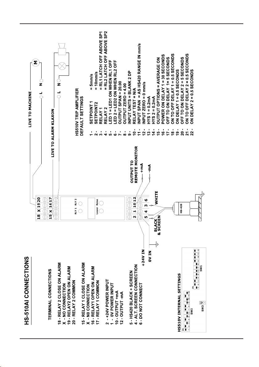
HS-510AI Connections -------------------------------------------------------------------- 8
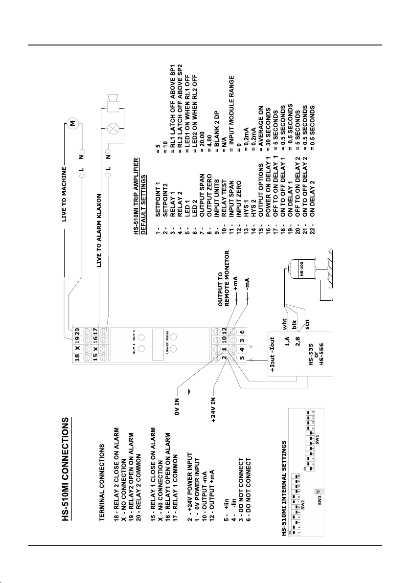
HS-510MI Connections -------------------------------------------------------------------- 9
HS-510MV Connections------------------------------------------------------------------- 10
HS-510TL + HS-420T Connections------------------------------------------------------ 11
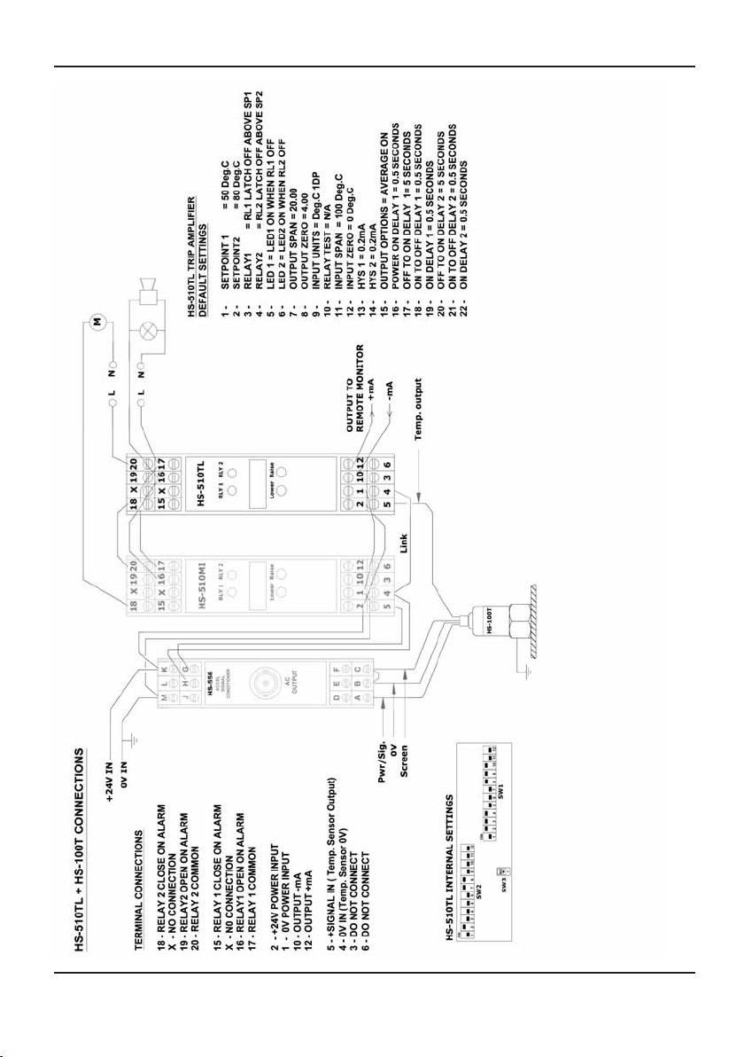
HS-510TL + HS-100T Connections------------------------------------------------------ 12
HS-510TS Connections -------------------------------------------------------------------- 13
5. RE-CONFIGURING HS-510 FUNCTIONS ---------------------------------------------- 14
5.1 Set Point Menu ------------------------------------------------------------------------------ 14
5.2 Main Menu----------------------------------------------------------------------------------- 14
5.3 Menu 3 & 4 – Relay 1 & Relay 2--------------------------------------------------------- 15
5.4 Menu 5 & 6 – LED 1 & LED 2 ------------------------------------------------------------16
5.5 Menu 7 & 8 – Output Span & Output Zero ----------------------------------------------16
5.6 Menu 9 – Input Units------------------------------------------------------------------------17
5.7 Menu 10 – Relay Test -----------------------------------------------------------------------17
5.8 Menu 11 & 12 - Input Span & Input Zero ------------------------------------------------17
5.9 Menu 13 & 14 - HYS1 & HYS2-----------------------------------------------------------17
5.10 Menu 15 – Output Options----------------------------------------------------------------17
5.11 Menu 16 – Power On Delay --------------------------------------------------------------18
5.12 Menu 17 & 20 – Off to On Delays 1 & 2 -----------------------------------------------18
5.13 Menu 18 & 21 – On to Off Delays 1 & 2 -----------------------------------------------19
5.14 Menu 19 & 22 – On Delays 1 & 2 -------------------------------------------------------19
6. RE-CONFIGURING THE HS-510 OUTPUT AND INPUTS ---------------------------20
6.1 Set the Re-Transmitted Output-------------------------------------------------------------21
6.2 Set Voltage Input ----------------------------------------------------------------------------22
6.3 Set Current Input---------------------------------------------------------------------------- 23
6.4 HS-510 Error Messages---------------------------------------------------------------------24
7. HS-510 SPECIFICATIONS @ 25°C -------------------------------------------------------24
8. WARRANTY -------------------------------------------------------------------------------------25
HS510 USER GUIDE
QM015 Issue 1
3

1. OVERVIEW
The HS-510 series Dual Trip Amplifiers are versatile and highly configurable DIN rail mounting
modules designed to provide fail-safe vibration or temperature monitoring and indication. A
digital display, two alarm relays and an isolated, re-transmitted output for remote monitoring are
provided. HS-510 module configuration and calibration is carried out at the factory to a level of
accuracy exceeding the normal requirements of vibration monitoring systems. The modules
operate from a 24Vdc or ac supply and are available in a number of standard configurations.
Connections to the module are made via numbered screw terminals and connection details and
default settings are shown in the following pages. For non-standard applications, full re-
configuring information and specifications are also included.
1.1 Product Identification
The HS-510 modules are identified by a 14 digit code which defines the input, output, display
and relay functions as shown below.
HS510 USER GUIDE
QM015 Issue 1 4

1.2 Standard HS-510 Modules
Several standard configurations are available as follows:-
HS-510AI - For vibration monitoring using a directly connected HS-420 series 4-20mA
sensor. The sensor is loop-powered from an isolated supply in the module.
Connection details and default settings are shown on page 8.
HS-510MI - For vibration monitoring using an HS-100 series constant current type
sensor and a signal conditioning module such as an HS-535 or HS-556
having a 4-20mA output. Connection details and default settings are shown
on page 9.
HS-510MV - For vibration monitoring using an HS-100 series constant current type
sensor and a signal conditioning module such as an HS-530 having a 0-10V
output. Connection details and default settings are shown on page 10.
HS-510TL - For temperature monitoring using a 10mV/°C temperature sensor as fitted
in the HS-100T and HS-420T series accelerometers. Connection details and
default settings for both sensors are shown on pages 11 and 12.
HS-510TS - For temperature monitoring using Pt100 resistive temperature sensor.
Connection details and default settings are shown on page 13.
2. HS-510 FUNCTIONS
Many of the HS-510 functions are software controlled using the display and the ‘Raise’ and
‘Lower’ buttons on the front panel of the module. The control menus are at two levels. Level 1 is
accessed by depressing both buttons for 2 seconds, and allows adjustment of the alarm levels only,
as described in section 2.3. Level 2, the main menu, is accessed by a sequence of button presses as
in section 5.2. Input and output functions are set by internal switches as described in section 6.
2.1 Display
The HS-510 display is set to indicate the range of the sensor used eg. 0-25mm/s, 0-2g, 0-
100°C, using the main menu functions 11. INPUT SPAN and 12. INPUT ZERO
2.2 Relays & LEDs
Alarm relays are set to be powered-on in the non-alarm condition for fail-safe operation.
Lit LEDs will indicate an alarm condition. Main menu functions 3. RELAY 1 and 4.
RELAY 2 and 5. LED 1 and 6. LED 2 are used to set these.
HS510 USER GUIDE
QM015 Issue 1
5

Page 5
2.3 Alarm Level Setting
The alarm level for RL1 (SP1) has been set nominally at 5 and for RL2 (SP2) at 10. The
alarm levels can be easily changed on installation by using the front panel ‘raise’ and
‘lower’ buttons as follows:-
(a) Depress and hold both ‘raise’ and ‘lower’ buttons together for at least 2
seconds until ‘OK’ is displayed.
(b) Select ‘1.SETPOINT1’ or ‘2.SETPOINT2’ on the display using either button.
(c) Press and release both buttons quickly to display the current setting.
(d) Adjust the setting using the ‘raise’ or ‘lower’ button.
(e) Depress and release both buttons quickly to return to the SETPOINT menu.
(f) Depress and hold both buttons for at least 2 seconds until ‘OK’ is displayed to
return to the run mode.
For changes to all other HS-510 settings it is necessary to enter the Main Menu using a
sequence of button presses. Refer to section 5.2 for details.
2.4 Alarm Delays
To allow for excess vibration on start-up, a power on delay is set to 30 seconds, during
which no alarms will operate. In addition both alarms are set with a 5 second delay such
that the alarm conditions must be present for at least this time before the alarms operate.
These are set using the Main Menu functions 16 to 22 as described in sections 5.11 to 5.22.
2.5 Alarm Relay Latching
Both alarm relays are set to latch on operation and can be reset by depressing and releasing
the ‘Raise’ and ‘Lower’ buttons together quickly. Relay latching is set via Main Menu
functions 3 and 4 as shown in section 5.3.
2.6 Re-Transmitted Output
An isolated 4-20mA output for remote monitoring is available with connections as shown
on the drawings overleaf. The output can be set to either a current or a voltage by the
internal link S3 where the ‘OFF’ position is for current output and the ‘ON’ position for
voltage output. A wide range of output options can be set eg. 4-20mA, 0 to 20mA, 0-10V,
1-5V etc. using S3 and the Main Menu functions 7 and 8. Section 5.5 describes the
procedure.
3. INSTALLATION NOTES
3.1 General
The HS-510A’s input and output circuits are classed as Separated Extra Low Voltage
(SELV). This means that they must not be externally connected to voltages exceeding 30V
ac or 60V dc, nor do they generate voltages above these limits internally. Where a higher
voltage input is required a voltage divider circuit should be used to condition the input
signal prior to connection to the input terminals.
HS510 USER GUIDE
QM015 Issue 1 6

The HS-510 unit clips directly onto ‘Top Hat’ (TS35) symmetrical DIN rail. Ideally,
mounting orientation should be vertical. Good airflow around the unit will maximise
reliability of the module.
The use of bootlace ferrules is recommended on wiring terminations.
Do not exceed terminal torque rating of 0.4 Nm – use an appropriate screwdriver. The unit
can be removed from the DIN rail by sliding a small screwdriver into the slot at the rear of
the enclosure on the lower face and gently levering the metal clip, whilst lifting the unit
from the rail.
Connection details for HS-510 modules are shown in Section 4.
3.2 Signal Pick-up
In many industrial environments, the low amplitude signals generated by a vibration sensor
can be corrupted by pick-up from nearby electric fields produced by motors, generators or
speed control electronics. This can result in higher than expected vibration readings and
careful attention to screening and grounding issues are necessary. To avoid signal pick-up,
the requirement is that the accelerometer outer case should be connected via a continuous
cable screen to the 0V of the power supply that provides the accelerometer power. This
will prevent coupling of spurious signals, on the sensor case and wiring, into the
measurement circuit. With the HS-420 and HS-510AI combination this is easily achieved
by connecting the accelerometer screen wire to terminal 4 or 5.
3.3 Ground Loops
Ground loop problems occur when shielding conductors are grounded at physically
different points. Large circulating currents in the loop can be created by changing magnetic
fields within the loop. This causes potential differences, usually at 50Hz, at the supposedly
grounded points which add to the vibration signal, resulting in incorrect readings. Ground
loop effects are easy to avoid with the HS-510 since the input, output and power supply are
electrically isolated. It is therefore safe to ground both the sensor case via the machine and
the power supply 0V, without creating a loop. Where a machine casing is electrically
‘noisy’, it may be necessary to use an isolating mounting stud. In HS-420 sensors the outer
case can then be connected to the measurement 0V via the screen wire. The intrinsically
safe HS-420I series sensors, however, do not have the screen wire connected to case and
other arrangements may need to be made. Due to the differences in local conditions the
optimum grounding configuration for the vibration monitoring system will need to be
established empirically on installation and commissioning.
4. CONNECTION DETAILS
The following pages show the connection details for a number of HS-510 variants for use with
vibration sensors, temperature sensors, and signal conditioning modules.
HS510 USER GUIDE
QM015 Issue 1
7
Page 7
HS510 USER GUIDE
QM015 Issue 1 8
3 - HS420 WHITE
HS510 USER GUIDE
QM015 Issue 1
9

Page 9
HS510 USER GUIDE
QM015 Issue 1 10

HS510 USER GUIDE
QM015 Issue 1
11
HS510 USER GUIDE
QM015 Issue 1 12

HS510 USER GUIDE
QM015 Issue 1
13

Page 13
5. RE-CONFIGURING THE HS-510 FUNCTIONS
5.1 Set Point Menu
To access the Set Point Menu push and hold both buttons until OK is displayed.
Use the ‘raise’ and ‘lower’ buttons to cycle through:
1. SETPOINT 1 (Default 5.0)
2. SETPOINT 2 (Default 10.0)
To enter the setting mode depress and release both buttons quickly, then adjust the
displayed setting using the ‘Raise’ or ‘Lower’ button. To return to the Set Point Menu
depress and release both buttons quickly. To return to the Run Mode depress and hold both
buttons for 2 seconds until ‘OK’ is displayed.
5.2 Main Menu
To access the Main Menu the following sequence of button presses must be performed.
Push and hold in both buttons then:
release ‘raise’, hold in both,
release ‘lower’, hold in both,
release ‘lower’, hold in both,
release ‘raise’, release lower
This sequence must be performed correctly and within 10 seconds so a little practice and
patience may be required. Successful entry to the Main Menu is indicated when setting
options 1 to 22 can be scrolled through using the ‘Raise’ & ‘Lower’ buttons.
These are the Main Menu options; use raise and lower buttons to cycle through:
1. SETPOINT 1 (sec 5.1) 12. INPUT ZERO (sec 5.8)
2. SETPOINT 2 (sec 5.1) 13. HYS 1 (sec 5.9)
3. RELAY 1 (sec 5.3) 14. HYS 2 (sec 5.9)
4. RELAY 2 (sec 5.3) 15. OUTPUT OPTIONS (sec 5.10)
5. LED 1 (sec 5.4) 16. POWER ON DELAY (sec 5.11)
6. LED 2 (sec 5.4) 17. OFF TO ON 1 (delay) (sec 5.12)
7. OUTPUT SPAN (sec 5.5) 18. ON TO OFF 1 (delay) (sec 5.13)
8. OUTPUT ZERO (sec 5.5) 19. ON DELAY 1 (sec 5.14)
9. INPUT UNITS (sec 5.6) 20. OFF TO ON 2 (delay) (sec 5.13)
10. RELAY TEST (sec 5.7) 21. ON TO OFF 2 (delay) (sec 5.13)
11. INPUT SPAN (sec 5.8) 22. ON DELAY 2 (sec 5.14)
To access the sub menu of one of the Main Menu options, use ‘Raise’ or ‘Lower’ to cycle
to the option required then push and release both buttons quickly. Change the parameter as
required using the ‘Raise’ or ‘Lower buttons’. To return to the Main Menu, push and
release both buttons quickly.
HS510 USER GUIDE
QM015 Issue 1 14

To exit from the Main Menu and return to run mode, press and hold both buttons for 2
seconds until ‘OK’ is displayed on the screen.
After two minutes of inactivity from the front buttons when the Main Menu (or a sub
menu) has been accessed, a timeout will occur and the unit will automatically return to run
mode.
In run mode, briefly pressing and releasing both buttons will scroll the input value across
the display with the units. Any latched relays will also be reset.
The following sections detail the Main Menu functions 3 to 22.
5.3 Menu 3 & 4 – RELAY 1 & RELAY 2
Each relay can function in one of the following:-
RLY 1 ON ABOVE SP1 RLY 2 ON ABOVE SP2
RLY 1 OFF ABOVE SP1 RLY 2 OFF ABOVE SP2
RLY 1 ON BELOW SP1 RLY 2 OFF ABOVE SP2
RLY 1 OFF BELOW SP1 RLY 2 OFF BELOW SP2
RLY 1 LATCH ON ABOVE SP1 RLY 2 LATCH ON ABOVE SP2
RLY 1 LATCH OFF ABOVE SP1(Default) RLY 2 LATCH OFF ABOVE SP2 (Default)
RLY 1 LATCH ON BELOW SP1 RLY 2 LATCH ON BELOW SP2
RLY 1 LATCH OFF BELOW SP1 RLY 2 LATCH OFF BELOW SP2
Latched relays are reset by pushing & releasing both buttons together in run mode.
Non-latched relays will reset when the alarm level falls below the level set by the HYS1
and HYS2 menu items 13 and 14 for the respective relays (see section 5.9). The following
two drawings show the interaction of relay and hysteresis settings.
SETPOINT 1
SETPOINT 1-HYS 1
10.0
9.8
RLY 1 on above
SP1
RLY 1 off above
SP1
RELAY 1 on and off
above SETPOINT 1
HS510 USER GUIDE
QM015 Issue 1
15

Page 15
5.4 Menu 5 & 6 - LED 1 & LED 2
The LEDs on the front panel can be configured in the following ways:
LED 1 ON WHEN RLY 1 ON
LED 1 ON WHEN RLY 1 OFF (Default)
LED 2 ON WHEN RLY 2 ON
LED 2 ON WHEN RLY 2 OFF (Default)
5.5 Menu 7 & 8 – OUTPUT SPAN & OUTPUT ZERO
Setting of the output zero and span points is non-interactive, so each point need only be set
once. (Default Zero: 4mA, Default Span: 20mA). Re-calibration of the output zero and span
is performed using a digital multi-meter (DMM) connected to the output terminals. A
typical calibration sequence would be as follows:
Display Action
Apply full scale input
Press and release both buttons together
SPAN ADJUST Press raise/lower buttons to adjust output on DMM until correct
Press and release both buttons together
7.OUTPUT SPAN
Press raise button to change Main Menu item to 8.OUTPUT ZERO
8.OUTPUT ZERO Apply zero scale input
Press and release both buttons together
ZERO ADJUST Press raise/lower buttons to adjust output on DMM until correct
Press and release both buttons together
SETPOINT 1 + HYS 1
SETPOINT 1
10.2
10
RLY 1 on below
SP1
RLY 1 off below
SP1
RELAY 1 on and off
below SETPOINT 1
HS510 USER GUIDE
QM015 Issue 1 16
7.OUTPUT SPAN

5.6 Menu 9 - INPUT UNITS
The following units are available to represent the input signal.
%, mA, V, A, mV, °C, OHM, blank (Default: Blank 2DP)
The number of decimal places can be chosen, for each selected unit, to allow a larger input
range (with lower resolution) to be represented.
2 decimal places (-327.68 to 327.67) or 1 decimal place (-3276.8 to 3276.7)
5.7 Menu 10 - RELAY TEST
This option allows the relays and LEDs to be tested.
RLY 1 OFF RLY 2 OFF (both LEDs off)
RLY 1 OFF RLY 2 ON (just LED2 on)
RLY 1 ON RLY 2 OFF (just LED1 on)
RLY 1 ON RLY 2 ON (both LEDs on)
Note that the unit will automatically timeout after two minutes of inactivity from the front
buttons, and return to run mode.
5.8 Menu 11 & 12 - INPUT SPAN & INPUT ZERO
(Default Input Span = 20.00mA, Default Input Zero = 4.00mA).
In run mode the front panel display shows the value of the input to the HS-510. Values can
be adjusted to correspond to the full scale and zero scale input values used when Output
Span and Output Zero are adjusted.
5.9 Menu 13 & 14 - HYS1 & HYS2
(Default: 0.20)
This sets the level at which non-latched relays will reset when the vibration level falls
below the alarm level. The default hysteresis is set at 0.2 which means that for an alarm
level set for ‘above’ 10 the relay reset level is at 9.8 as shown in section 5.3.
5.10 Menu 15 - OUTPUT OPTIONS
Averaging and burnout options can be selected. To restore the default values, choose
DEFAULT VALUES then press and release both buttons to return to the Main Menu.
From that point on, all values will have returned to defaults.
AVERAGE ON HIGH BURNOUT (Default)
AVERAGE ON LOW BURNOUT
AVERAGE OFF HIGH BURNOUT
AVERAGE OFF LOW BURNOUT
DEFAULT VALUES
HS510 USER GUIDE
QM015 Issue 1
17
Page 17
5.10 Cont.
High burnout values are approximately 23mA or 11.5V.
Low burnout values are approximately 0mA or 0V.
Averaging is carried out using the following algorithm (a weighted average of the last
eight readings, with each new reading every 20 milliseconds):
New Average = New Reading + (7 x Old Average)
8
5.11 Menu 16 – POWER ON DELAY
After power on, relays cannot trip during this time delay. (Default 30 seconds)
The maximum values are 1310.7 seconds, with a resolution of 20 milliseconds.
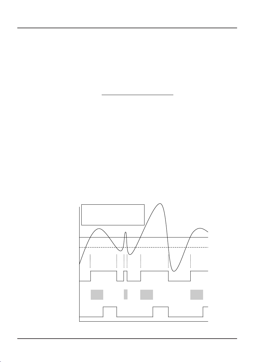
5.12 Menu 17 & 20 - OFF TO ON DELAY 1 & OFF TO ON DELAY 2
The trip condition must be seen for this delay before the relay can trip (see picture below).
(Default 5.0 seconds)
< T
SETPOINT 1
SETPOINT 1– HYS 1
10.0
9.8
RELAY 1 on above
SP1, with Off to On
time
dela
y
Tru e
False
Off to On Timer
RELAY 1
= T = T = T
HS510 USER GUIDE
QM015 Issue 1 18

5.13 Menu 18 & 21 - ON TO OFF DELAY 1 & ON TO OFF DELAY 2
The trip condition must not be seen for this delay before the relay can reset (see picture
below). (Default 0.5 seconds)
5.14 Menu 19 & 22 – ON DELAY 1 & ON DELAY 2
Relay must remain tripped for this delay before being allowed to reset (see picture below).
(Default 0.5 seconds)
SETPOINT 1
SETPOINT 1 – HYS 1
Tru e
False
On to Off Timer
RELAY 1
10.0
9.8
RELAY 1 on above SP1,
with On to Off time delay
= T
= T
< T
Tru e
False
On Timer
RELAY 1
SETPOINT 1
SETPOINT 1 – HYS 1
10.0
9.8
RELAY 1 on above SP1,
with On time dela
y
= T
= T
= T
= T
HS510 USER GUIDE
QM015 Issue 1
19

Page 19
All 3 delays (or any combination) can be used at the same time if desired. Note that if the
relay is tripped, both the ‘on delay’ timer and the ‘on to off delay’ timer can hold the relay
in the tripped condition until both have expired (see picture below).
6. RE-CONFIGURING THE OUTPUT AND INPUT
To change the input and output settings from the default 4-20mA it is necessary to remove the HS-
510 from its outer case. To open the HS-510, two catches located just below the outer terminal
blocks must be pushed in gently, one at a time. The front of the case can then be pulled and the
unit will withdraw from the cover.
Press here gently
SETPOINT 1
SETPOINT1 – HYS 1
= T = T
True
False
Off to On Timer
On Timer
On to Off Timer
RELAY 1
10.0
9.8
RELAY 1 on above SP1,
with
all
3
time
dela
y
s
=
= T
< T
= T
=
= T
T
!
! WARNING !
DO NOT OPEN UNIT OR ADJUST SWITCHES WITH
POWER SUPPLY, INPUT OR OUTPUT CONNECTED
HS510 USER GUIDE
QM015 Issue 1 20
Table of contents
Popular Amplifier manuals by other brands


Engl
Engl Savage 60 operating manual

Redback
Redback A 4920 operating manual

Western Electric
Western Electric 92-B Instructions for use

Sony
Sony XM-604EQX Marketing Specifications operating instructions

DR. Z Amplification
DR. Z Amplification CAZ-45 Series manual

Kollmorgen
Kollmorgen SERVOSTAR S300 Technical description