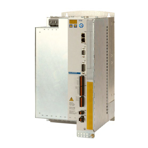
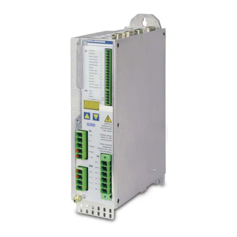
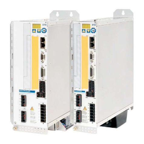
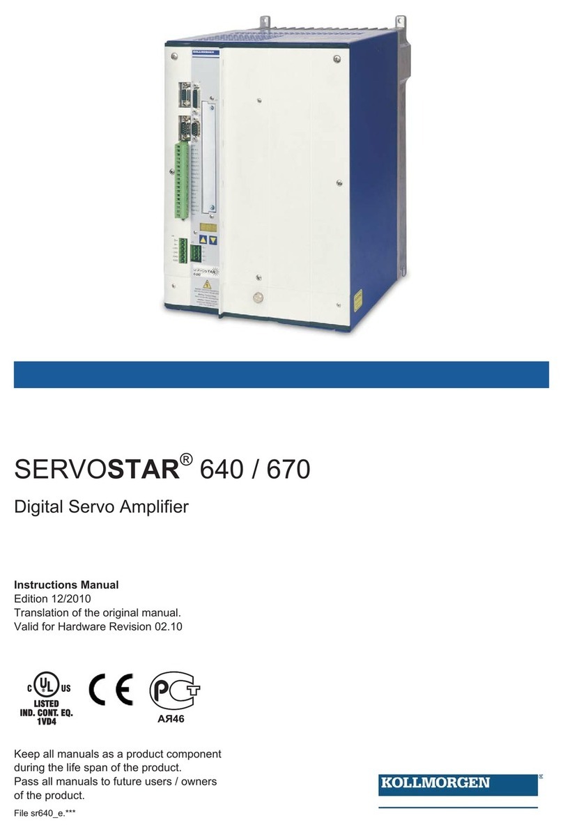
Kollmorgen SERVOSTAR S300 Parts list manual

Technical Description
DEUTSCH I/O - Erweiterungskarte
ENGLISH I/O- Expansion Card
FRANÇAIS I/O- Carte d'Expansion
ITALIANO I/O- Scheda di Espansione
S300 & S600 & S700 Servo Amplifiers
Edition: March 2021
For safe and proper use, follow
these instructions.
Keep them for future reference.

Contents
Deutsch (➜# 3) Français (➜# 11)
English (➜# 7) Italiano (➜# 15)
Documents available from www.kollmorgen.com
Instructions Manual (PDF format):
This manual provides instructions for installation and servo amplifier setup.
Accessories Manual (PDF format):
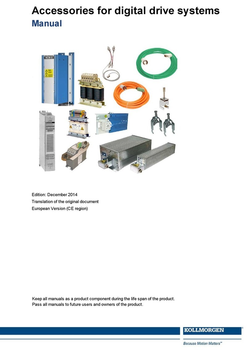
It provides information for accessories like cables, filters, chokes and brake resistors.
CAN-BUS Fieldbus Interface (PDF format):
Describes how to use your servo amplifier in CANopen applications.
DeviceNET Fieldbus Interface (PDF format):
Describes how to use your servo amplifier in DeviceNET applications.
EtherCAT Fieldbus Interface (PDF format):
Describes how to use your servo amplifier in EtherCAT applications.
PROFIBUS DP Fieldbus Interface (PDF format):
Describes how to use your servo amplifier in PROFIBUS DP applications.
PROFINET Fieldbus Interface (PDF format):
Describes how to use your servo amplifier in PROFINET applications.
sercos®2 Fieldbus Interface (PDF format):
Describes how to use your servo amplifier in sercos®applications.
SynqNet Fieldbus Interface (PDF format):
Describes how to use your servo amplifier in SynqNet applications.
DRIVEGUI.EXE Online help (CHMs format):
The online help includes the ASCII Object Reference which provides information for the parameters and
commands used to setup the servo amplifier.
Technical changes which improve the performance of the device may be made without prior notice!
This document is the intellectual property of Kollmorgen. All rights reserved. No part of this work may be reproduced
in any form (by photocopying, microfilm or any other method) or stored, processed, copied or distributed by electronic
means without the written permission of Kollmorgen.
2 Kollmorgen | kdn.kollmorgen.com | March 2021

1 Erweiterungskarte -I/O-14/08-
Dieses Kapitel beschreibt die zusätzlichen Eigenschaften, die die Erweiterungskarte dem
Servoverstärker verleiht.
Die -I/O-14/08- stellt Ihnen 14 zusätzliche digitale Eingänge und 8 digitale Ausgänge zur Ver-
fügung. Die Funktion der Ein- und Ausgänge ist über die Inbetriebnahme-Software ein-
stellbar.
Die 24VDC Versorgungsspannung muss von einer potentialgetrennten (z.B. mit Trenn-
transformator) Spannungsquelle zur Verfügung gestellt werden.
Die Ein- und Ausgänge werden verwendet, um im Servoverstärker gespeicherte Fahrauf-
träge zu starten und Meldungen des integrierten Lagereglers in der übergeordneten Steuerung
auszuwerten. Die Funktion der Eingänge und Meldeausgänge entspricht den Funktionen, die
den digitalen I/O's an Stecker X3 des zugeordnet werden können. Alle Ein- und Ausgänge
sind durch Optokoppler getrennt und potentialfrei gegenüber dem Servoverstärker.
1.1 Frontansicht
1.2 Einbau
Schalten Sie die Geräte vor Beginn der Arbeiten spannungsfrei.
Hebeln Sie die Abdeckung des Optionsschachtes mit einem geeigneten Schrau-
bendreher heraus.
Achten Sie darauf, dass keine Kleinteile (Schrauben o.ä.) in den geöffneten Opti-
onsschacht fallen.
Stecken Sie die Erweiterungskarte in den Schacht.
Verschrauben Sie die Frontplatte der Erweiterungskarte mit den vorgesehenen Schrau-
ben.
Technical Description | 1 Erweiterungskarte -I/O-14/08-
Kollmorgen | kdn.kollmorgen.com | March 2021 3

Technical Description | 1 Erweiterungskarte -I/O-14/08-
1.3 Technische Daten
Steuereingänge 24V / 7mA , SPS-kompatibel, EN 61131
Meldeausgänge 24V / max. 500mA , SPS-kompatibel, EN 61131
Versorgungseingänge nach
EN 61131
24V (18...36V) / 100mA plus Summenstrom der Ausgänge
(abhängig von der Eingangsschaltung der Steuerung).
Absicherung (extern) 4 AT
Stecker MiniCombicon, 12-polig, kodiert an PIN1 bzw. 12
Leitung Daten - bis 50m Länge : 22 x 0,5mm², nicht geschirmt,
Versorgung - 2 x 1mm², Spannungsverluste beachten
Wartezeit zwischen 2 Fahr-
aufträgen
abhängig von der Reaktionszeit der Steuerung
Adressierzeit (min.) 4ms
Startverzögerung (max.) 2ms
Reaktionszeit dig. Ausgänge max. 10ms
Die 24VDC Versorgungsspannung muss von einer potentialgetrennten (z.B. mit Trenn-
transformator) Spannungsquelle zur Verfügung gestellt werden.
1.4 Leuchtdioden
Neben den Klemmen der Erweiterungskarte sind zwei Leuchtdioden angebracht. Die grüne
Leuchtdiode meldet das Vorhandensein der erforderlichen 24V Hilfsspannung für die Erwei-
terungskarte. Die rote Leuchtdiode meldet Fehler in den Ausgängen der Erweiterungskarte
(Überlastung der Schalterbausteine und Kurzschluss).
1.5 Eingeben einer Fahrsatznummer (Beispiel)
Fahrsatznummer A7 A6 A5 A4 A3 A2 A1 A0
binär 1010 1110 1 0 1 0 1 1 1 0
dezimal 174 128 - 32 - 8 4 2 -
4 Kollmorgen | kdn.kollmorgen.com | March 2021

1.6 Steckerbelegung (Default)
Die Funktionen sind mit Hilfe der Setup-Software einstellbar.
Pin Dir Default Beschreibung
Stecker X11A
1 Ein A0 Fahrsatznummer 20, LSB
2 Ein A1 Fahrsatznummer 21
3 Ein A2 Fahrsatznummer 22
4 Ein A3 Fahrsatznummer 23
5 Ein A4 Fahrsatznummer 24
6 Ein A5 Fahrsatznummer 25
7 Ein A6 Fahrsatznummer 26
8 Ein A7 Fahrsatznummer 27, MSB
9 Ein Referenz
Abfrage des Referenzschalters. Wird ein digitaler Eingang am
Grundgerät als Referenzeingang verwendet, wird der Eingang an
der I/O-Erweiterungskarte nicht ausgewertet.
10 Ein S_fehl_clear Warnung Schleppfehler (n03) und Ansprechüberwachung (n04)
löschen
11 Ein FStart_Folge
Der im Fahrsatz definierte Folgeauftrag mit der Einstellung “Star-
ten über I/O” wird gestartet. Die Zielposition des aktuellen Fahr-
satzes muss erreicht sein, bevor der Folgefahrauftrag gestartet
werden kann.
12 Ein FStart_Tipp x
Starten der Einricht-Betriebsarzt "Tippbetrieb". "x" ist die im Ser-
voverstärker gespeicherte Geschwindigkeit für die Funktion Tipp-
betrieb. Eine steigende Flanke startet die Bewegung, eine
fallende Flanke bricht die Bewegung ab.
Stecker X11B
1 Ein FRestart Setzt den zuletzt abgebrochenen Fahrauftrag fort.
2Ein FStart_I/O
Startet den Fahrauftrag, der über die Eingänge A0-A7 (Stecker
X11A/1 bis X11A/8) adressiert ist. Falls kein Fahrauftrag adres-
siert ist, wird die Referenzfahrt gestartet.
3Aus InPosition
Das Erreichen der Zielposition (In-Positions-Fenster) eines Fahr-
auftrages wird durch Ausgabe eines High-Signals gemeldet. Ein
Kabelbruch wird nicht erkannt.
4 Aus Folge-InPos
Der Start jedes Fahrauftrages in einer automatisch nacheinander
ausgeführten Folge von Fahraufträgen wird durch Invertieren des
Ausgangssignals gemeldet. Beim Start des ersten Fahrauftrages
gibt der Ausgang ein Low-Signal aus. Die Meldeform wird über
ASCII-Kommandos variiert.
PosReg 0 Nur über ASCII-Kommandos einstellbar.
5 Aus S_fehl Das Verlassen des eingestellten Schleppfehler-Fensters wird mit
einem Low-Signal gemeldet.
6 Aus PosReg1 default: SW Endschalter 1, wird mit High-Signal gemeldet
7 Aus PosReg2 default: SW Endschalter 2, wird mit High-Signal gemeldet
8 Aus PosReg3 Nur über ASCII-Kommandos einstellbar.
9 Aus PosReg4 Nur über ASCII-Kommandos einstellbar.
10 Aus PosReg5 Nur über ASCII-Kommandos einstellbar
11 - 24V DC Spannungsversorgung für Ausgangssignale
12 - I/O-GND digital-GND der Steuerung
Technical Description | 1 Erweiterungskarte -I/O-14/08-
Kollmorgen | kdn.kollmorgen.com | March 2021 5

Technical Description | 1 Erweiterungskarte -I/O-14/08-
1.7 Anschlussbild (Default)
Beim SERVOSTAR 600 müssen zusätzlich AGND und DGND (Stecker X3) gebrückt wer-
den!
6 Kollmorgen | kdn.kollmorgen.com | March 2021

2 Expansion card -I/O-14/08-
This section describes the additional features that the expansion card -I/O-14/08- provides
for the servo amplifier.
The -I/O-14/08- provides you with 14 additional digital inputs and 8 digital outputs. The func-
tions of the inputs and outputs are adjustable with the setup software.
The 24V DC voltage must be supplied by an electrically isolated power supply (e.g. with iso-
lating transformer).
The I/Os are used to initiate the motion tasks that are stored in the servo amplifier and to
evaluate signals from the integrated position control in the higher-level control system. The
functions of the inputs and signal outputs correspond to the functions that can be assigned to
the digital I/Os on connector X3. All inputs and outputs are electrically isolated from the servo
amplifier by optocouplers.
2.1 Front view
2.2 Installation
Before starting work, switch off the power to the device
Use a suitable screwdriver to lever off the cover of the option slot.
Take care that no small items (such as screws) fall into the open option slot.
Push the expansion card into the slot.
Use the screws provided to fasten the front plate of the expansion card in place.
Technical Description | 2 Expansion card -I/O-14/08-
Kollmorgen | kdn.kollmorgen.com | March 2021 7

Technical Description | 2 Expansion card -I/O-14/08-
2.3 Technical data
Control inputs 24V / 7mA , PLC compatible, IEC 61131
Signal output 24V / max. 500mA , PLC compatiblel, IEC 61131
Supply inputs, to IEC 61131 24V (18...36V) / 100mA plus total current of the outputs
(depends on the input wiring of the controls)
Fusing (external) 4 AT
Connectors MiniCombicon, 12-pin, coded on PIN1 and 12
Cables Data – up to 50m long : 22 x 0.5 mm², unshielded,
Supply – 2 x 1mm², check voltage drop
Waiting time between
2 motion tasks
Depends on the response time of the control system
Addressing time (minimum) 4ms
Starting delay (maximum) 2ms
Response time of digital
outputs
max. 10ms
The 24VDC voltage has to be supplied by an electrically isolated power supply, e.g. with
insulating transformer.
2.4 LEDs
Two LEDs are mounted next to the terminals on the expansion card. The green LED signals
that the 24V auxiliary supply is available for the expansion card. The red LED signals faults in
the outputs from the expansion card (overload of switching components, short-circuit).
2.5 Entering a motion block number (example)
Motion block number A7 A6 A5 A4 A3 A2 A1 A0
binary 1010 1110 1 0 1 0 1 1 1 0
decimal 174 128 - 32 - 8 4 2 -
8 Kollmorgen | kdn.kollmorgen.com | March 2021

2.6 Connector assignments
The functions are adjustable with the setup software.
Pin Dir Default Description
Connector X11A
1 In A0 Motion block number 20, LSB
2 In A1 Motion block number 21
3 In A2 Motion block number 22
4 In A3 Motion block number 23
5 In A4 Motion block number 24
6 In A5 Motion block number 25
7 In A6 Motion block number 26
8 In A7 Motion block number 27, MSB
9 In Reference
Polls the home switch. If a digital input on the base unit is used as
a home input, then the input on the expansion card will not be eva-
luated.
10 In F_error_clear Clears the warning of a following error (n03) or the response moni-
toring (n04)
11 In F_error_clear
The following task, that is defined in the motion task by “Start with
I/O” is started. The target position of the present motion task must
be reached before the following task can be started. The next
motion block can also be started by an appropriately configured
digital input on the base unit.
12 In Start_Jog v=
x
Starts the "Jog Mode" with a defined speed. “x” is the speed
saved in the servo amplifier for the function "Jog Mode". A rising
edge starts the motion, a falling edge cancels the motion.
Connector X11B
1 In MT_Restart Continues the motion task that was previously interrupted.
2 Out Start_MT I/O
Starts the motion task that is addressed by A0-A7 (connector
X11A/1 to X11A8). If no motion task is addressed, then a homing
task is started.
3 Out InPos
When the target position for a motion task has been reached (the
InPosition window), this is signaled by the output of a HIGH
signal. A cable break will not be detected.
4 Out Next-InPos
The start of each motion task in an automatically executed
sequence of motion tasks is signaled by an inversion of the output
signal. The output produces a LOW signal at the start of the first
motion task of the sequence. The form of the message can be
varied by using ASCII commands.
PosReg 0 Can be adjusted by ASCII commands only.
5 Out F_error A LOW signal indicates that the position has gone outside the
acceptable following error window.
6 Out PosReg1 default: SW limit 1, indicated by a HIGH signal
7 Out PosReg2 default: SW limit 2, indicated by a HIGH signal
8 Out PosReg3 Can only be adjusted by ASCII commands
9 Out PosReg4 Can only be adjusted by ASCII commands
10 Out PosReg5 Can only be adjusted by ASCII commands
11 - 24V DC Supply voltage for output signals.
12 - I/O-GND Digital GND for the control system.
Technical Description | 2 Expansion card -I/O-14/08-
Kollmorgen | kdn.kollmorgen.com | March 2021 9

Technical Description | 2 Expansion card -I/O-14/08-
2.7 Connection diagram (default)
With SERVOSTAR 600 terminals AGND and DGND (connector X3) must be joined
together !
10 Kollmorgen | kdn.kollmorgen.com | March 2021

3 Carte d'expansion -I/O-14/08-
Ce chapitre décrit les cartes d'expansion d'entrée/sortie -I/O-14/08-. La description ne porte
toutefois que sur les caractéristiques supplémentaires que la carte d'expansion ajoute au
variateur. La carte -I/O-14/08- permet en outre de disposer de 14 entrées numériques et de 8
sorties numériques supplémentaires. La fonction des entrées et des sorties est définie à
l’avance.
La tension d'alimentation de 24 V CC doit être disponible à partir d'une source gal-
vaniquement isolée (p. ex. transformateur d'isolation).
Les entrées/sorties sont utilisées pour lancer des instructions de mouvement mémorisées
dans le variateur et pour exploiter les informations transmises par le régulateur de position
intégré sur la commande hiérarchiquement supérieure. La fonction des entrées et des sorties
de signalisation correspond aux fonctions pouvant être affectées aux entrées/sorties numéri-
ques du connecteur X3 du variateur. Toutes les entrées et sorties sont isolées élec-
triquement par optocoupleurs et présentent donc un potentiel flottant par rapport au variateur.
3.1 Vue de face
3.2 Montage
Avant de commencer le travail, mettez l'appareil hors tension.
Soulever le couvercle de l’emplacement des options à l’aide d’un tournevis approprié.
S’assurer qu’aucune petite pièce (vis ou autres) ne chute dans l’emplacement ouvert.
Enfichez la carte d’expansion dans le port.
Vissez la face avant de la carte d’expansion à l’aide des vis prévues à cet effet.
Technical Description | 3 Carte d'expansion -I/O-14/08-
Kollmorgen | kdn.kollmorgen.com | March 2021 11

Technical Description | 3 Carte d'expansion -I/O-14/08-
3.3 Données techniques
Entrées de commande 24V / 7mA , compatible API, EN 61131
Sorties de signalisation 24V / max. 500mA , compatible API, EN 61131
Entrées d’alimentation selon EN
61131
24V (18...36V) / 100mA plus courant additionnel des sor-
ties (en fonction du circuit d’entrée de API)
Protection (externe) 4 AT
Connecteur MiniCombicon, 12 broches, codé sur PIN1 ou 12
Câble données: jusqu’à 50m de long : 22x0,5mm², non blindé;
alimentation: 2x1mm², tenir compte des chutes de ten-
sion
Délai d’attente entre 2 tâches de
mouvement
dépend du temps de réaction de la commande
Délai d’adressage (min.) 4ms
Temporisation au démarrage max. 2ms
Temps de réaction, sorties num. max. 10ms
La tension d'alimentation 24VDC doivent être mis à la disposition par (p. ex. avec le trans-
formateur de séparation) une source de tension séparé de potentiel.
3.4 Diodes électroluminescentes (DEL)
Deux DEL sont disposées à côté des bornes de la carte d'expansion. L'allumage de la DEL
signale la présence de la tension d'alimentation de 24V destinée à la carte d'expansion.
L'allumage de la DEL rouge signale l'existence d'un défaut sur l'une des sorties de la carte
d'expansion (surcharge des composants de commutation ou court-circuit).
3.5 Sélectionner le n° de profil de mouvement
N° de profil de mouvement A7 A6 A5 A4 A3 A2 A1 A0
binaire 1010 1110 1 0 1 0 1 1 1 0
décimal 174 128 - 32 - 8 4 2 -
12 Kollmorgen | kdn.kollmorgen.com | March 2021

3.6 Affectation des connecteurs (par défaut)
Les fonctions peuvent être réglées à l’aide du logiciel setup.
Pin Dir Default Description
Connecteur X11A
1 Entrée A0 N° de profil de mouvement 20, LSB
2 Entrée A1 N° de profil de mouvement 21
3 Entrée A2 N° de profil de mouvement 22
4 Entrée A3 N° de profil de mouvement 23
5 Entrée A4 N° de profil de mouvement 24
6 Entrée A5 N° de profil de mouvement 25
7 Entrée A6 N° de profil de mouvement 26
8 Entrée A7 N° de profil de mouvement 27, MSB
9 Entrée Référence
Interrogation du commutateur de référence. Si une entrée numéri-
que est utilisée comme entrée de référence sur l’appareil de base,
l’entrée sur la carte d’expansion E/S ne sera pas analysée.
10 Entrée FError_
clear
Effacement d’un avertissement d’erreur de poursuite (n03) ou
d’une surveillance de déclenchement.
11 Entrée Start_MT
Next
L’instruction suivante définie dans le profil de mouvement est
émise par le réglage “Démarrage par I/O”. La position de des-
tination du profil de mouv. doit être atteinte avant que l’instruction
de démarrage du mouvement suivant puisse être émise.
12 Entrée Start_Jog
x
Démarrage du mode de fonctionnement de réglage “Mode pas à
pas”. “x” correspond à la vitesse enregistrée dans le variateur pour
la fonction mode pas à pas. Un front montant lance le mouvement,
un front descendant l’interrompt.
Connecteur X11B
1 Entrée FRestart Poursuit la tâche de mouvement précédemment interrompue.
2Entrée Start_MT
I/O
Démarrage de la tâche de mouvement adressée via les entrées
A0-A7 (connecteurs X11A/1 à X11A/8). En l’absence d’adressage
de la tâche de mouvement, le trajet de référence démarre.
3Sortie InPos
L’atteinte de la position de destination (fenêtre In-Position) d’une
tâche de mouvement est signalée par l’émission d’un signal haut.
Une rupture de câble n’est pas détectée.
4 Sortie
Next_
InPos
Le démarrage de chaque tâche de mouvement dans une séquence
automatique constituée d’une succession de tâches de mou-
vement est signalé par l’inversion du signal de sortie. Au démar-
rage de la première tâche de mouvement, la sortie émet un signal
bas.La forme de cette signalisation peut être modifiée à l’aide de
commandes ASCII.
PosReg 0 Ne peut être réglé que par des instructions ASCII.
5 Sortie FError La sortie de la fenêtre d’erreur de poursuite réglée est signalée par
l’émission d’un signal de niveau logique bas.
6 Sortie PosReg1 défaut: interrupteur de fin de course 1, indiqué par un signal haut
7 Sortie PosReg2 défaut: interrupteur de fin de course 2, indiqué par un signal haut
8 Sortie PosReg3 Ne peut être réglé que par des instructions ASCII.
9 Sortie PosReg4 Ne peut être réglé que par des instructions ASCII.
10 Sortie PosReg5 Ne peut être réglé que par des instructions ASCII.
11 - 24V DC Tension d’alimentation des signaux de sortie
12 - I/O-GND Terre numérique (GND) de la commande
Technical Description | 3 Carte d'expansion -I/O-14/08-
Kollmorgen | kdn.kollmorgen.com | March 2021 13

Technical Description | 3 Carte d'expansion -I/O-14/08-
3.7 Schéma de raccordement (par defaut)
Avec SERVOSTAR 600 AGND et DGND (connecteur X3) doivent être strappés !
14 Kollmorgen | kdn.kollmorgen.com | March 2021

4 Scheda di espansione -I/O-14/08-
Questo capitolo descrive la scheda di espansione I/O-14/08-. Sono descritte esclusivamente
le proprietà aggiuntive che la scheda di espansione conferisce al servoamplificatore.
La -I/O-14/08- mette a disposizione 14 ingressi digitali e 8 uscite digitali aggiuntive. La fun-
zione degli ingressi e delle uscite è impostata.
La tensione di alimentazione da 24VCC deve essere messa a disposizione da una fonte di
tensione con separazione di potenziale (ad es. con trasformatore di disaccoppiamento).
Gli ingressi/uscite si utilizzano per avviare task di movimento memorizzati nel ser-
voamplificatore e per valutare i messaggi del regolatore di posizione integrato nell'unità di con-
trollo subordinata. La funzione degli ingressi e delle uscite dei segnali corrisponde alle
funzioni che possono essere assegnate agli I/O digitali sul connettore X3 servoamplificatore.
L'alimentazione della scheda di espansione con 24V CC avviene tramite il controllo. Tutti gli
ingressi e le uscite sono isolate mediante optoaccoppiatori e a potenziale zero rispetto al ser-
voamplificatore.
4.1 Vista frontale
4.2 Montaggio
Prima di iniziare il lavoro, spegnere il dispositivo.
Utilizzare un cacciavite adatto per rimuovere il coperchio dello slot opzionale.
Fare attenzione che nessun piccolo oggetto (come le viti) cada nello slot opzionale
aperto.
Inserire la scheda di espansione nello slot.
Avvitare la piastra frontale della scheda di espansione con le viti in dotazione.
Technical Description | 4 Scheda di espansione -I/O-14/08-
Kollmorgen | kdn.kollmorgen.com | March 2021 15

Technical Description | 4 Scheda di espansione -I/O-14/08-
4.3 Dati tecnici
Ingressi di comando 24V / 7mA , PLC compatibile, EN 61131
Uscite dei segnali 24V / max. 500mA , PLC compatibile, EN 61131
Ingressi alimentazione con-
formi a EN 61131
24V (18...36V) / 100 mA più corrente cumulativa delle uscite
(a seconda del circuito in entrata del controllo).
Protezione (esterna) 4 AT
Connettori MiniCombicon, a 12 poli, codificato su PIN1 o 12
Cavo Dati - fino a 50 m di lunghezza: 22 x 0,5 mm², non schermato,
alimentazione - 2 x 1 mm², prestare attenzione alle eventuali
cadute di tensione
Attesa fra 2 task di movi-
mento
a seconda del tempo di reazione del controllo
Tempo di indirizzamento
(min.)
4ms
Ritardo avviamento (max.) 2ms
Tempo di reazione uscite digi-
tali
max. 10ms
La tensione di alimentazione 24VDC deve essere fornita da una fonte di tensione separata
da potenziale (ad es. con un trasformatore di isolamento).
4.4 Diodi luminosi
Accanto ai morsetti della scheda di espansione sono stati applicati due LED. Il LED verde
segnala la disponibilità della tensione ausiliaria di 24 V necessaria per la scheda di espan-
sione. Il LED rosso segnala eventuali errori sulle uscite della scheda di espansione (sovrac-
carico degli elementi del commutatore e cortocircuito).
4.5 Selezionare il codice di task di movimento (esempio)
Codice del task di movimento A7 A6 A5 A4 A3 A2 A1 A0
binario 1010 1110 1 0 1 0 1 1 1 0
decimale 174 128 - 32 - 8 4 2 -
16 Kollmorgen | kdn.kollmorgen.com | March 2021

4.6 Assegnazione dei connettori
Le funzioni sono registrabili con il software di messa a punto.
Pin Dir Default Descrizione
Connettore X11A
1 Ingresso A0 Codice del record di movimento 20, LSB
2 Ingresso A1 Codice del record di movimento 21
3 Ingresso A2 Codice del record di movimento 22
4 Ingresso A3 Codice del record di movimento 23
5 Ingresso A4 Codice del record di movimento 24
6 Ingresso A5 Codice del record di movimento 25
7 Ingresso A6 Codice del record di movimento 26
8 Ingresso A7 Codice del record di movimento 27, MSB
9 Ingresso Reference
Richiesta del commutatore di riferimento Se si utilizza un
ingresso digitale sul dispositivo di base come ingresso di rife-
rimento, l’ingresso della scheda I/O non sarà rilevato.
10 Ingresso F_error_clear Errore di inseguimento n03 o annulla controllo intervento n04.
11 Ingresso Start_MT_
Next
Il task di sequenza definito nel record di movimento con l’im-
postazione “Avvia tramite I/O” viene eseguito. La posizione
d’arrivo del record di movimento corrente deve essere raggi-
unta prima dell’avvio del task di sequenza. Il task di movimen-
to in sequenza può essere avviato anche con un ingresso digi-
tale appositamente definito nel dispositivo di base.
12 Ingresso Start_Jog
v=x
Avviare il modo di funzionamento per la messa a punto “Velo-
cità costante”. “x” rappresenta la velocità memorizzata nel
amplificatore per la funzione VELOCITÀ COSTANTE. Una
rampa in salita avvia il movimento, una rampa in discesa inter-
rompe il movimento.
Connettore X11B
1 Ingresso FRestart Riprende l’ultimo task di movimento interrotto.
2 Ingresso Start_MT
I/O
Avvio del task di movimento, che risulta indirizzato su A0-A7
(connettore X11A/1-X11A/8). Se non è indirizzato alcun task
di movimento, viene avviata la corsa al punto di riferimento
3 Uscita InPos
Il raggiungimento della posizione d’arrivodi un task di movi-
mento viene segnalato tramite l’emissione di un segnale alto.
La rottura dei cavi non viene riconosciuta.
4 Uscita Next-InPos
L’avvio di ogni task di movimento facente parte di una
sequenza eseguita automaticamente viene segnalato
dall’inversione del segnale di uscita. All’avviamento del primo
task di movimento della sequenza, l’uscita emette un segnale
basso. La forma dei segnali può essere modificata servendosi
dei comandi ASCII.
PosReg 0 Impostazione possibile soltanto per comandi ASCII.
5 Uscita F_error L’uscita dalla finestra Errore di inseguimento impostata viene
segnalato con un segnale basso.
6 Uscita PosReg1 Impostazione predeinita: finecorsa SW 1, indicato con High.
7 Uscita PosReg2 Impostazione predeinita: finecorsa SW 2, indicato con High.
8 Uscita PosReg3 Impostazione possibile soltanto per comandi ASCII
9 Uscita PosReg4 Impostazione possibile soltanto per comandi ASCII
10 Uscita PosReg5 Impostazione possibile soltanto per comandi ASCII
11 Alim. 24V DC Alimentazione per il segnale d’ingresso
12 Alim. I/O-GND GND digitale del controllo
Technical Description | 4 Scheda di espansione -I/O-14/08-
Kollmorgen | kdn.kollmorgen.com | March 2021 17

Technical Description | 4 Scheda di espansione -I/O-14/08-
4.7 Schema collegamenti (Default)
Con il SERVOSTAR 600 è necessario ponticellare anche AGND e DGND (connettore X3)!
18 Kollmorgen | kdn.kollmorgen.com | March 2021

-- / --
Technical Description |
Kollmorgen | kdn.kollmorgen.com | March 2021 19

Service
Kollmorgen bietet seinen Kunden einen umfassenden Kundendienst.
.
Besuchen Sie das Kollmorgen Developer Network. Stellen Sie Fra-
gen an die Community, durchsuchen Sie die "Knowledge Base",
laden Sie Dateien herunter und schlagen Sie Verbesserungen vor.
Europa
KOLLMORGEN
Internet: www.kollmorgen.com/de-de
E-Mail: technik@kollmorgen.com
Tel.: +49 - 2102 - 9394 - 0
Fax: +49 - 2102 - 9394 - 3155
Nordamerika
KOLLMORGEN
Internet: www.kollmorgen.com/en-us
E-Mail: support@kollmorgen.com
Tel.: +1 - 540 - 633 - 3545
Fax: +1 - 540 - 639 - 4162
Südamerika
KOLLMORGEN
Internet: www.kollmorgen.com/pt-br
E-Mail: contato@kollmorgen.com
Tel.: +55 - 11 - 4615-6300
Asien
KOLLMORGEN
Internet: www.kollmorgen.cn
E-Mail: sales.china@kollmorgen.com
Tel: +86 - 400 668 2802
Fax: +86 - 21 6248 5367
Other manuals for SERVOSTAR S300
6
This manual suits for next models
2
Table of contents
Languages:
Other Kollmorgen Amplifier manuals

Kollmorgen
Kollmorgen SILVERLINE S/O Series User manual

Kollmorgen
Kollmorgen S70601-SE User manual

Kollmorgen
Kollmorgen S700 Series User manual

Kollmorgen
Kollmorgen SERVOSTAR 300 User manual

Kollmorgen
Kollmorgen SERVOSTAR 601 User manual

Kollmorgen
Kollmorgen SERVOSTAR 300 User manual

Kollmorgen
Kollmorgen AKD series User manual

Kollmorgen
Kollmorgen SERVOSTAR 614 User manual

Kollmorgen
Kollmorgen S772 User manual

Kollmorgen
Kollmorgen SERVOSTAR S300 User manual