Kramer TP-202 User manual

Kramer Electronics, Ltd.
USER MANUAL
Model:
TP-202
UXGA Line Transceiver/DA

Contents
i
Contents
1Introduction 1
2Getting Started 1
2.1Quick Start 2
3Overview 3
3.1About the Power Connect Feature 3
3.2Shielded Twisted Pair (STP)/Unshielded Twisted Pair (UTP) 4
3.3Recommendations for Achieving the Best Performance 4
4Your TP-202 UXGA Line Transceiver/DA 5
5Connecting the TP-202 7
5.1Wiring the CAT 5 LINE IN / LINE OUT RJ-45 Connectors 9
6Technical Specifications 9
Figures
Figure 1: TP-202 UXGA Line Transceiver/DA 5
Figure 2: TP-202 (Underside Panel) 6
Figure 3: Connecting the TP-202 8
Figure 4: CAT 5 PINOUT 9
Tables
Table 1: TP-202 UXGA Line Transceiver/DA Features 5
Table 2: TP-202 (Underside Panel) Features 6
Table 3: CAT 5 PINOUT 9
Table 4: Technical Specifications of the TP-202 9

Introduction
1
1 Introduction
Welcome to Kramer Electronics! Since 1981, Kramer Electronics has been
providing a world of unique, creative, and affordable solutions to the vast
range of problems that confront the video, audio, presentation, and
broadcasting professional on a daily basis. In recent years, we have
redesigned and upgraded most of our line, making the best even better! Our
1,000-plus different models now appear in 11 groups1that are clearly
defined by function.
Thank you for purchasing the Kramer TOOLS TP-202 UXGA Line
Transceiver/DA which is ideal for:
•Presentation and multimedia applications
•Long-range graphics distribution for schools, hospitals, security, and
stores
The package includes the following:
•TP-202 UXGA Line Transceiver/DA
•Power supply (12V DC)
•This user manual2
2 Getting Started
We recommend that you:
•Unpack the equipment carefully and save the original box and
packaging materials for possible future shipment
•Review the contents of this user manual
•Use Kramer high performance high-resolution cables3
1 GROUP 1: Distribution Amplifiers; GROUP 2: Switchers and Matrix Switchers; GROUP 3: Control Systems;
GROUP 4: Format/Standards Converters; GROUP 5: Range Extenders and Repeaters; GROUP 6: Specialty AV Products;
GROUP 7: Scan Converters and Scalers; GROUP 8: Cables and Connectors; GROUP 9: Room Connectivity;
GROUP 10: Accessories and Rack Adapters; GROUP 11: Sierra Products
2 Download up-to-date Kramer user manuals from our Web site at http://www.kramerelectronics.com
3 The complete list of Kramer cables is on our Web site at http://www.kramerelectronics.com

KRAMER: SIMPLE CREATIVE TECHNOLOGY
Getting Started
2
2.1 Quick Start
This quick start chart summarizes the basic setup and operation steps.
Step 1: Connect the input and the outputs
m
m
Set the polarity using the underside switches
Adjust the EQ. and LEVEL using the trimmers on the front panel
m
Set the polarity using the underside switches
m
Adjust the EQ. and LEVEL using the trimmers on the front panel
Step 2: Connect the power
Step 3: On the TP-202, if required:
1
1
2
2
3
3
3
4
4
4
Connect the input source to
the PT-110 transmitter
Connect the outputs: up to
two acceptors per unit
Connect the CAT 5 cable
between the transmitter
(PT-110) and the receiver
(TP-202)
Connect an additional
TP-202 via CAT 5 cable
Connect the input source to
the PT-110 transmitter
Connect the outputs: up to
two acceptors per unit
Connect the CAT 5 cable
between the transmitter
(PT-110) and the receiver
(TP-202)
Connect an additional
TP-202 via CAT 5 cable
Display 1 Display 4 Display 3
Long CAT 5 cable
TP-202
XGA Line Receiver/DA
12V DC
LO
INE UT
LI
INE N
XGA LineTransmitter
PT110
XGA INPUT
LINE OUTPUT
ON
Long CAT 5 cable
Computer Graphics
Source
VGA
Display 2
VGA VGAVGA
VGA

Overview
3
3 Overview
The TP-202 is a twisted pair branching receiver for computer graphics
video signals with resolutions from VGA up to UXGA and higher or HDTV
signals. It takes a twisted pair signal and converts it into a computer
graphics video signal or HDTV signal available on two 15-pin HD outputs,
and simultaneously re-transmits the original twisted pair signal to another
compatible receiver.
The TP-202 UXGA Line Transceiver/DA:
•Has a transmission range of more than 300ft. (more than 100 meters)
•Can receive HD signals (high-definition resolutions: 480p, 576p, 720p,
1080i and 1080p)
•Includes two XGA outputs on 15-pin HD connectors
•Includes EQ. and LEVEL controls
•Can change the polarity of decoding H and V Sync for UXGA graphics
•Is 12V DC fed and can power or be powered by the receiver over the
same CAT 5 cable (see section 3.1)
•Features a CAT 5 output for transmitting the signal to an additional
receiver
3.1 About the Power Connect Feature
The Power Connect feature applies as long as the cable can carry power.
This feature is available when using STP cable and the distance does not
exceed 50m on standard CAT 5 cable. For longer distances, heavy gauge
cable should be used1.For units which are connected via RJ-45 connectors,
make sure that the shield of the STP cable is connected to the metal casing
of the connectors on both ends of the cable. For units which are connected
via terminal block connectors, the shield of the STP cable must be
connected to a ground terminal on the units at both ends (use the ground
terminal of the power supply connection if necessary).
For a CAT 5 cable exceeding a distance of 50m, separate power supplies
should be connected to the transmitter and to the receiver simultaneously.
1 CAT 5 cable is still suitable for the video/audio transmission, but not for feeding the power at these distances

KRAMER: SIMPLE CREATIVE TECHNOLOGY
Overview
4
3.2 Shielded Twisted Pair (STP)/Unshielded Twisted Pair (UTP)
We recommend that you use Shielded Twisted Pair (STP) cable. There are
different levels of STP cable available, and we advise you to use the best
quality STP cable that you can afford. Our non-skew-free cable, Kramer
BC-STP is intended for analog signals where skewing is not an issue. For
cases where there is skewing, our UTP skew-free cable, Kramer BC-XTP,
may be used. Bear in mind, though, that we advise using STP cables where
possible, since the compliance to electromagnetic interference was tested
using those cables.
Although Unshielded Twisted Pair (UTP) cable might be preferred for long
range applications, the UTP cable should be installed far away from electric
cables, motors and so on, which are prone to create electrical interference.
However, since the use of UTP cable might cause inconformity to
electromagnetic standards, Kramer does not commit to meeting the standard
with UTP cable.
3.3 Recommendations for Achieving the Best Performance
•Use only good quality connection cables1to avoid interference,
deterioration in signal quality due to poor matching, and elevated noise
levels (often associated with low quality cables).
•Avoid interference from neighboring electrical appliances that may
adversely influence signal quality and position your Kramer TP-202
away from moisture, excessive sunlight and dust
1 Available from Kramer Electronics on our Web site at http://www.kramerelectronics.com

Your TP-202 UXGA Line Transceiver/DA
5
4 Your TP-202 UXGA Line Transceiver/DA
Figure 1 and Table 1 define the TP-202:
Figure 1: TP-202 UXGA Line Transceiver/DA
Table 1: TP-202 UXGA Line Transceiver/DA Features
# Feature Function
1 12V DC +12V DC connector for powering the unit
2 LINE IN RJ-45 Connector Connect2to the LINE OUT RJ-45 connector on the
transmitter1
3 LINE OUT RJ-45 Connector Connect2to the LINE IN connector on an additional TP-202
4 EQ. Trimmer Adjust3the cable compensation equalization level
5 LEVEL Trimmer Adjust3the output signal level
6 XGA OUT 1 15-pin HD Connector Connect to the first XGA acceptor
7 XGA OUT 2 15-pin HD Connector Connect to the second XGA acceptor
8 ON LED Illuminates when receiving power
1 For example, the PT-110, as Figure 3 illustrates
2 Using a UTP CAT 5 cable with RJ-45 connectors at both ends (the PINOUT is defined in Table 3 and Figure 4)
3 Insert a screwdriver into the small hole and carefully rotate it, to trim the appropriate level

KRAMER: SIMPLE CREATIVE TECHNOLOGY
Your TP-202 UXGA Line Transceiver/DA
6
Figure 2 and Table 2 define the TP-202 underside panel:
Figure 2: TP-202 (Underside Panel)
Table 2: TP-202 (Underside Panel) Features
# Feature Function
1 VS Switch Slide the switch to NORMAL to retain the polarity1
Slide the switch to INVERT to invertthe VS polarity
2 HS Switch Slide the switch to NORMAL to retain the polarity1
Slide the switch to INVERT to invert the HS polarity
1 By default, both switches are set to NORMAL

Connecting the TP-202
7
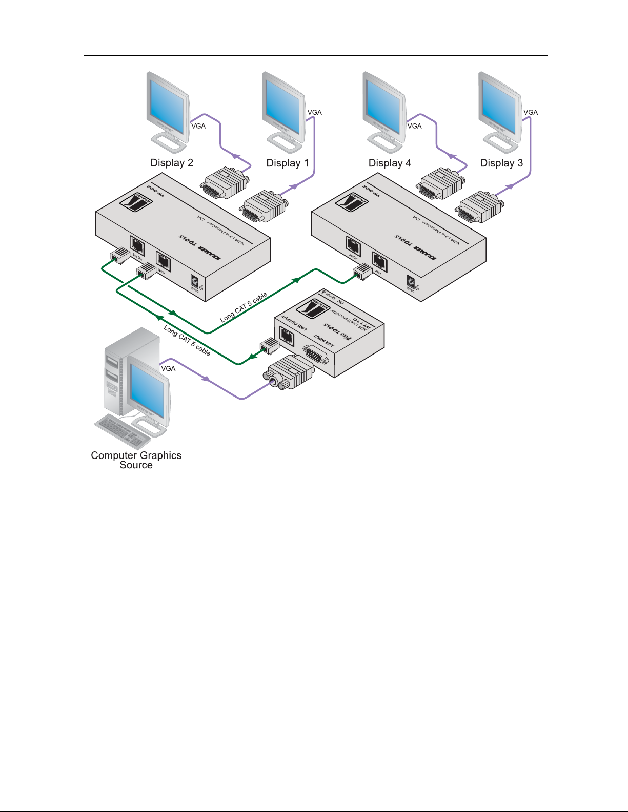
5 Connecting the TP-202
You can use the TP-202 UXGA Line Transceiver/DA to configure a UXGA
DA system. This will let you transmit a computer graphics signal to two
displays via long line CAT 5 UTP cabling1.
To connect the TP-202, as the example in Figure 3 illustrates, do the
following:
1. Connect a transmitter (for example, the Kramer PT-110 XGA Line
Transmitter2) to the LINE IN RJ-45 connector via CAT 5 cabling, see
section 5.1.
2. Set the VS and HS switches on the underside of the unit to NORMAL.
3. Connect the XGA OUT 1 15-pin HD connector to an XGA acceptor (for
example, display 1).
4. Connect the XGA OUT 2 15-pin HD connector to an XGA acceptor (for
example, display 2).
5. Check the image on the display. If it is not stable, set the VS and HS
switches to INVERT to obtain a stable image.
6. If required, connect the LINE OUT RJ-45 connector on the TP-202 to an
additional3TP-202.
7. If required, adjust4the video output signal level and/or cable compensation
equalization level.
8. If necessary, set the HS and VS switches on the TP-202 underside5.
9. Connect the 12V DC power adapter to the power socket and connect the
adapter to the mains electricity (not shown in Figure 3).
The signal from the UXGA source is transmitted via CAT 5 cable to the
TP-202, decoded and converted at the XGA OUT 1 and XGA OUT 2
15-pin HD connectors to the UXGA acceptors simultaneously.
When chaining several units, we recommend using an STP cable between the transmitter
and the receiver and a skew-free cable for connecting the TP-202 units.
When using the TP-202 as a standalone, we recommend using UTP cables.
1 By using two TP-202 units, you can transmit the signal to an additional TP-202
2 You can also connect an HD transmitter, such as the Kramer TP-219HD
3 Up to six units may be connected with minimal deterioration. The combined length between the first and the last unit may
exceed 300 meters
4 Use a screwdriver to carefully rotate the trimmer, adjusting the appropriate level
5 By default, both switches are set to normal (see Figure 2 and Table 2)

KRAMER: SIMPLE CREATIVE TECHNOLOGY
Connecting the TP-202
8
Figure 3: Connecting the TP-202

Technical Specifications
9
5.1 Wiring the CAT 5 LINE IN / LINE OUT RJ-45 Connectors
Table 3 and Figure 4 define the UTP CAT 5 PINOUT, using a straight pin
to pin cable with RJ-45 connectors:
Table 3: CAT 5 PINOUT Figure 4: CAT 5 PINOUT
EIA /TIA 568A EIA /TIA 568B
PIN Wire Color PIN Wire Color
1 Green / White 1 Orange / White
2 Green 2 Orange
3 Orange / White 3 Green / White
4 Blue 4 Blue
5 Blue / White 5 Blue / White
6 Orange 6 Green
7 Brown / White 7 Brown / White
8 Brown 8 Brown
Pair 1 4 and 5 Pair 1 4 and 5
Pair 2 3 and 6 Pair 2 1 and 2
Pair 3 1 and 2 Pair 3 3 and 6
Pair 4 7 and 8 Pair 4 7 and 8
6 Technical Specifications
Table 4 includes the technical specifications1.
Table 4: Technical Specifications2of the TP-202
INPUTS: 1 CAT 5 LINE IN on an RJ-45 connector
OUTPUTS: 1 CAT 5 LINE OUT on an RJ-45 connector
2 XGA on 15-pin HD connectors
MAX. OUTPUT LEVEL: 1.5Vpp
RESOLUTION: Up to UXGA, up to 1080p
DIFF. GAIN: 2.8%
DIFF. PHASE: 0.2Deg
K-FACTOR: 0.1%
S/N RATIO: 69.2dB @5MHz
CONTROLS: Level: -9.6dB to +2.3dB; Equalization: 0dB to 36.3dB @50MHz
COUPLING: Receiver section: DC, looping section: AC
POWER SOURCE: 12V, 525mA maximum current3
DIMENSIONS: 12.1cm x 7.18cm x 2.42cm (4.76" x 2.83" x 0.95"), W, D, H
WEIGHT: 0.3kg (0.67lbs) approx.
ACCESSORIES: Power supply
1 Specifications are subject to change without notice
2 Specifications are guaranteed for a system of two connected machines
3 When feeding TP-219HD (as the transmitter) and a looped TP-202

KRAMER: SIMPLE CREATIVE TECHNOLOGY
10
LIMITED WARRANTY
WHOISPROTECTED?
WHATISCOVEREDANDWHATISNOTCOVERED
WHATWEWILLPAYFORANDWHATWEWILLNOTPAYFOR
HOW YOU CAN GET WARRANTY SERVICE
LIMITATIONOFIMPLIEDWARRANTIES
EXCLUSIONOFDAMAGES
CAUTION!
Kramer Electronics (hereafter ) warrants this product free from defects in material and workmanship under the
followingterms.
Kramer
HOWLONGISTHE WARRANTY
Labor and parts are warranted for seven years from the date of the first customer purchase.
Only the first purchase customer may enforce this warranty.
Wewillpaylaborandmaterialexpensesforcovereditems.Wewillnotpayforthefollowing:
The liability of Kramer for any effective products is limited to the repair or replacement of the product at ouroption. Kramer shall
notbeliablefor:
Thiswarrantygivesyouspecificlegalrights,andyoumayalsohaveotherrights,whichvaryfromplacetoplace.
Allproducts returned to Kramer for servicemust havepriorapproval.Thismaybe obtained fromyourdealer.
Thisequipmenthasbeentestedtodeterminecompliancewiththerequirementsof:
EN-50081: "Electromagneticcompatibility(EMC);
genericemissionstandard.
Residential,commercialandlightindustry"
EN-50082: "Electromagneticcompatibility(EMC)genericimmunitystandard.
Part1:Residential,commercialandlightindustryenvironment".
CFR-47: FCC* Rules and Regulations:
Part 15: “Radio frequency devices
Subpart B Unintentional radiators”
Except as below, this warranty covers all defects in material or workmanship in this product. The following are not covered
by thewarranty:
1. Any product which is not distributed by Kramer, or which is not purchased from an authorized Kramer dealer. If you are
uncertain as to whether a dealer is authorized, please contact Kramer at one of the agents listed in the Web site
www.kramerelectronics.com.
2. Any product, on which the serial number has been defaced, modified or removed, or on which the WARRANTY VOID
TAMPERED sticker has been torn,
3. Damage,deteriorationormalfunctionresultingfrom:
i) Accident,misuse,abuse,neglect,fire,water,lightningorotheractsofnature
ii) Product modification, or failureto followinstructions supplied with the product
iii) RepairorattemptedrepairbyanyonenotauthorizedbyKramer
iv) Anyshipmentoftheproduct(claimsmustbepresentedtothecarrier)
v) Removalorinstallationoftheproduct
vi) Anyothercause,whichdoesnotrelatetoaproductdefect
vii) Cartons, equipment enclosures,cables or accessoriesusedinconjunctionwiththeproduct
1. Removalorinstallationscharges.
2. Costs of initial technical adjustments (set-up), including adjustment of user controls or programming. These costs are the
responsibilityoftheKramerdealerfromwhomtheproductwaspurchased.
3. Shippingcharges.
1. To obtain service on you product, you must take or ship it prepaid to any authorized Kramer service center.
2. Whenever warranty service is required, the original dated invoice (or a copy) must be presented as proof of warranty
coverage, and should be included in any shipment of the product. Please also include in any mailing a contact name,
company, address, and a description of the problem(s).
3. For the name of the nearest Kramer authorized service center, consult your authorized dealer.
All implied warranties, including warranties of merchantability and fitness for a particular purpose, are limited in duration to
the length of this warranty.
1. Damage tootherpropertycausedbydefectsinthisproduct,damagesbaseduponinconvenience,lossofuseoftheproduct,loss
of time, commercialloss;or:
2. Any other damages, whether incidental, consequential or otherwise.Some countries may not allow limitations onhow long an
implied warranty lasts and/or do not allow the exclusion or limitation of incidental or consequential damages, so the above
limitationsandexclusionsmaynotapplytoyou.
Servicing the machines can only be done by an authorized Kramer technician. Any user who makes changes or
modifications to the unit without the expressed approval of the manufacturer will void user authority to operate the
equipment.
UsethesuppliedDCpowersupply to feedpower tothemachine.
Pleaseuserecommendedinterconnectioncablestoconnectthemachinetoothercomponents.
IF reattached, removed or otherwise interfered with.
*FCCandCEapprovedusingSTPcable(fortwistedpairproducts)
NOTE:
Part1:

Kramer Electronics, Ltd.
Web site: www.kramerelectronics.com
E-mail: info@kramerel.com
P/N: 2900-000226 REV 4
For the latest information on our products and a list of Kramer
distributors, visit our Web site: www.kramerelectronics.com,
where updates to this user manual may be found.
We welcome your questions, comments and feedback.
Caution
Safety Warning:
Disconnect the unit from the power supply before
opening/servicing.
Other manuals for TP-202
2
Table of contents
Other Kramer Amplifier manuals

Kramer
Kramer 903 User manual

Kramer
Kramer VM-1010 User manual

Kramer
Kramer VP-450 User manual

Kramer
Kramer 105V User manual

Kramer
Kramer VM-3H2 User manual

Kramer
Kramer VM-3S User manual

Kramer
Kramer VP-123 User manual

Kramer
Kramer 6104 User manual

Kramer
Kramer VM-73 User manual

Kramer
Kramer VM-3AN User manual

Kramer
Kramer VM-2D User manual

Kramer
Kramer VM-10HDxl User manual

Kramer
Kramer VM-1110 User manual

Kramer
Kramer TP-205A User manual

Kramer
Kramer VM-24HD User manual

Kramer
Kramer VM-3SN User manual

Kramer
Kramer 104LN User manual

Kramer
Kramer TP-310A User manual

Kramer
Kramer F-021 User manual

Kramer
Kramer VP-6A User manual