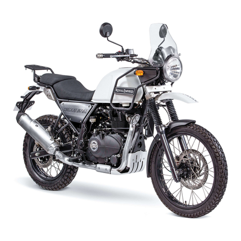
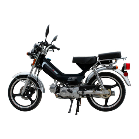
Hanway XRAY125S 2019 User manual

OPERATION MANUAL
XRAY125S
(
4V
)
/STM125
(
4V
)


Preface
1
Preface
Thank you for choosing XRAY125S/STM125S motorcycle. The product
embodies high technology and reliability and incorporates our rich
experiences in manufacturing motorcycles for sports, contests and travel. This
is why the model takes a leading position in the field.
The manual explains the use, operation, basic inspection and
maintenance, etc about the product. If you have any question about the
operation and maintenance, please contact your distributor.
The motorcycle is designed to fully meet the exhaust discharge standards
prevailing on the date of manufacture.
To keep the compliance to the exhaust discharge standards, please carry
out the maintenance schedule and instructions in this manual in cooperation
with your distributor.
The following important information will appear in this manual:
Caution:
Refer to procedures that must be followed. Otherwise, your personal
safety may be endangered.
Notice:
Refer to procedures that must be followed to avoid damaging the
motorcycle.
Warning:
Refer to procedures that must be followed to avoid injury to you, other
person or the motorcycle.
Note:
Refer to some explanations for your better understanding.
Note
This manual should be regarded as part of the motorcycle and should be
always with the motorcycle, even when it is resold.
Warning
Read this manual carefully before driving the light motorcycle
Note
Our company is working hard in improvement of product design and
quality. This manual contains the latest product information at the time
when it is printed. However, it is possible that the manual may be more or
less different with your motorcycle. If you have any question, please
contact your distributor.

Contents
2
Contents
Preface··············································································1
Contents············································································2
Precautions for Safe Riding·················································4
Names of different parts······················································5
The Serial Number······························································ 7
Functions of Controllers····················································· 8
Instrument Panel Indications 8
Ignition switch 11
Switches on the Handlebars 12
Gear Shifting 14
Side Stand 14
Fuel Tank Cap 15
Seat Lock 15
Foot Brake (rear wheel) 16
Fuel and Oil Recommendations···········································17
Break-in of New Motorcycle················································ 18
Inspection before Riding···················································· 20
Inspection the Braking effect and the free play 20
Inspection of the Tire 20
Inspecting the Quantity of Fuel 21
Inspecting the Quantity of Engine Oil 21
Inspection of the Ignition Unit and the Lights 21
Inspecting the Rear Mirror 21
Inspecting the Reflectors and the License Plate 21
Inspecting the Chain Tightness 21
Riding Tips······································································· 22
Start the Engine 22
Start off 22

Contents
3
Inspection and Maintenance··············································· 25
The first maintenance 25
Maintenance Schedule 26
Engine Oil 27
Battery 28
Spark Plug 29
Air Filter 29
Tires 31
Brake circuits 32
Fuel Hose 33
Fuse 33
Troubleshooting································································ 34
Storage Procedures··························································· 35
Specifications··································································· 35
Circuit Diagram································································· 38

Precautions for Safe Riding
4
Precautions for Safe Riding
Please obey local traffic regulations and mind the safety prior to anything. It is
advised to control the speed within safe limits.
Practice before Riding
Before riding the motorcycle in traffic, it is recommended that you practice your
riding at a spacious and traffic-free place so that you are skilled enough to ride safely
and are familiar with the motorcycle's controls. Practice is essential for safety. Please
observe any special training and or government test required before using your
motorcycle on the public highways.
Knowing Your Safety Speed Limit
Safety speed limit varies in accordance with the road conditions, riding skill and
the weather. To know the speed limit is helpful to avoid traffic accidents.
Be Careful in Rainy Days
It is dangerous to ride on the damp or wet road. Therefore, high speed should be
avoided and special care should be taken when turning. Bear this in mind, the braking
distance in rainy days is twice as much as sunny days.
Correct Wearing of Safety Helmet
Wear the safety helmet whenever you ride, and make sure you fasten the strap
securely whenever you wear the helmet.
Safety clothing Recommendation
Bright-colored and well-fitting clothes are recommended. Mind that the clothes
should allow the limbs to move freely.
Clothes of thick materials and shoes with short heels are also recommended.
Indispensable Maintenance and inspection
The following items are indispensable:
Check up before each riding.
Half-year thorough inspection.
One-year thorough serving.
Those listed in Maintenance Schedule.
Care of High Temperature
The high temperature at muffler may cause burn. Please park your motorcycle
where there's little chance of touching.
Flammable materials, such as cotton waste, should not be put near the engine or
the muffler as they might cause fire.
No modification is allowable
Modification to the unit is not allowed and may not guarantee a safe driving.

Names of different parts
5
Names of different parts
Read the following labels carefully before using the motorcycle.
1.Rear lamp
5. Front turning lamps
9. Muffler
2. Rear turning lamps
6. Head lamp
10.Rear brake pedal
3. Seat
7. Front Cushion
11.Air filter
4. Acceleration grip
8. Rear disc brake
①
②
③
④
⑤
⑥
⑦
⑧
⑨
⑩
○
11

Names of different parts
6
1. Speedometer
5. Rear reflector
2. Rear-view mirrors
6. Side stand
3. Left grip switch
7. Shift pedal
4.Side reflector
8. Front disc brake
②
④
③
①
⑤
⑥
⑦
⑧

The Serial Number
7
The Serial Number
Engine number
Engine number is stamped on the side of the crankcase assembly.
Note
Remember your engine number in mind for convenience in purchasing
correct spare parts from your distributor.
Chassis number
Chassis number is stamped on the frame.
Chassis number Engine number
Please write down the serial numbers below for future reference.
Chassis Serial No. :
Engine Serial No. :

Functions of Controllers
8
Functions of Controllers
Instrument Panel Indications
1Coolant indicator lamp
This is use for liquid cooling vehicle. Air cooled vehicle, this place is
empty.
2MI Indicator
If this warning light appears during running please consult your dealer
3Neutral-gear indicator
The indicator indicates no input is loaded. In addition the selected gear
(0) is shown in the LCD-Display.
4Fuel gauge
At the LCD-Display the tank contents is shown with bars. If the tank is
even empty the warning lamp ④in the cockpit lights up.
5Speed display
Display the speed in kilometers per hour (km/h).
6Rev Counter
The rev counter indicates the engine speed in revolutions per minute.
The correspondence between the lattices and engine speed see the
following form.

Functions of Controllers
9
RPM
Lattices
RPM
Lattices
0
0
6400~7000
10
100~1600
1
7100~7700
11
1700~2000
2
7800~8400
12
2100~2400
3
8500~9100
13
2500~2800
4
9200~9800
14
2900~3500
5
9900~10500
15
3600~4200
6
10600~10900
16
4300~4900
7
11000~11300
17
5000~5600
8
11400~11700
18
5700~6300
9
11800~
18+OVER BOOST
7Battery control display
When the battery voltage becomes too low, the control display of the
battery will begin to flash. The symbol will stop flashing as soon as the
voltage rises above the minimum voltage 11.5V.
8Digital clock
In the cockpit there is a digital clock.
9Multifunction display
This display shows several functions. Press and release the button
“M”to change between the information: Total distance counter, distance
counter, average speed and travel time / lap time. The display of the
distance counter, average speed and travel time / lap time can reset by
pressing and holding the button “S”.
*Total distance counter (ODO)
The counter displays the total distance covered by the vehicle in
kilometers or miles.
*Distance counter (TRIP)
The display indicates the distance travelled since the last reset.
Set up:
1.To activate the setup mode, press the button “S” until the time
(hour) begins to flash.
2. Now set the hour even with the button “S” and confirm your
entry with the button “M”.
3. Now set the minutes with the button “S” and confirm with the
Button “M” again.

Functions of Controllers
10
*Average speed (AVE)
This display shows the average speed since the last reset.
*Travel time / lap time (LAP)
This display shows the travel time / lap time since the last reset.
⑨.1 set the diameter of wheel
Display
Press
time
Result
TDO
>3s
enter the setting of wheel
diameter, thousands digit if flash
thousands digit if flash
>3s
hundreds digit is flash
>3s
tens digit is flash
tens digit is flash
>3s
units digit is flash
>3s
enter the speed units setting
any digit is flash
<3s
digit plus 1
⑨.2 set the speed units
Display
Press
time
Result
speed units is flash
>3s
return TDO
speed units is flash
<3s
switch between km/h and mph
⑨.3 time setting
Display
Press
time
Result
TIME
>3s
enter time setting hour-digits is flash
hour-digits is flash
<3s
hour-digits plus 1 between 0~23
hour-digits is flash
>3s
minute-digits is flash
<3s
minute-digits plus 1 between 0~59
minute-digits is flash
>3s
return to TIME
⑨.4 Trip distance, time counting, average speed return to zero
Display
Press
time
Result
TD
>3s
trip distance record return to zero
LAP
>3s
time counting record return to zero
AVE
>3s
average speed return to zero

Functions of Controllers
11
10 Direction indicator
This indicator flashes when the direction indicators are in
operation.
11 Full beam headlight indicator
The indicator lights when the headlight is on full beam.
Ignition switch
Rotate the key to turn power ON or OFF.
ON
The engine can be started
Possible to drive
It is impossible to pull out the key.
OFF
The engine cannot be started.
The engine is stopped
The key can be inserted or pulled out
LOCK
The steering bars can be locked to one direction.
The key can be inserted or pulled out.
When you leave the motorcycle, you may lock the steering handlebars
to prevent your motorcycle from being stolen.
1. Turn the handlebars to the left.
2. Insert the key (if it is not in) from OFF position. Press the key in and
turn it anti-clockwise to LOCK position.
3. Pull out the key.
To unlocking the handlebars, insert the key from LOCK position and
turn it (without pressing) clockwise to OFF position.
Note
Swing the handlebars to check if they are locked.
If it is hard to lock, you may turn the handlebars slightly rightward and
try again.

Functions of Controllers
12
Switches on the Handlebars
①Dimmer Switch
This switch is used to change the headlamp beam. When you turn the
switch to:
HIGH
The high beam is turned on.
LOW
The low beam is turned on.
②Turning Signal Lamp Switch
This switch is used to turn on/off the left/right turning signal lamps to
show the other vehicles that you want to turn leftward/rightward. When you
turn the lever to:
Right
The right signal lamps flash.
Left
The left signal lamps flash.
Center
Push in the switch at the center position to
cancel the turn-signal operation.
①
②
③
④
⑤

Functions of Controllers
13
Please do turn off the lamps when they are no longer necessary,
otherwise you may cause trouble to people in front of or behind you.
③Horn Button
Press this button to sound the horn.
④High Beam Flash Button
Press this button to light the high beam temporarily.
⑤Clutch Lever
Grip this lever to disengage the driving system at the time of starting
the engine or shifting the gear. Disengage the clutch by grasping the lever.
⑥Stop Switch of Engine
This switch, located on the top of the control panel of the right
handlebar, is of swinging plate type. Its shaft is placed on the center of the
plate. When it is on the “ ” position, the engine can be started.
If the switch is on the “ ” position, the short circuit will be formed
for ignition coil, so the engine cannot be started.
⑦Starter Button
This button is used to start the engine. Turn the ignition key to ON,
squeeze the rear brake lever and press the button, the engine will be started
immediately.
⑧Brake Levers
By operating the brake levers ⑧, you can control the speed of the
motorcycle and even make it stop. The brake is applied by squeezing the
brake lever gently towards the grip. The brake light will be lit when the
lever is squeezed inward.
⑨Throttle Grip
⑥
⑦
⑧
⑨

Functions of Controllers
14
Throttle grip ⑨is used to control engine speed. Turn it towards you
to increase engine speed; Turn it away from you to decrease the engine
speed.
Gear Shifting
This model of motorcycle is equipped with a five-shift gear-in
transmission system. The working order of the gearshift is as shown in the
fig.
The lever is connected to the ratchet of the gearshift. It will return
automatically to its original position after selection of a certain gear so that
it is possible to change to the next gear. The neutral gear is located between
the bottom and second gears. In the neutral mode, press the lever and the
low gear will be engaged, each time the lever is shifted up, a higher gear is
engaged. With the Ratchet mechanism, only one upper or lower gear is
engaged each time. When you shift the gear from the low position to the
second position or from the second position to the low position, slide over
the neutral position without stop. If the neutral gear is desired, stop
between the bow gear and the second gear, thus getting in the neutral gear.
Side Stand
To use the main, depress it by foot and lift the rear of the motorcycle
until the rear wheel is lift. To use the side, depress the end of it until it
rotates to the end and stops.

Functions of Controllers
15
Fuel Tank Cap
The fuel tank cap is provided with a latch.
To open it:
1. Lift the protection plate of the latch.
2. Keep the tap in the locked position, turn the latch to the left side and
then, remove the cap.
Warning
The sealed lock can increase slightly the pressure in the tank, and so, it is normal
that you hear a noise produced by the air when it comes out.
To close it:
1. Insert the cap with the key;
2. Turn the key to the right side and remove it.
Seat Lock
To open and close the seat as follows:
1. The seat lock lever is under the seat, press the seat and pull the seat
lock lever outside, then, lift the seat. The seat will be opened.
2. Push the seat gently and it will be locked automatically. Lift the seat
gently to check if it is locked.

Functions of Controllers
16
Foot Brake (rear wheel)
The foot brake pedal is on the right hand side of the engine.
You operate the rear wheel brake by pressing down the foot brake
lever lightly with your foot.

Fuel and Oil Recommendations
17
Fuel and Oil Recommendations
Fuel
Use unleaded gasoline with an octane number E5 or higher. Unleaded
gasoline can extend spark plug life and exhaust component life.
Engine Oil
Use of high quality 4-stroke engine oil would extend the lifetime of
the engine. Grade SE or SD engine oil in API method is recommended,
whose viscosity is SAE10W-40. If this oil is not available, please purchase
appropriate substitutes according to the data listed below.
Transmission Oil
Use good quality SAE 10W-40 multi-grade motor oil.
This manual suits for next models
1
Table of contents