Hanyang Navicom RFCT-10 User manual

RFCT-10 manual
Transmitter for wireless clock system

Contents
1 Description.................................................................................................................... 1
2 Initial Setup ................................................................................................................... 4
2.1 Preparation for setup.......................................................................................... 4
2.2 Setup ...................................................................................................................4
3 Operation ...................................................................................................................... 6
3.1 Operation details.................................................................................................6
3.2 GPS Operation.....................................................................................................8
3.3 SNTP Operation ..................................................................................................9
4 Monitoring using PC ...................................................................................................10
4.1 Preparation........................................................................................................10
4.2 Command...........................................................................................................11
5 LCD Menu using key pad............................................................................................17
5.1 Status ................................................................................................................17
5.2 Time ..................................................................................................................17
5.3 Reference.......................................................................................................... 18
5.4 Radio Frequency ...............................................................................................19
5.5 Init LCD .............................................................................................................20

FCC CONCERNS
FCC Compliance Statement
This equipment has been tested and found to comply with the limits for a Class A digital device,
pursuant to part 15 of the FCC Rules. These limits are designed to provide reasonable protection
against harmful interference in a residential installation.
This equipment generates, uses and can radiate radio frequency energy and, if not installed and used in
accordance with the instructions, may cause harmful interference to radio communications. However,
there is no guarantee that interference will not occur in a particular installation. If this equipment does
cause harmful interference to radio or television reception, which can be determined by turning the
equipment off and on, the user is encouraged to try to correct the interference by one or more of the
following measures:
- Reorient or relocate the receiving antenna.
- Increase the separation between the equipment and receiver.
- Connect the equipment into an outlet on a circuit different from that to which the receiver
is connected.
- Consult the dealer or an experienced radio/TV technician for help.
RF Exposure Statement:
The antenna(s) used for this device must be installed to provide a separation distance of
at least 20 cm from all persons and must not be co-located or operating in conjunction
with any other antenna or transmitter.
Do not
Any changes or modifications to the equipment not expressly approved by
the party responsible for compliance could void user’s authority to operate
the equipment.

1
1Description
Figure 1.1
The RFCT-10 receives a time from a GPS (global positioning system)
receiver or from a NTP (network time protocol) server via ethernet port.
Then the RFCT-10(time transmitter) broadcasts the time to remote wireless
clocks (time receiver of our company). As a result, all the wireless clocks are
synchronized to the exact time. This time synchronization system is ideal for
schools, universities, hospitals, and other applications in synchronizing time.
Ethernet
Transmitter
RFCT-10
GPS Satellite
Wireless
Clock
GPS
Receiver
Figure 1.2
Input, output and in-out ports are described as follows.
-Input port
¾DC Power ( 9VDC )
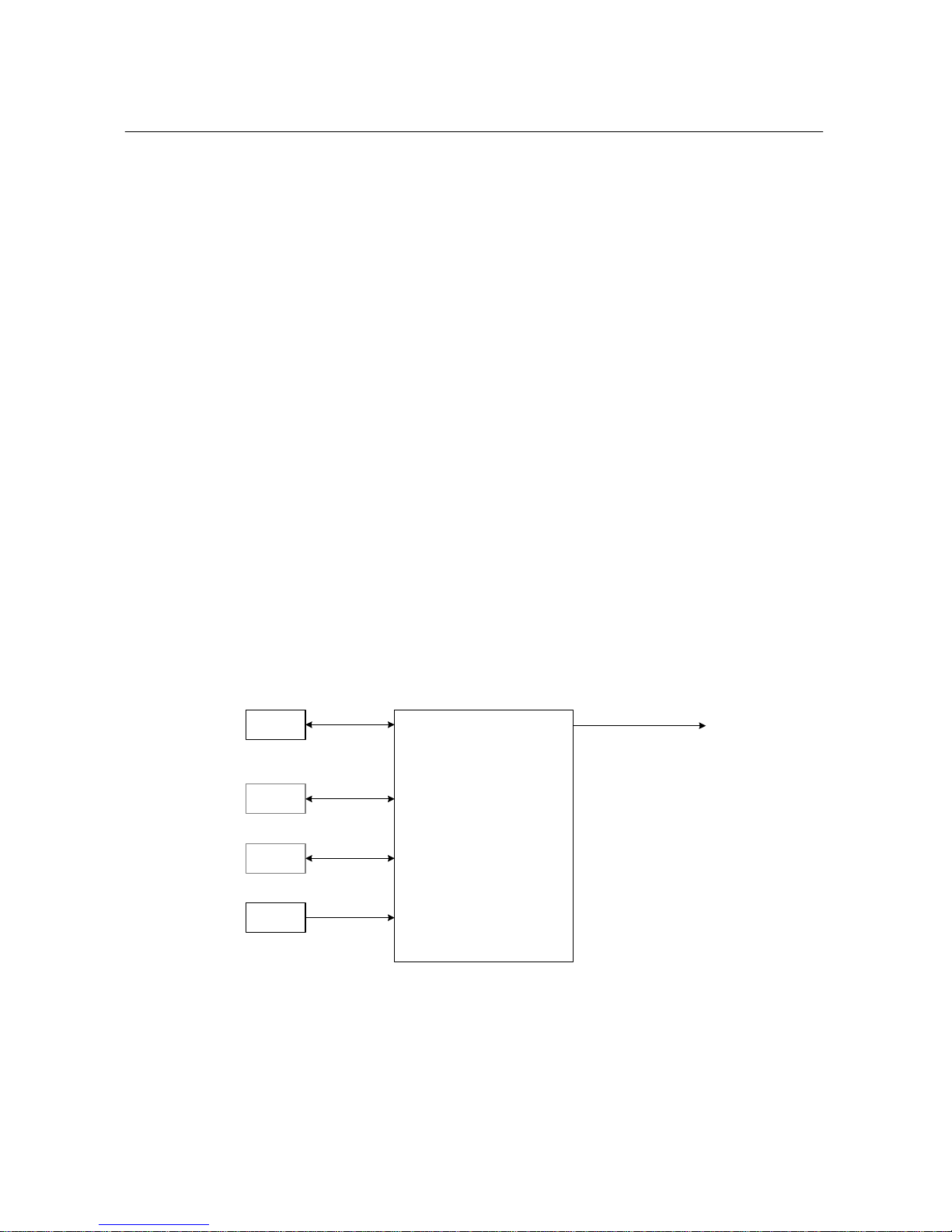
2
¾GPS Antenna port
¾Key pad( 4x4 array)
-Output port
¾RF Antenna port
-Input and output port
¾RJ-45 RS232 PC Interface port
¾Ethernet port
-Display output
¾LED( REF, Alarm, Fault, PWR)
¾LCD
-Accessory
¾AC-DC Adaptor ( input:100-240VAC, output:9VDC/1.5A)
¾GPS Antenna(GPS18LVC)
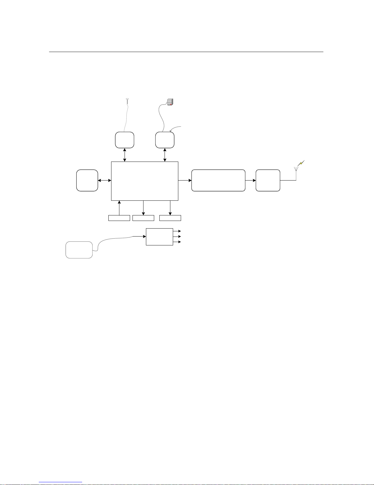
Figure 1.3 shows the input, output and in-output connection.
RFCT(Transmitter)
GPS
Ant.
NTP
Server
RS232
Ethernet
PC RS232
AC/DC
Adaptor
Input:110~220V AC
Output: 9V DC
FM
72.1MHz~72.4MHz
30dBm(1W max.)
*Monitor port connector only
when being monitored.
GPS port
Ethernet
port
Monitor
Port
Figure 1.2
3
Figure 1.4 shows the block diagram of RFCT-10
Processor block
(uController+
Flash memory+SRAM)
72MHz Narrow Band FM
Modulator Power
Amplifier
GPS
Receiver
Port
Ethernet
Port
LCD LED
PC
Monitor
port
for connecting network time server(NTP) Server
DC-DC
Block
5V
3.3V
7V
Keypads
ethernet
RS232
RS232
TTL TTL TTL
NTP Server
internet
GPS Antenna
Data 72MHz
110/220V –9VDC
AC-DC
Adaptor
9V
Figure 1.4

4
2Initial Setup
2.1 Preparation for setup
zRFCT-10 Set
¾Transmitter (RFCT-10 main body).
¾AC-DC Adaptor power supply
¾RF Transmitter Antenna
¾GPS Antenna
zPC and monitoring cable( refer to 4.Monitoring using PC) : optional
2.2 Setup
2.2.1 Location
The first step in setting up the transmitter is to determine a suitable location for
the transmitter and GPS unit. The transmitter's power supply requires 120 Volts
AC so proximity within reach of the transformer cord is needed. It is
recommended that the transmitter be located a minimum of 2 to 3 feet above
the floor and away from large metal objects, such as lockers, filing cabinets,
etc. The transmitted signal from the antenna radiates in a circular and
‘umbrella ’ pattern, therefore the coverage for an area will be better if the
transmitter is centrally located. In multistory buildings, locating the transmitter
on the top floor will often significantly improve coverage for the lower floors
due to the umbrella ’ pattern of transmission.
The GPS antenna needs a clear view of the sky to receive the GPS signal. Only
the cable permanently attached to the GPS unit may be used outdoors. then
additional cable is required the connection must be sealed with Radio Shack
coaxial Cable Connector Sealant 278-1645 or high quality silicone sealant to
weatherproof the connection. Any cable extensions must be protected from
outside elements.
2.2.2 Assembly of the RFCT-10
1. Carefully screw the transmitter antenna onto the transmitter. The antenna
must be snug against the case but hand-tighten only.
2. Plug the GPS unit cable into the transmitter.
3. Attach the GPS unit to the inside of a window
4. Plug the supplied 9-volt/1.5 Amp DC power supply into the transmitter.
5. Plug in the supplied 9-volt/1.5 Ampere DC power supply into a 120 VAC
outlet.
6. Set all the parameter on the transmitter using key pad.

5
7. RFCT-10 setup is complete

6
3Operation
When Power is first applied to the transmitter the time is set to 00:00:00. Then the
transmitter reads configuration parameters, user adjustable via key pad, from the
internal flash memory. The transmitter then sends information to the GPS unit and
waits for time information from the GPS unit. Depending on the location, weather
conditions, time of day, etc. this can require up to several minutes for the initial
time verification. Once the transmitter has received the GPS unit signal for time,
the transmitter sets its internal clock to that time. The transmitter then starts to
transmit its internal time once every second. The transmission signal are depends
on one-watt FM signal at approximately 72.2 MHz. The transmitter continually
monitors the GPS unit and the transmitter’s internal clock is updated every time the
transmitter received data from the GPS unit.
3.1 Operation details
3.1.1 Start up
After initial power up, LEDs (REF, Alarm, and Fault) will go off, and LCD will
display as below. The simplest way to be sure transmitter is running properly
is to see if the time on LCD increases per second.
1.Status, GPS:N/A, Channel:#0
2006,Jan-01,00:00:00,Sun, DLS:OFF
3.1.2 Reference setup
Change the reference type from the default “GPS” to desired reference.
Move, first, to the screen “3.Reference.” followed by pushing “Enter” button.
Then, keep pushing the “Menu” button until you see “3-5. Reference
Source” screen.
3-5.Reference Source <GPS:1 SNTP:2>
[GPS]
① Key in “1” for NTP, and “2” for SNTP followed by pushing “Enter”
button.

7
3.1.3 Local time setup
By default, system time is set to UTC, and the offset from UTC is set to 0.
To get the correct local time, appropriate local time offset needs to be set.
Move, first, to the screen “2.Time.”
2.Time, 2006,Oct-26,02:39:12, Thu
Local Offset: 0hr. 0min. DLS:ON
① Push “Enter” button.
2-1.Local Hour <Sing:* Backspace:#>
[Hour: 0] 9
② Type in local hour offset followed by pushing “Enter” button.
③ Push “Menu” button.
2-2.Local Min <Sing:* Backspace:#>
[Min: 0]
④ Type in local minute offset followed by pushing “Enter” button.
3.1.4 Daylight Saving Setup
Move, first, to the screen “2.Time.” followed by pushing “Enter” button.
Then, keep pushing the “Menu” button until you see “2-3.Daylight saving”
screen.
2-3.Daylight Saving <Dot:* Backspace:#>
[Start(m.d.h): 4.2.2]
① Type in start date of Daylight Saving followed by pushing “Enter”
button.
② Push “Menu” button.
2-4.Daylight Saving <Dot:* Backspace:#>
[End(m.d.h): 10.29.2]
③ Type in end date of Daylight Saving followed by pushing “Enter”
button.

8
3.1.5 RF Channel Setup
Setup the desired RF channel out of 16 channels. Move, first, to the
“4.Radio Frequency” screen. Then push the “Enter” button.
4.Radio Frequency, ON
Channel:#0, Attenuator:#0
① Push “Enter” button.
4-1.Channel <Backspace:# Range:0->15>
[Channel: 0]
② Type in desired channel followed by pushing “Enter” button.
3.1.6 RF Attenuator Setup
Move, first, to the “4.Radio Frequency” screen followed by pushing “Enter”
button. Then, keep pushing the “Menu” button until you see “4-
2.Attenuator” screen.
4-2.Attenuator <Backspace:# Range:0->31>
[Attenuator: 0]
① Type in desired attenuator value followed by pushing “Enter” button.
3.2 GPS Operation
3.2.1 Confirm the GPS Receiver Operation
Current GPS status information including positioning mode, number of
satellites in tracking, DOP (Dilution of Precision), and leap second is
available on the “3. References” screen. More details available via the
Monitor port. REF(green) LED indicates the reference is in good health and
transmitter is ready for RF transmission.
3.Reference, GPS, 3D-Fix
Sat: 5/11, DOP:1, LS:14s

9
3.3 SNTP Operation
Not available for the time being.
10
4Monitoring using PC
4.1 Preparation
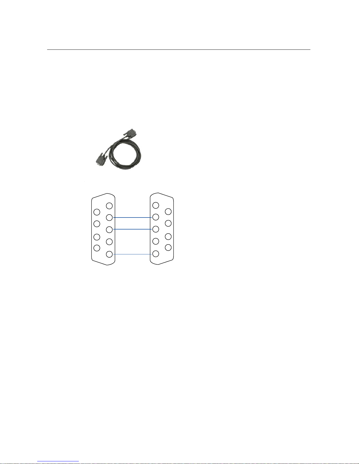
4.1.1 Serial Cable
1
2
3
4
5
6
7
8
9
Tx
Rx
GND
Tx
Rx
GND
RFCT-10 PC
1
2
3
4
5
6
7
8
9
4.1.2 Connection
① Connect the serial cable from the COM port of your computer
② Connect the other end of cable to the “MONITOR PORT” on the rear
of the transmitter
③ Start a Hyper terminal session, or any other terminal program in
your favor, on COM port with the following settings
Bits per second = 115200
Data bits = 8
Parity = None
Stop bits = 1
Flow control = None

11
4.2 Command
HELP
- Displays command list and description.
Example)
Oct-26 23:56:37,1> help
PS
- Displays process status.
• Oct-26 2:47:9: Local time
• Tasks: Current number of tasks running
• CPU Usage
• Running Time: Running time since the last power-on.
Example)
Oct-26 23:56:37,1> ps
…
Oct-26 23:56:37,1> ^C

12
DATE
- Displays UTC and Local time.
• UTC (GMT): Universal Time Coordinated
• Local: The time the differential factors such as local time offset and daylight saving are
applied to UTC.
Example)
Oct-26 23:56:37,1> date
ANT
- Displays NMEA input from GPS Receiver.
• 02:114>: Received second, millisecond.
• NMEA: NMEA information
Example)
Oct-26 23:56:37,1> ant
…
Oct-26 23:56:37,1> ^C
13
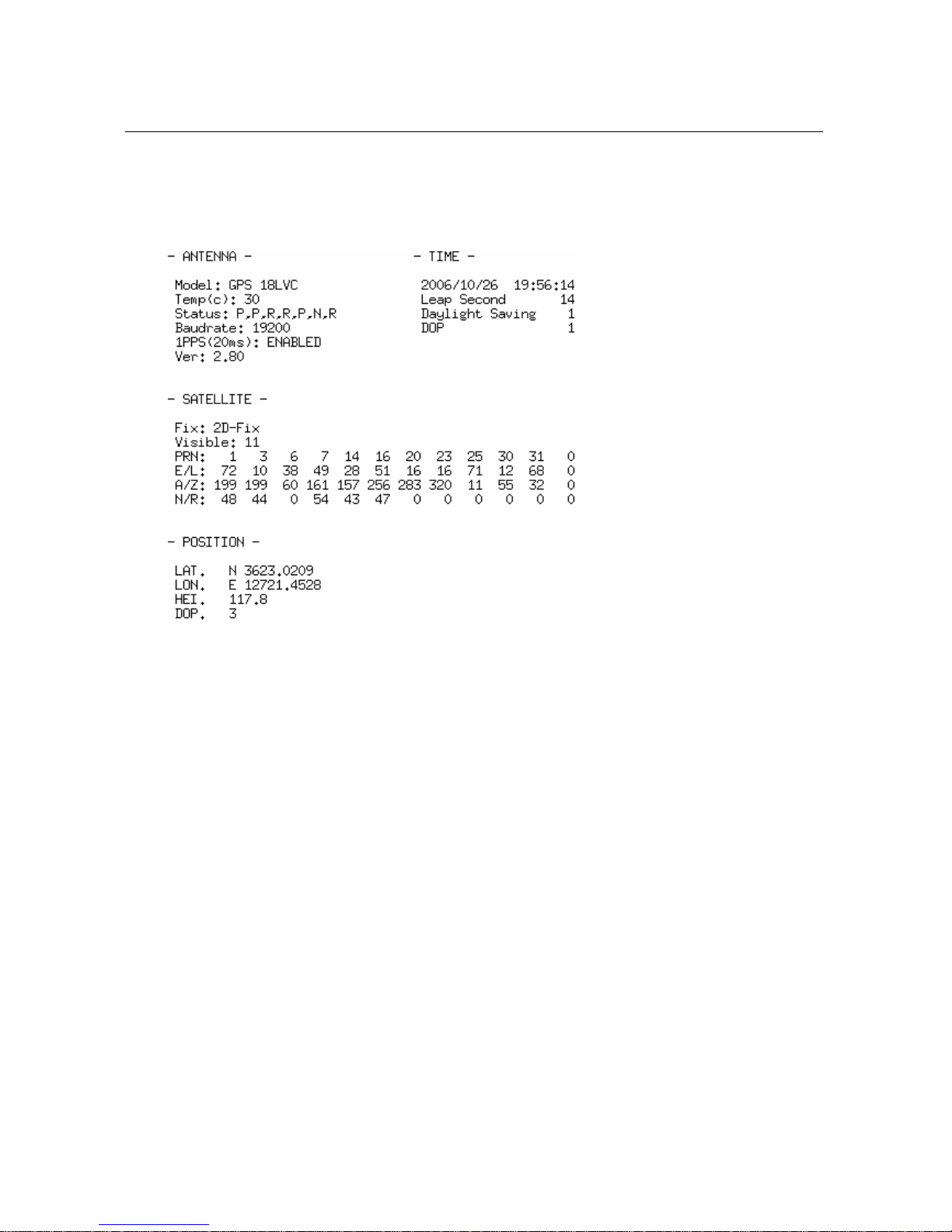
GPS
- Displays GPS Status
• Antenna: GPS Receiver information
▪ Model: Model name
▪ Temp: Temperature
▪ Status: Self-test result (P=Pass, F=Fail, R=Retained, L=Lost, N=Null)
-ROM checksum test(P,F)
-Receiver failure discrete(P,F)
-Stored data lost(R,L)
-Real time clock lost(R,L)
-Oscillator drift discrete(P,F)
-Data collection discrete(C, N)
-GPS sensor configuration data(R,L)
▪ Baudrate
▪ 1PPS: 1PPS enable status(pulse width)
▪ Ver: software version.
• Time: Local Time Information
▪ Time: Year/Month/Day Hour:Minute:Second

14
▪ Leap Second
▪ Daylight saving: +/- Daylight saving offset
▪ DOP: Dilution of Precision(Time)
• Satellite: Satellite tracking information
▪ Fix: Current positioning mode
▪ Visible: Number of satellites in view
▪ PRN: Satellite ID number
▪ E/L: Elevation
▪ A/Z: Azimuth
▪ N/R: Noise Ratio
• Position: Position information
▪ Lat: Latitude
▪ Lon: Longitude
▪ HEI: Height
▪ DOP: Dilution of Precision(Position)
Example)
Oct-26 23:56:37,1> gps
…
Oct-26 23:56:37,1> ^C
SNTP
- Displays SNTP status
Example)
Oct-26 23:56:37,1> sntp
…
Oct-26 23:56:37,1> ^C
15
PPS
- Displays 1PPS input
Example)
Oct-26 23:56:37,1> pps
…
Oct-26 23:56:37,1> ^C
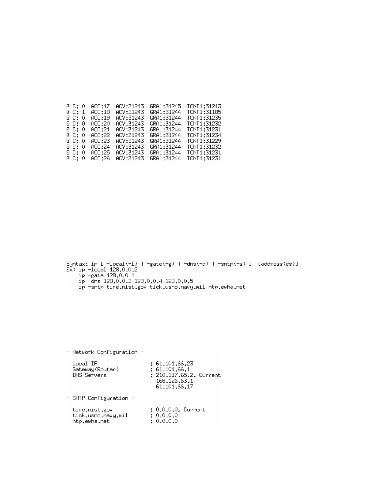
IP
- Setup and displays IP addresses
NET
- Current Network status

16
Example)
Oct-26 23:56:37,1> net
RST
- Reboot system
Example)
Oct-26 23:56:37,1> rst
System Soft Reset……
Oct-26 23:56:37,1> rst –c
System Config Reset……
^C
- Abort Current Command
^Z, ^X
- Command History

17
5LCD Menu using key pad
5.1 Status
- Displays current status of RFCT-10
1.Status, GPS:3D-Fix, Channel:#0
2006,Oct-26,02:39:12,Thu, DLS:ON
5.2 Time
- Displays time related settings of RFCT-10
2.Time, 2006,Oct-26,02:39:12, Thu
Local Offset: -6hr. -45min. DLS:ON
Table of contents
Popular Transmitter manuals by other brands


Air Comm Systems
Air Comm Systems Six Passenger ICS/Transmit Expansion Unit ACS... Installation and operation manual

Viking
Viking C-210 Technical practice

FISCHER
FISCHER DE61 instruction manual

Voxoa
Voxoa Btunes user manual

SpiderAlert
SpiderAlert MDT-122 S user guide

GLI International
GLI International PRO-series operating manual


