PRO-series Model E3 Electrodeless Conductivity Transmitter
5
CONDENSED OPERATING INSTRUCTIONS
This manual contains details for all operating aspects of the instrument. The following condensed in-
structions are provided to assist you in getting the instrument started up and operating as quickly as
possible. These condensed instructions only pertain to basic conductivity measurement opera-
tion. To measure % concentration or TDS, or to use specific features of the instrument, refer to the
appropriate sections in this manual for instructions.
A. CONNECTING SENSOR/CONFIGURING TEMPERATURE ELEMENT TYPE
1. After properly mounting the transmitter (PART TWO, Section 2), connect the GLI electrodeless
conductivity sensor, matching wire colors to terminals as indicated:
Sensor Wire Colors Connect To TB2
White Terminal 1
Blue Terminal 2
#LEARTerminal 3
"LACKTerminal
2EDTerminal
9ELLOW Terminal
Terminal UNUSED
'REEN4ERMINAL
2. The transmitter is factory-set for automatic temperature compensation using the Pt 1000 ohm tem-
perature element built into GLI electrodeless conductivity sensors. If you want fixed MANUAL
temperature compensation, change the temperature element type to “MANUAL” and enter a tem-
perature. For details, see PART THREE, Section 3.2, subheading “Select TEMP ELEMENT Type.”
B. CONNECTING DC POWER
Refer to PART TWO, Section 3.2, 3.3, 3.4, or 3.5 to connect DC power to the transmitter.
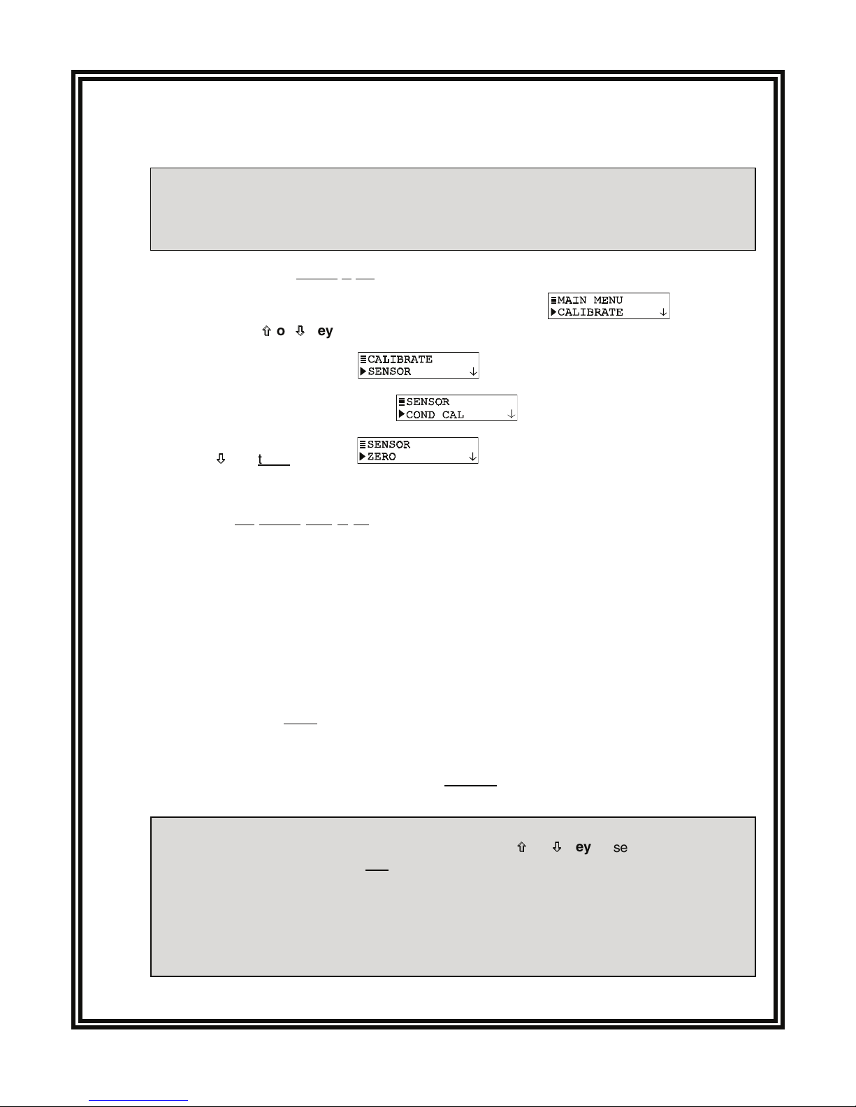
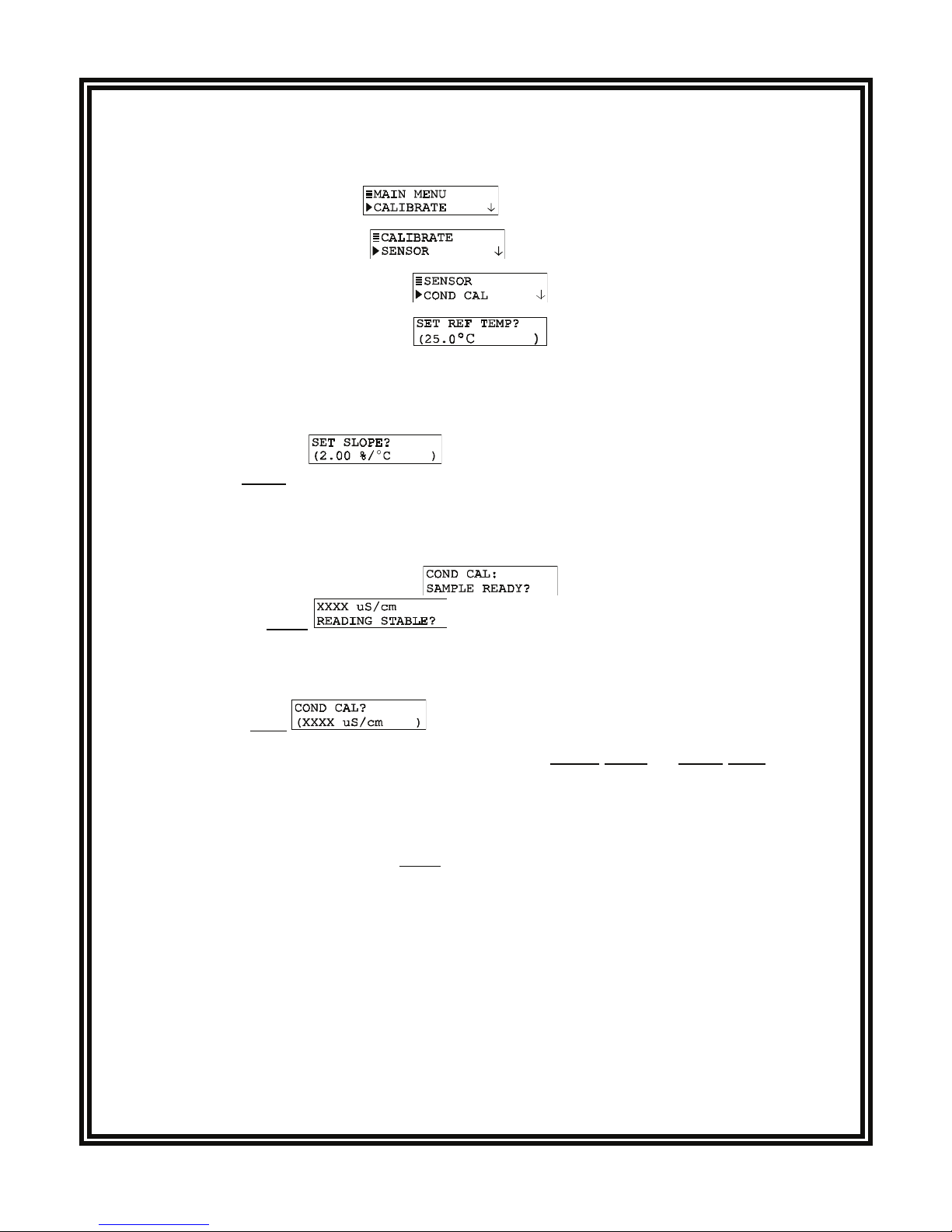
C. CALIBRATING THE TRANSMITTER
The transmitter must be calibrated so that measured values will correspond to actual process values.
Preferably, use the “COND CAL” calibration method to enter the known value of a properly prepared
conductivity reference solution. (To calibrate with a sample of the process, use the “SAMPLE CAL”
method to enter its known value determined by laboratory analysis or a comparison reading.)
Calibration Tip! Each electrodeless conductivity sensor has a unique zero point and span. Conse-
quently, when calibrating a sensor for the first time, always zero it according to step 1. Zeroing
provides the best possible measuring accuracy.
NOTE: An in-progress calibration can always be aborted by pressing the ESC key. After the
“ABORT: YES?” screen appears, do one of the following:
•
Press ENTER key to abort. After the “CONFIRM ACTIVE?” screen appears, press ENTER
key again to return the analog output to its active state (MEASURE screen appears).
•
Use
×
×
or
Ø
Ø
key to choose “ABORT: NO?” screen, and press ENTER key to continue calibration.
1. Zero the sensor if it is being calibrated for the first time. If not, disregard this step and perform
steps 2 through 13.
Zeroing Tip! If the “ZERO: CONFIRM FAILURE?” screen appears at any time during zeroing,
press ENTER key to confirm. Then, use the
×
×
or
Ø
Ø
key to select between “CAL: EXIT” or
“CAL: REPEAT” and do one of the following:
(continued on next page)