Kenco KT Series User manual

Modbus Interface Manual
“KT” Series Magnetostrictive
Liquid Level Transmitters
Kenco Engineering Company
10001 East 54th Street
Tulsa, Oklahoma 74146
Phone: 918-663-4406
Fax: 918-663-4480
Website: www.kenco-eng.com
Email: [email protected]
79863
(Rev. #)
[5-2-19]

2
Modbus Interface Manual
Table of contents
.................................................................3
2. .................................................................................5
......................................................................5
4. ..................................................................5
4.1 Before You Begin ...................................................................5
4.2 Quick Start-Up Procedure ..................................................... 5
5. ..............................................................................5
5.1 Operation Modes................................................................... 5
5.1.1 Run Mode ...................................................................... 5
5.1.2 Program Mode............................................................... 5
5.2 Display Diagram.................................................................... 6
5.3 Menu Structure......................................................................6
6. Alarms.........................................................................................6
7. Error Codes (Faults)....................................................................7
8. ........................................................................7
8.1 Dashboard ............................................................................ 8
8.1.1 Installing Dashboard...................................................... 8
8.1.2 Home Screen ................................................................. 8
8.1.3 ................................................................. 9
8.1.4 Signal Settings.............................................................. 9
8.1.5 Level Settings ............................................................... 9
8.1.6 Temperature Settings.................................................. 10
8.1.7 Volume Settings.......................................................... 11
8.1.8 Flash Settings ............................................................. 11
8.1.9 Save Settings .............................................................. 12
8.2 Programming the Display ................................................... 12
8.3 Modbus Function Codes ..................................................... 13
8.4 Modbus Register Maps....................................................... 15
8.5 How Units are Used ............................................................ 19
8.6 Modbus Register Map Notes .............................................. 19
8.7 Formulas Used in Volume Calculation................................. 21

3
Modbus Interface Manual
‘Generalized Crude Oils’, Correction of Volume to 60 °F against API
Gravity.
‘Generalized Products’, Correction of Volume to
60 °F against API Gravity.
‘Volume Correction Factors (VCF)’ for individual and special applica-
-
cients.
A
The measure of how heavy or light a petroleum liquid is compared to
water. Allowable values are 0 to 100 degrees API for (6A) and 0 to 85
degrees API for (6B).
D
DDA
‘Direct Digital Access’ – The digital protocol for use in intrinsically safe
areas.
density value should be entered as lb / cu. ft..
E
Type of protection based on enclosure in which the parts which can
ignite an explosive gas atmosphere are placed within, and which can
withstand the pressure developed during an internal explosion of an ex-
plosive mixture, and which prevents the transmission of the explosion
to the explosive gas atmosphere surrounding the enclosure.
F
Type of protection based on enclosure in which the parts which can
ignite an explosive gas atmosphere are placed within and which can
withstand the pressure developed during an internal explosion of an ex-
plosive mixture, and which prevents the transmission of the explosion
to the explosive gas atmosphere surrounding the enclosure.
An all digital, serial, two-way communications system that serves as
the base-level network in a plant or factory automation environment.
‘Gross Observed Volume of the Interface’ – The total volume of the tank
occupied by the interface liquid. The GOVI is only given when mea-
suring two liquids and is calculated by subtracting the volume of the
product from the total volume of liquid in the tank (GOVT – GOVP).
‘Gross Observed Volume of the Product’ – The total volume of the tank
occupied by the product liquid. When measuring only one liquid, it is
also the total volume of liquid in the tank (GOVT). When measuring two
liquids it is the total volume of liquid in the tank minus the volume of
the interface liquid (GOVT – GOVI).
‘Total Gross Observed Volume’ – The total volume of liquid in the tank.
When measuring only one liquid it is equal to the volume of the product
(GOVP). When measuring two liquids it is equal to the volume of the
product and interface liquids (GOVP + GOVI).
‘Gross Observed Volume Ullage’ – the difference in volume between the
working capacity of a tank and the total volume in the tank (Working
Capacity – GOVT).
H
HART®
A Bidirectional communication protocol that provides data access
I
Interface
Noun; The measurement of the level of one liquid when that liquid is
below another liquid.
Interface
Adj.; The Software Graphical User Interface (GUI) that allows the user
to access software protocols (HART, DDA, MODBUS).
‘Intrinsically safe’ - Type of protection based on the restriction of
electrical energy within apparatus of interconnecting wiring exposed to
potentially explosive atmosphere to a level below that which can cause
ignition by either sparking or heating effects.

4
Modbus Interface Manual
The property of a body that causes it to have weight in a gravitational
the volume correction factor (Density * VCF).
A serial communications protocol published by Modicon in 1979 for use
with its programmable logic controllers (PLCs). It has become a de fac-
to standard communications protocol in industry, and is now the most
commonly available means of connecting industrial electronic devices.
A product Enclosure intended for indoor or outdoor use primarily to
provide a degree of protection against corrosion, windblown dust and
rain, splashing water, and hose-directed water; and to be undamaged by
the formation of ice on the enclosure. They are not intended to provide
protection against conditions such as internal condensation or internal
icing.
U.S. standard
‘Net Standard Volume of the Product’ – The temperature corrected
volume for the product liquid in the tank, requires the transmitter to
be ordered with temperature measurement capabilities. The NSVP is
calculated by multiplying the volume of the product liquid by a volume
correction factor based on temperature (GOVP * VCF).
R
The temperature at which the density measurement is given, the allow-
able values are 32 °F to 150 °F (0 °C to 66 °C).
S
The density ratio of a liquid to the density of water at the same condi-
tions.
The internal radius of the sphere that contains the liquid, the value is
used to calculate the volume along with the Sphere Offset.
An offset value that accounts for additional volume in a sphere from
non-uniform sphere geometry, the value is used to calculate the volume
along with the Sphere Radius.
A table of measurement correlating the height of a vessel to the volume
that is contained at that height. The transmitter can contain up to 100
points.
T
TEC
-
perature for an object with the change in its volume. Allowable values
are 270.0 to 930.0. TEC units are in 10 E-6/Deg F.
product correction methods used to correct the product
volume in the tank due to changes in temperature from 60 °F including
(6A, 6B, 6C, 6C Mod, and Custom Table.
One of two methods use to calculate volume measurements from level
measurements, including Sphere and Strap Table.
‘Volume Correction Factor’ – A table of measurements correlating
temperature points with correction factors for the liquids expansion/
contraction. The transmitter can contain up to 50 points.
W
The maximum volume of liquid that the user desires for their vessel to

5
Modbus Interface Manual
The content of this technical documentation and of its various
annexes is intended to provide information on mounting, installation
IEC 60079-14 and/or factory trained service technicians and local
regulations.
Warnings are intended for your personal safety and for avoidance
of damage to the described product or connected devices. In this
documentation, safety information and warnings to avoid dangers that
might affect the life and health of personnel or cause material damage
3.1 Intended use
The purpose of this document is to provide detailed information on
the protocol interface. All safety related information is in the product
connecting to the level transmitter.
You must use a RS-485 converter with “Send Data Control” and the
Set-up Software to ensure proper operation.
Example:
RS-485 to USB
1. Connect +24 Vdc to terminals.
2. Connect data lines to terminals.
3. Connect the PC (or other device) to data lines.
(If you are using a PC, use a RS-485 to USB converter. See
Note above for more information.)
4. Turn on power to the transmitter.
5. Start the Dashboard. Select Com Port and Address. Factory
default address is ‘247 ’ for Modbus.
Before starting the operation of the equipment read this documentation
thoroughly and follow the safety information.
Symbol
NOTICE This symbol is used to point to situations
that may lead to material damage and/or personal
injury.
6. Change the address to one that is suitable for the installation
network.
7.
temperature.
8. Turn off power to the transmitter.
9. Remove data lines.
10. Install the transmitter into the vessel (see Operation Manual).
11. Reconnect power and data lines.
12. Calibrate current tank level using setup software (optional).
13. Verify communications with the host system.
All liquid level transmitters are shipped with a Stylus (Kenco Part #
79857) to be used for manipulating the display. For single and dual
cavity housings, the Stylus is designed to allow for programming of the
unit without removing the housing. When using the Stylus make sure
to align the Stylus with the shape outline around the buttons in the same
orientation. Failure to correctly align the Stylus can cause the display to
not function properly.
Do not use any device other than the Stylus to operate the display.
Improper use of the Stylus can cause the display to not function
properly.
The level transmitter runs in one of the following modes of operation.
You can use these modes to calibrate and set up various operating
parameters.
Run mode is the primary mode of operation. This mode will perform
measurements, display data, and respond to Modbus commands.
Program mode is the primary mode for commissioning and trouble-
shooting the level transmitter. The full menu and available functions are
shown in section 5.3 Menu Structure. To enter program mode use the
Stylus and press the Enter Key as shown in section 5.2 Display Diagram.
Program Mode is protected by a password to keep unwarranted chan-
ges from occurring. The factory default password is 27513. When in
program mode, remote communications are not functional. An automa-
tic timeout feature is provided so that the transmitter does not remain
inadvertently in program mode. The timeout is set for 1 minute before
prompted for additional time. Total timeout is 2 minutes.
Modbus: 4800 BAUD 8, N, 1 8 Data bits, No Parity, 1 Stop bit

6
Modbus Interface Manual
Whenever program mode is exited from the display the unit will reset
itself to insure all changes have been accepted. The reset will take
approximately 5 seconds before the level transmitter is able to respond
to commands.
In program mode, the transmitter will not respond to incoming
Modbus commands. A busy error will be sent to the controller to
notify the unit is in program mode. This function will prevent a user at
a remote terminal from programming the unit while a user is accessing
program mode from the display.
– Used to move cursor on screen up and to increment num-
ber.
– Used to move cursor on screen down and to decrease
number.
– Used to move cursor on screen to the right, cursor will
cycle back.
– Used to Enter Program Mode, select Highlighted Item, and
– Hidden key in the middle of the display that is used to exit
menu at any time.
– The process variable that is selected to display.
The display will automatically scroll between selected variables.
– The numerical value for the MEASURED VARIABLE
shown on the display.
– Unit of measurement for the MEASURED VARIABLE shown on
the display.
– Average temperature for the product in the tank. Only
shown if the level transmitter was purchased with temperature.
– Four squares with letters. Top left square will always
be present indicating a D for DDA mode or a M for Modbus mode. Top
right square, A, will only show when there is an alarm. Toggle the
UP Arrow key to view alarms. Bottom right square, F, will only show
when there is a fault. Toggle the DOWN Arrow key to view error codes.
Bottom left square, P, will only show when the unit is being programmed
remotely.
• Data From Device
Display
Units
`Length Units
`Temp Units
`Volume Units
Address
Signal Strength
`Prod Trig Lvl
`Int Trig Lvl
`Roof Trig Lvl
• Calibrate
Product Level
`Current Level
`Offset
Interface Level
`Current Level
`Offset
Roof Level
`Current Level
`Offset
• Factory
Settings
`Gradient
`Serial Number
`HW Revision
`SW Revision
`SARA Blanking
`Magnet Blanking
`Gain
`Min Trig Level
Temp Setup
Auto Threshold
Baud Rate
Volume
Reset to Factory
6. Alarms
The Modbus output is equipped with several alarms that will be shown
on the display. Use the stylus to tap the Up arrow to view alarms. The
Modbus output is set to fail high, greater than the order length, if there
is an issue and the level value output cannot be trusted.
Fig. 1: Modbus Display

7
Modbus Interface Manual
Fault
Code
101 Missing
Magnet
• Verify Float(s) are not in inactive zone.
• Verify Auto Threshold is enabled.
• Cycle power to sensor. If proper operation
is not restored, Contact Factory.
102 Internal
Fault 1
Cycle power to sensor. If proper operation
is not restored, Contact Factory.
103 Internal
Fault 2
Cycle power to sensor. If proper operation
is not restored, Contact Factory.
104 Internal
Fault 3
Cycle power to sensor. If proper operation
is not restored, Contact Factory.
105 Lobe Fault 1 • Verify Auto Threshold is enabled
• Cycle power to sensor.
• If proper operation is not restored, Contact
Factory.
106 Lobe Fault 2 • Verify Auto Threshold is enabled.
• Cycle power to sensor.
• If proper operation is not restored,
Contact Factory.
107 Delta Fault Contact Factory to discuss application.
108 Internal
Fault 4
Cycle power to sensor. If proper operation
is not restored, Contact Factory.
109 Peak Fault • Verify Auto Threshold is enabled.
• Cycle power to sensor.
• If proper operation is not restored,
Contact Factory.
110 Hardware
Fault 1
Cycle power to sensor. If proper operation
is not restored, Contact Factory.
111 Power Fault • Cycle power to sensor.
• Verify Power Supply rating.
• Verify wiring.
• If proper operation is not restored,
Contact Factory.
112 Hardware
Fault 2
Cycle power to sensor. If proper operation
is not restored, Contact Factory.
113 Hardware
Fault 3
Cycle power to sensor. If proper operation
is not restored, Contact Factory.
114 Hardware
Fault 4
Cycle power to sensor. If proper operation
is not restored, Contact Factory.
115 Timing
Fault 1
Cycle power to sensor. If proper operation
is not restored, Contact Factory.
116 Timing
Fault 2
Cycle power to sensor. If proper operation
is not restored, Contact Factory.
117 Timing
Fault 3
Cycle power to sensor. If proper operation
is not restored, Contact Factory.
118 DAC Fault 1 Cycle power to sensor. If proper operation
is not restored, Contact Factory.
119 DAC Fault 2 Cycle power to sensor. If proper operation
is not restored, Contact Factory.
7. Error Codes (Faults)
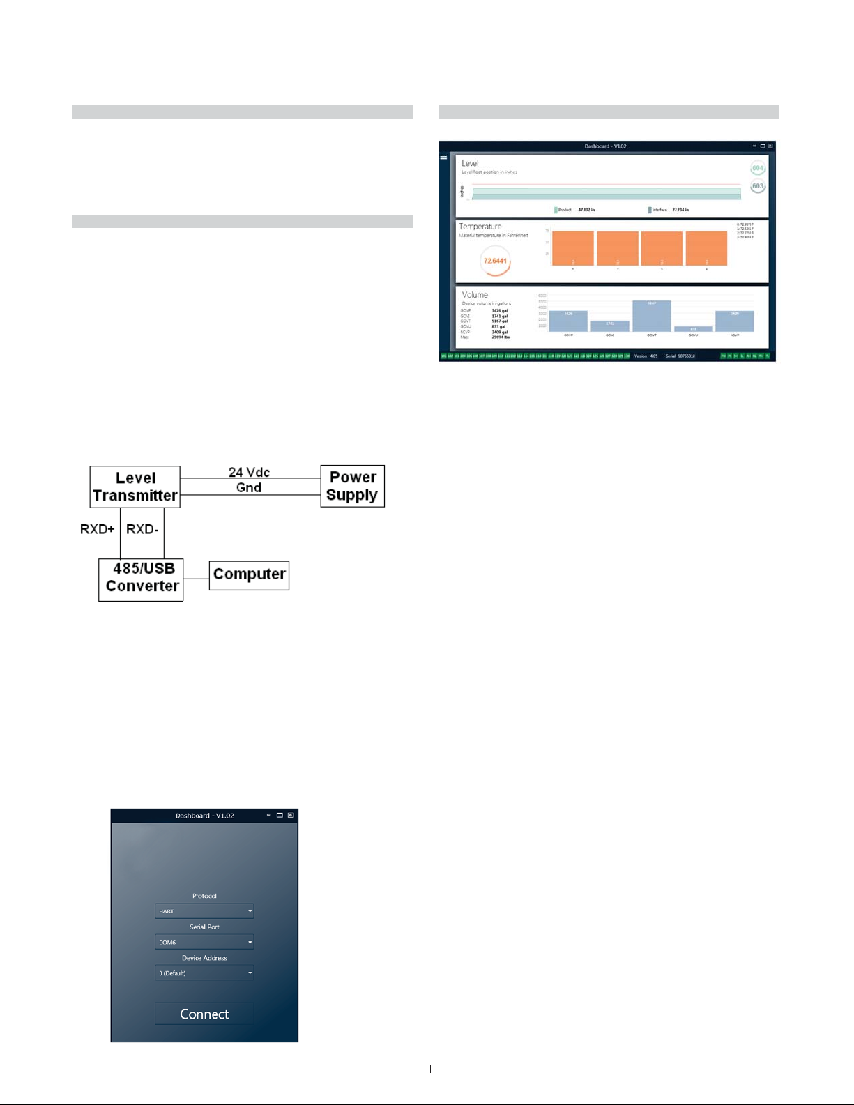
Termination and biasing of RS-485 data lines are as follows:
Each transmitter uses a Fail-Safe, Slew-Rate-Limited RS-
485/RS-422 Transceivers. No additional biasing, resistors should
be present on the connecting devices (PLC, DCS, PC, Converter).
Each transmitter uses a Fail-Safe, Slew-Rate-Limited RS-485/
RS-422 Transceivers. No additional termination resistors are
necessary in connecting devices (PLC, DCS, PC, Converter).
Fault
Code
120 DAC Fault 3 Cycle power to sensor. If proper operation
is not restored, Contact Factory.
121 DAC Fault 4 Cycle power to sensor. If proper operation
is not restored, Contact Factory.
122 SPI Fault 1 Cycle power to sensor. If proper operation
is not restored, Contact Factory.
123 SPI Fault 2 Cycle power to sensor. If proper operation
is not restored, Contact Factory.
124 Setpoint
Fault
The analog setpoints are too close. Mini-
mum distance is 150 mm (6 in.) for analog
and 290 mm (11.5 in.) for SIL. Adjust
programmed setpoints as needed. (Analog
only) If proper operation is not restored,
Contact Factory.
125 Loop 1 Out
of Range
Verify that magnets are positioned within
expected measuring range. Adjust program-
med setpoints as needed. (Analog only) If
proper operation is not restored, Contact
Factory.
126 Loop 2 Out
of Range
Verify that magnets are positioned within
expected measuring range. Adjust program-
med setpoints as needed. (Analog only) If
proper operation is not restored, Contact
Factory.
127 EEPROM
Fault 1
Cycle power to sensor. If proper operation
is not restored, Contact Factory.
128 EEPROM
Fault 2
Cycle power to sensor. If proper operation
is not restored, Contact Factory.
129 Flash Failure Cycle power to sensor. If proper operation
is not restored, Contact Factory.
130 Internal
Error
Cycle power to sensor. If proper operation
is not restored, Contact Factory.

8
Modbus Interface Manual
The Modbus implementation for the digital transmitter conforms to
the ‘Modicon Modbus Protocol Reference Guide, PIMBUS-300 Rev. G’
available from Modicon, Inc. The information provided below assumes
familiarity with the Modbus protocol as outlined in this reference guide.
All information provided applies to Modbus RTU protocol only.
Adjustments to the calibration and setup parameters of the Modbus
interface can be performed using the Dashboard. The dashboard can be
run from any Windows 7 or newer OS using a RS485 to USB converter.
Perform the following steps to install the Dashboard and establish
communication:
1. Install setup software from the USB stick that came with the level
transmitter or go to factory website to download the latest
version.
2. Connect level transmitter to RS485 to USB converter, connect
24 Vdc power to the level transmitter, and connect the RS485 to
USB converter to the PC. Example setup shown below.
Fig. 2: Example setup
3. Open Dashboard and select Modbus protocol from drop down
menu.
4. Select COM Port. Software will show active COM ports. Make sure
converter is connected before starting Dashboard or COM port
will not show.
5. The default address for the level transmitters from the factory is
247. Select address 247. If you do not know the address you can
use the Search function at the bottom of the address range or the
display menu.
Fig. 3: Initial screen
8.1.2 Home screen
Fig. 4: Home screen
The Dashboard Home Screen will look different based on whether or
not temperature has been ordered and volume measurement has been
enabled. If the level transmitter includes temperature measurement
and volume measurement is enabled then the Home Screen will look as
shown. If the level transmitter does not include temperature measurement
then the Home Screen will not show the middle panel for temperature. If
the level transmitter does not have volume measurement enabled then the
Home Screen will not show the bottom panel. The Home Screen can be
accessed by pressing the three white bars on the top left.
The level panel on top shows the level measurement for the Product
level and the graph is a time lapse of the graphical representation of the
numbers. The red line is the approximate maximum level based off of the
order length of the level transmitter. The numbers on the right of the level
panel are the Trigger Level for the Product Float on top and the Interface
Float on bottom. These are a representation of how strong of a return
signal the level transmitter is experiencing.
The temperature panel will only show if temperature measurement
was ordered and turned on. The left side shows the numerical value of
the average temperature of all temperature sensors below the product
level. The bar graph in the middle of the panel shows each individual
temperature measurement point. Temperature 1 is always the lowest
temperature closest to the bottom of the pipe or hose.
The volume panel is on the bottom. On the left side is the numerical
value for GOVP, GOVI, GOVT, GOVU, NSVP, and mass including units.
The bar graph in the middle is a graphical representation of the volume
measurement.
Across the bottom of the Home Screen is the visual indication of the fault
codes from section 8. Green indicates no fault and red indicates fault.
On the far right are the lights for the soft alarms that can be set in the
Dashboard. Green indicates the alarm is not tripped and red indicates that
the alarm has been tripped.

9
Modbus Interface Manual
Fig. 5: Configuration
Factory Set:
Default setting is ON and should not be turned off.
This feature allows the unit to automatically adjust the threshold for
optimal performance.
Default setting of ON for all applications.
Default setting of ON if ordering 2 Loops. Default
the level transmitter will go into Fault.
Serial Number assigned by factory at the time of
manufacture. The serial number is used for tracking and replacement
parts. Do not change.
Default setting of OFF if ordered without temperature.
Default setting of ON if ordered with temperature. Turning tempera-
ture ON when the level transmitter was not ordered with temperature
will not cause temperature to work and will force the level transmitter
into Fault.
Default setting of ON. Display can be turned off by
changing to OFF and cycling power.
Allows the end user to change the direction in
which the level transmitter counts. The default setting is OFF and the
level transmitter will reference the tip of the pipe/hose and count up
from the tip. The ON setting will reference the head of the level trans-
mitter and count up as it moves towards the tip.
Default address is 247. The default address should not be used in a
network.
Allows the end user to select the desired baud rate. Default
setting is 4800.
options are level or volume. Default setting is level.
Allows the end user to turn ON and OFF the volume
calculation.
Fig.6: Signal settings
Factory Set:
Is the speed at which the magnetostrictive signals travel
along the sensing element. Typical range is from 8.9 to 9.2. Do not
change unless replacing the sensing element. Changing this number
will directly affect accuracy.
Is the strength of the interrogation pulse. Factory uses
the same electronics for all lengths and adjusts the signal based on the
order length. Do not change unless instructed to do so by the factory.
Fig. 7: Signal settings

10
Modbus Interface Manual
Factory Set:
a calibration method that directly
changes the offset of the level measurement. The offset is the zero
reference point used in determining the level output. Do not use
without Factory guidance.
the full length of the level transmitter including order
length, inactive zones, and mounting length. Do not change the Enter
Level Offset method without Factory guidance. The offset will change
after using the Enter Current Tank Level for the Product. The Product
Offset and Interface Offset are independent of one another.
the full length of the level transmitter including order
length, inactive zones, and mounting length. Do not change the Enter
Level Offset method without Factory guidance. The offset will change
after using the Enter Current Tank Level for the Interface. The Product
Offset and Interface Offset are independent of one another.
the unit of measurement used for engineering units.
Default is inches if ordered in inches and mm if ordered in mm.
Options include inches, feet, millimeters, centimeters, and meters.
a calibration method that
calibrates the level transmitter based off of one point of measurement.
Select Enter Current Tank Level from the Method drop down box. Go
to Product Level and enter value of current product level based off of
a manual measurement while the tank level is not changing. Go to
Interface Level and enter value of current interface level based off of
a manual measurement while the tank is not changing. Click Update
box in lower left corner when it appears. Level transmitter is now
calibrated.
Soft alarm that can be disabled or enabled by
value in the box then the alarm will become active.
Soft alarm that can be disabled or enabled by
the value in the box then the alarm will become active.
Soft alarm that can be disabled or enabled by
value in the box then the alarm will become active.
Soft alarm that can be disabled or enabled by
the value in the box then the alarm will become active.
Fig. 8: Temperature settings
Factory Set:
transmitter is looking for. The number should match the number of
temperature sensors in the model number.
This is the number of temperature readings
that are averaged together for the temperature output. The higher the
number the more temperature readings that are averaged. The higher
the number the smoother the output but also the slower the update to
changes in the process temperature.
The location of the temperature sensor in reference to the
end of the pipe.
Calibration factor for the temperature sensor. The defaults
setting is 1.0. Do not change unless a new sensing element with
temperature is ordered.
Calibration factor for the temperature sensor. The default
setting is 0.0. Do not change unless a new sensing element with
temperature is ordered.
Change the units of measure for the temperature
settings. Options are Fahrenheit or Celsius.
Soft alarm that can be disabled or enabled
value in the box then the alarm will become active.
Soft alarm that can be disabled or enabled by
value in the box then the alarm will become active.

11
Modbus Interface Manual
Fig. 9: Analog settings
allows the user to select the unit of measure for the
volume output. Available options are liters, cubic millimeters, cubic
meters, cubic inches, cubic feet, gallons, and barrels.
allows the user to select the unit of measure for the
density input. Available options are kilograms, grams, ounces, pounds,
ton, and tonnes.
allows the user to select the unit of measure for the
mass output. Available options are grams per milliliter, grams per liter,
kilograms per cubic meter, kilograms per liter, pounds per cubic inch,
pounds per cubic foot, pounds per gallon, ton per cubic yard, and
tonnes per cubic meter.
allows the end user to select the temperature
correction method from the available API tables including 6A, 6B, 6C,
6C Mod, and Custom Table. Custom Table allows the end user to enter
up to a 50 point custom temperature correction table.
allows the end user to enter the API gravity of the liquid as
Allowable values are 270 to 930. TEC units are 10 E-6/Deg F. Used for
6C Mod correction method.
allows the user to specify the reference temperature
for 6C Mod correction method.
allows the user to input the measured density for mass
calculations
allows the end user to select between using a
strapping table and a sphere. Default setting is Sphere.
allows the end user to enter the working capacity of
the tank so ullage can be calculated.
the radius of the sphere to be used for volume
calculations.
an offset value that should be added to the volume
calculation of the sphere based on tank geometry.
allows the user to select how many strapping tables entry
points to use. Maximum is 200.
allows the user to export the strapping table from the
level transmitter. This should always be done after completing the
strapping table. Save as the site name, tank number, and any other
This can be used when replacing electronics or for tanks of the same
size.
Fig. 10: Flash settings
Allows the end user to reset all settings
back to the original settings as they were when they left the factory.
the Zero and Span set points will reset to factory settings.
If fault code 128 appears red then click the link on
the Dashboard to clear the fault.
Allows the end user to have the level
transmitter automatically turn power off, turn power on, and reboot the
device.

12
Modbus Interface Manual
Fig. 11: Save settings
Allows the end user to upload factory
maintained by factory.
Allows the end user to download a backup
usually performed after Read Settings from Gauge. Note – wait until
all settings have changed from Red to White before writing as the color
change signals that the settings have been updated.
Allows the end user to program the level
transmitter with the factory parameters displayed on the Dashboard.
This task is usually performed after Read Settings from File.
Allows the end user to update all of the
factory parameters displayed on the screen. All settings will turn Red
and then will turn white as they are updated.
factory parameters as the level transmitter was originally setup after
completing testing and calibration at the factory. Factory can provide
of the level transmitter. Contact Technical Support for assistance.
8.2 Programming the display
The display diagram is shown in section 5.2. The display menu
structure is shown in section 5.3. This section explains the details of the
programming available under the different sections of the display. The
factory password for entering the display is 27513.
Allows the user to select if the display shows Length Units or Volume
Units.
Allows the user to change the selected Length Units, Volume Units and/or
Temperature Units.
Address
Allows the user to change the address of the level transmitter. Default
address is 247.
Allows the user to view the strength of the return signal for the product
can be viewed.
Product Level
Allows the user to change the level in engineering units for calibration.
The user should use the Current Level selection and enter the current
without help from Technical Support.
Interface Level
Allows the user to change the level in engineering units for calibration.
The user should use the Current Level selection and enter the current
without help from Technical Support.
Roof Level
Allows the user to change the level in engineering units for calibration.
The user should use the Current Level selection and enter the current
position of the roof. The user is advised not to use the Offset feature
without help from Technical Support.
8.2.3 Factory
Menu section that contains factory parameters. Do not edit these
parameters without talking to Technical Support.
The gradient is a calibration factor that is unique for each transmitter.
Typical values are between 8.9 and 9.2 µs/in.
should not be changed. The serial number is used for tracking and
determining spare parts.

13
Modbus Interface Manual
8.2.3 Factory (Cont.)
Initial blanking distance from the head of the level transmitter. Do not
change.
Measurement of how large an interrogation signal is used. Do not change
without Technical Support.
Threshold level for return signal to qualify as a valid signal and not noise.
Allows the user to turn the temperature measurement on or off.
Turning it on will not cause the temperature to work if no temperature
measurement was ordered.
Change the number of temperature points the level transmitter is looking
for. Changing this number does not change the number of temperature
measurement points that were ordered or whether or not temperature
measurement was ordered.
Baud Rate
Allows the user to select the available baud rate. The default baud rate is
4800.
Allows the user to enable or disable the volume output. The volume
output must be setup using the setup software. The volume output must
be enabled for the display to show volume if selected.
Do not disable.
Reset to Factory
Allows the user to reset the electronics to the original factory settings.
This should be used to return the electronics to a known good state when
troubleshooting.
Communication parameters:
Modbus: 4800 BAUD or 9600 8, N, 1
(Reference) Monitor: Modbus RTU Variable BAUD Rate 8, E, 1
The following Modbus function codes are supported:
Function 03 - Read Holding Registers
Function 04 - Read Input Registers
Function 06 - Preset Single Register
Function 08 - Diagnostics (Subfunction 00, Return Query Data)
Function 08 - Diagnostics (Subfunction 01, Restart Communications
Option)
Function 08 - Diagnostics (Subfunction 04, Force Listen Only
Mode)
Function 16 - Preset Multiple Registers
Function 17 - Report Slave ID
Function 03 -Read Holding Registers
The device responds to this message by returning the contents of the
requested data register(s).
(See ‘Device Modbus Register Maps’ on page 15).
The following implementation-specific considerations apply:
»If an unsupported or reserved register is requested, exception code
#2 is returned (See ‘Device Modbus Register Maps’ on page 15
for unsupported/reserved registers).
»If a register contains an device error a maximum negative value
is returned.
»If a register is blank, indicating that the desired function is not
enabled (e.g., volume calculations) a max negative value is returned.
»Unsupported or reserved bits will always be set to 0. See ‘Device
Modbus Register Maps’ on page 20 for alarm bit definitions.
Function 04 - Read Input Registers
This function is handled exactly the same as Function 03. (Be advised
that all registers are read-only in this implementation).
Function 06 – Preset Single Registers
Confirmation of successful transmission is confirmed when the device
responds by echoing back what was sent.
Function 08 - Diagnostics (Subfunction 00, Return Query Data)
The device responds to this request with the following data:
Slave address: echoed
Function: 08H
Subfunction high: 00H
Subfunction low: 00H
Query data (16-bit): echoed
Error check: 16-bit CRC/8-bit LRC
Function 08 - Diagnostics
(Subfunction 01, Restart Communications Option)

14
Modbus Interface Manual
Note:
The communications event log is not supported. The “Query data” field
is irrelevant (normally, FF00H would clear the log).
If the device is in listen-only mode, the device responds to this
message by switching out of listen-only mode - (resulting in no response
being sent to the request).
If the device is not in listen only mode, it responds as follows:
Slave address: echoed
Function: 08H
Subfunction high: 00H
Subfunction low: 01H
Query data (16-bit): echoed (0000H or FF00H)
Error check: 16-bit CRC/8-bit LRC
Function 08 - Diagnostics
(Subfunction 04, Force Listen-Only Mode)
The device responds to this request by switching to listen-only
mode. Messages are still received and parsed, but no responses
are transmitted. To switch out of listen-only mode, issue a ‘Restart
Communications Option’ request (function 08, subfunction 01) or
cycle power.
Function 16 - Preset Multiple Registers
The device response returns the slave address, function code, starting
address, and quantity of registers preset.
Function 17 - Report Slave ID
The device responds to this request with the following data:
Slave address: echoed
Function: 11H
Byte count: 05H
Slave ID: FFH
Run indicator status: FFH (ON)
Additional data: ‘DMS’
Error check: 16-bit CRC/8-bit LRC
Modbus Exception Codes
The following standard Modbus exceptions are implemented:
Error code 01 (Illegal Function)
Reported when:
»A function other than 03, 04, 06, 08, 16 or 17 is requested
»Function 08 is requested, and a subfunction other than 00, 01,
or 04 is requested, or when invalid register within set is requested.
»Handled by error code 07
Error code 02 (Illegal Data Address)
Reported when:
»Function 03 or 04 is requested and the starting register number
is greater than 5198 (register greater than 35198 or 45198)
»Function 03 or 04 is requested and a register within the requested
register set is invalid
Error code 03 (Illegal Data Value)
Reported when:
»Function 03 or 04 is requested and the number of data points
is greater than 800.
Error code 06 (Busy)
Reported when:
»The device LCD menu is active.
Error code 07 (Illegal Operation)
Reported when:
»Function 06 or 16 is requested while the device is write protected.
»Function 08 is requested with an invalid subfunction.

15
Modbus Interface Manual
30001 0000 Product Level High
Word (x 1000)
2, Page 19
3, Page 19
30002 0001 Product Level Low
Word (x 1000)
30003 0002 Interface Level High
Word (x 1000)
30004 0003 Interface Level Low
Word (x 1000)
30005 0004 Roof Level High Word
(x 1000)
Inactive
30006 0005 Roof Level Low Word
(x 1000)
Inactive
30007 0006 Temperature 1 High
Word (x 10000)
4, Page 19
30008 0007 Temperature 1 Low
Word (x 10000)
30009 0008 Temperature 2 High
Word (x 10000)
30010 0009 Temperature 2 Low
Word (x 10000)
30011 0010 Temperature 3 High
Word (x 10000)
30012 0011 Temperature 3 Low
Word (x 10000)
30013 0012 Temperature 4 High
Word (x 10000)
30014 0013 Temperature 4 Low
Word (x 10000)
30015 0014 Temperature 5 High
Word (x 10000)
30016 0015 Temperature 5 Low
Word (x 10000)
30017 0016 Temperature Average
High Word (x 10000)
5, Page 19
30018 0017 Temperature Average
Low Word (x 10000)
30019 0018 GOVP High Word 6, Page 19
30020 0019 GOVP Low Word
30021 0020 GOVI High Word 7, Page 19
30022 0021 GOVI Low Word
30023 0022 GOVT High Word 8, Page 19
30024 0023 GOVT Low Word
30025 0024 GOVU High Word 9, Page 19
30026 0025 GOVU Low Word
30027 0026 NSVP High Word 10, Page 19
30028 0027 NSVP Low Word
30029 0028 MASS High Word
30030 0029 MASS Low Word
Data
Address
Data
‡denotes duplicate
register
Data
Address
Data
‡denotes duplicate
register
30031 0030 Temperature Cor-
rection Method High
Word
11, Page 19
30032 0031 Temperature Cor-
rection Method Low
Word
30033 0032 API Gravity High
Word (x 100)
30034 0033 API Gravity Low Word
(x 100)
30035 0034 Working Capacity
High Word (x 10)
30036 0035 Working Capacity
Low Word (x 10)
30037 0036 TEC High Word (x
10000000)
12, Page 19
30038 0037 TEC Low Word (x
10000000)
30039 0038 Density High Word
(x 100)
13, Page 19
30040 0039 Density Low Word (x
100)
30041 0040 Reference Tempera-
ture High Word (x 10)
14, Page 19
30042 0041 Reference Tempera-
ture Low Word (x 10)
30043 0042 Volume Calculation
Mode High Word
15, Page 19
30044 0043 Volume Calculation
Mode Low Word
30045 0044 Sphere Radius High
Word (x 10)
16, Page 19
30046 0045 Sphere Radius Low
Word (x 10)
30047 0046 Sphere Offset High
Word (x 10)
17, Page 19
30048 0047 Sphere Offset Low
Word (x 10)
30049 0048 Average Interval High
Word
18, Page 19
30050 0049 Average Interval Low
Word
30051 0050 Alarm/Status High
Word
19, Page 20
30052 0051 Alarm/Status Low
Word
30053 0052 VCF Calculation Error
Status
20, page 20
30054 0053 Volume Calculation
Error Status
21, page 20
30055 0054 Resets the EEPROM
CRC

16
Modbus Interface Manual
Data
Address
Data
‡denotes duplicate
register
Data
Address
Data
‡denotes duplicate
register
30056 0055 Resets the EEPROM
data to factory
30057 0056 Resets the EEPROM
data to defaults
30058 0057 Temperature sensor
status high word
30059 0058 Temperature sensor
status low word
30060 -
30099
0059 -
0098
Reserved 22, page 20
30100 0099 Temperature Units
High
23, page 20
30101 0100 Temperature Units
Low
30102 0101 Density Units High 24, page 20
30103 0102 Density Units Low
30104 0103 Volume Units High 25, page 20
30105 0104 Volume Units Low
30106 0105 Length Units High 26, page 20
30107 0106 Length Units Low
30108 0107 Mass Units High 27, page 20
30109 0108 Mass Units Low
30110 0109 Set New Device
Address
28, page 20
30111 0110 Reboot the device
30112-
30199
0111-0108 Reserved 22, Page 20
30200 199 Product Level High
Word (x1000) ‡
2, Page 19
3, Page 19
30201 200 Product Level Low
Word (x1000) ‡
30202 201 Interface Level High
Word (x1000) ‡
30203 202 Interface Level Low
Word (x1000) ‡
30204 203 Roof Level High Word
(x1000) ‡
Inactive
30205 204 Roof Level Low Word
(x1000) ‡
Inactive
30206 205 Temperature 1 High
Word (x10000)
4, Page 19
30207 206 Temperature 1 Low
Word (x10000)
30208 207 Temperature 2 High
Word (x10000)
30209 208 Temperature 2 Low
Word (x10000)
30210 209 Temperature 3 High
Word (x10000)
30211 210 Temperature 3 Low
Word (x10000)
30212 211 Temperature 4 High
Word (x10000)
30213 212 Temperature 4 Low
Word (x10000)
30214 213 Temperature 5 High
Word (x10000)
30215 214 Temperature 5 Low
Word (x10000)
30216 215 Temperature 6 High
Word (x10000)
30217 216 Temperature 6 Low
Word (x10000)
30218 217 Temperature 7 High
Word (x10000)
30219 218 Temperature 7 Low
Word (x10000)
30220 219 Temperature 8 High
Word (x10000)
30221 220 Temperature 8 Low
Word (x10000)
30222 221 Temperature 9 High
Word (x10000)
30223 222 Temperature 9 Low
Word (x10000)
30224 223 Temperature 10 High
Word (x10000)
30225 224 Temperature 10 Low
Word (x10000)
30226 225 Temperature 11 High
Word (x10000)
30227 226 Temperature 11 Low
Word (x10000)
30228 227 Temperature 12 High
Word (x10000)
30229 228 Temperature 12 Low
Word (x10000)
30230 229 Temperature Average
High Word (x10000)
5, Page 19
30231 230 Temperature Average
Low Word (x10000)
30232 231 GOVP High Word ‡ 6, Page 19
30233 232 GOVP Low Word ‡
30234 233 GOVI High Word ‡ 7, Page 19
30235 234 GOVI Low Word ‡
30236 235 GOVT High Word ‡ 8, Page 19
30237 236 GOVT Low Word ‡
30238 237 GOVU High Word ‡ 9, Page 19
30239 238 GOVU Low Word ‡
30240 239 NSVP High Word ‡ 10, Page 19
30241 240 NSVP Low Word ‡
30242 241 MASS High Word ‡

17
Modbus Interface Manual
Data
Address
Data
‡denotes duplicate
register
Data
Address
Data
‡denotes duplicate
register
30243 242 MASS Low Word ‡
30244 243 Temperature Cor-
rection Method High
Word ‡
11, Page 19
30245 244 Temperature Cor-
rection Method Low
Word ‡
30246 245 API Gravity High
Word (x100) ‡
30247 246 API Gravity Low Word
(x100) ‡
30248 247 Working Capacity
High Word (x10) ‡
30249 248 Working Capacity
Low Word (x10) ‡
30250 249 TEC High Word
(x10000000) ‡
12, Page 19
30251 250 TEC Low Word
(x10000000) ‡
30252 251 Density High Word
(x100) ‡
13, Page 19
30253 252 Density Low Word
(x100) ‡
30254 253 Reference Tempe-
rature High Word
(x10) ‡
14, Page 19
30255 254 Reference Tempe-
rature Low Word
(x10) ‡
30256 255 Volume Calculation
Mode High Word ‡
15, Page 19
30257 256 Volume Calculation
Mode Low Word ‡
30258 257 Sphere Radius High
Word (x10) ‡
16, Page 19
30259 258 Sphere Radius Low
Word (x10) ‡
30260 259 Sphere Offset High
Word (x10) ‡
17, Page 19
30261 260 Sphere Offset Low
Word (x10) ‡
30262 261 Average Interval High
Word ‡
18, Page 19
30263 262 Average Interval Low
Word ‡
30264 263 Alarm/Status High
Word ‡
19, Page 20
30265 264 Alarm/Status Low
Word ‡
30266 265 VCF Calculation Error
Status ‡
20, Page 20
30267 266 Volume Calculation
Error Status ‡
21, page 20
30268 267 Temperature 13 High
Word (x10000)
30269 268 Temperature 13 Low
Word (x10000)
30270 269 Temperature 14 High
Word (x10000)
30271 270 Temperature 14 Low
Word (x10000)
30272 271 Temperature 15 High
Word (x10000)
30273 272 Temperature 15 Low
Word (x10000)
30274 273 Temperature 16 High
Word (x10000)
30275 274 Temperature 16 Low
Word (x10000)
30276 275 Temperature 17 High
Word (x10000)
Inactive
30277 276 Temperature 17 Low
Word (x10000)
Inactive
30278 277 Temperature 18 High
Word (x10000)
Inactive
30279 278 Temperature 18 Low
Word (x10000)
Inactive
30280 279 Temperature 19 High
Word (x10000)
Inactive
30281 280 Temperature 19 Low
Word (x10000)
Inactive
30282 281 Temperature 20 High
Word (x10000)
Inactive
30283 282 Temperature 20 Low
Word (x10000)
Inactive
30284 283 Temperature 21 High
Word (x10000)
Inactive
30285 284 Temperature 21 Low
Word (x10000)
Inactive
30286 285 Temperature 22 High
Word (x10000)
Inactive
30287 286 Temperature 22 Low
Word (x10000)
Inactive
30288 287 Temperature 23 High
Word (x10000)
Inactive
30289 288 Temperature 23 Low
Word (x10000)
Inactive
30290 289 Temperature 24 High
Word (x10000)
Inactive
30291 290 Temperature 24 Low
Word (x10000)
Inactive
30292 291 Temperature 25 High
Word (x10000)
Inactive

18
Modbus Interface Manual
Data
Address
Data
‡denotes duplicate
register
Data
Address
Data
‡denotes duplicate
register
30293 292 Temperature 25 Low
Word (x10000)
Inactive
30294 293 Temperature 26 High
Word (x10000)
Inactive
30295 294 Temperature 26 Low
Word (x10000)
Inactive
30300 299 Temperature Units
High ‡
23, page 20
30301 300 Temperature Units
Low ‡
30302 301 Density Units High ‡ 24, page 20
30303 302 Density Units Low ‡
30304 303 Volume Units High ‡ 25, page 20
30305 304 Volume Units Low ‡
30306 305 Length Units High ‡ 26, page 20
30307 306 Length Units Low ‡
30308 307 Mass Units High ‡ 27, Page 20
30309 308 Mass Units Low ‡
30310 309 Set New Device
Address ‡
28, page 20
30311-
31108
310-1107 Reserved 22, Page 20
31109 1108 Alarm Units High 29, Page 20
31110 1109 Alarm Units Low
31111 1110 Interface High Alarm
High (x 100)
30, Page 21
31112 1111 Interface High Alarm
Low (x 100)
31113 1112 Interface Low Alarm
High (x 100)
31, Page 21
31114 1113 Interface Low Alarm
Low (x 100)
31115 1114 Product High Alarm
High (x 100)
32, Page 21
31116 1115 Product High Alarm
Low (x 100)
31117 1116 Product Low Alarm
High (x 100)
33, Page 21
31118 1117 Product Low Alarm
Low (x 100)
31119 1118 Roof High Alarm High
(x 100)
34, Page 21
31120 1119 Roof High Alarm Low
(x 100)
31121 1120 Roof Low Alarm High
(x 100)
35, Page 21
31122 1121 Roof Low Alarm Low
(x 100)
31123 1122 Temperature Average
High Alarm High
(x100)
36, Page 21
31124 1123 Temperature Average
High Alarm Low
(x 100)
31125 1124 Temperature Average
Low Alarm High (x
100)
37, Page 21
31126 1125 Temperature Average
Low Alarm Low
31127–
37216
1126-7215 Reserved 22, Page 20

19
Modbus Interface Manual
Registers that are read or preset are done so using the current unit
type’s programmed unit.
For example:
If the current unit type is ‘Length’ and you currently have selected ‘Feet’
as your unit, then the value returned will be in that unit. Make sure
the value programmed is also done so using that unit.
1. All registers can be accessed using either Modbus Function
03 (Read Holding Registers) or Modbus Function 04
(Read Input Registers). However, all registers are read-only in
this implementation.
For example:
Registers 30001 and 30002 (using Function 03) can also be
read as registers 40001 and 40002 (using Function 04).
2.
Both values need to be concatenated by the master to form a
32-bit unsigned ‘long word’ quantity.
For example:
Register 30001 (16-bit high word) = 0002H (Must be read
Long word (32-bit) = 00023F8CH (decimal 147340)
Or:
Register 30001 (high word) = 2
Register 30002 (low word) = 16268
Multiply register 30001 x 65536 : 2 x 65536 = 131072
Add result to register 30002 : 131072 + 16268 = 147340
3.
(x 100000000)’ or ‘(x 1000)’ have been scaled (multiplied) by
a factor of 10, 100, 1000, 10000 or 10000000 before
transmission to preserve the fractional portion of the data
value. The master must divide these values by the scale factor
as necessary.
For example:
Register 30001 (16-bit high word) = 0002H
Long word (32-bit) = 00023F8CH (decimal 147340)
Divide by 1000, actual value = 147.340
4.
5.
6.
7. =
8. =
9. =
10. = Standard Volume of Product
11.
1 = (6A) Heavy Oils
2 = (6B) Light Oils
3 = (6C) Chemicals
movable reference temperature (6C Mod).
5 = Custom Table.
12.
Temperature correction method ‘6C’ uses the thermal expansion
the volume correction factor. Allowable values are 270.0 to
930.0. TEC Units are in 10E-6/Deg F.
13.
Temperature correction method ‘6C’ and ‘Custom Table’
requires you to enter the density (at the given reference
temperature) of the product being measured for the net mass
calculation.
14.
This is the desired base temperature for the VCF calculation
when Temperature Correction Method ‘6C Mod’ is used.
15.
This is the mode you wish the volume calculations to be
performed by:
1 = Use Strap Table
0 = Use Sphere Calculation
16.
The radius of the sphere when volume calculations are
performed (using the sphere calculation mode).
17.
The offset of the sphere when volume calculations are
performed (using the sphere calculation mode).
18.
All level, temperature and volume calculation can be
averaged using timed method. Allowable values are as
follows:
0 = 1 second (default)
5 = 5 seconds
10 = 10 seconds
15 = 15 seconds
20 = 20 seconds
25 = 25 seconds
30 = 30 seconds
35 = 35 seconds
40 = 40 seconds
45 = 45 seconds
50 = 50 seconds
55 = 55 seconds
60 = 60 seconds

20
Modbus Interface Manual
19.
D1 Interface Alarm High
D2 Interface Alarm Low
D3 Product Alarm High
D4 Product Alarm Low
D5 Roof Alarm High
D6 Roof Alarm Low
D7 Average Temperature Alarm High
D8 Average Temperature Alarm Low
D9 Magnet Is Missing
D10 Digital Temperature 0 Error
D11 Digital Temperature 1 Error
D12 Digital Temperature 2 Error
D13 Digital Temperature 3 Error
D14 Digital Temperature 4 Error
D15 Digital Temperature Average Error
D16 – D32 Reserved
For each corresponding alarm bit:
0 = ALARM OFF
1 = ALARM ON
Reserved bits will always be set to 0 (OFF).
20.
This value can only be read. If there is no error performing
the volume correction factor then the value is zero otherwise,
the value is a non-zero code and one of the following:
1 = Invalid API value or invalid temperature input value for
6A or 6B VCF calculation.
2 = Invalid API value or invalid temperature input range for
6A VCF calculation.
3 = Invalid API value or invalid temperature input range for
6B VCF calculation.
4 = Invalid API value or invalid temperature input value for
6C VCF calculation.
5 = Invalid API value or invalid temperature range for 6C
VCF calculation.
6 = Invalid API value or invalid temperature range for 6C
Wide VCF calculation.
7 = Invalid delta temperature for 6C VCF calculation.
8 = Interpolation error, temperature value not found in the
table.
9 = Invalid or No VCF method selected.
21.
This value can only be read. If there is no error performing the
volume calculations then the value is zero otherwise the value
Is a non-zero code and one of the following:
1 = Negative table entries are not allowed.
2 = Interpolation error, level value not found in the table.
3 = Sphere Calculation error, level exceeds sphere
radius x 2.
4 = Calculated a negative volume value.
22. will
return a maximum negative value (8000H, or 80000000H for
register pairs). Attempting to read registers outside the
register map (35198 or higher) will cause a Modbus Exception
Error Code 02 (Illegal Data Value) to be returned.
23.
The value for temperature units can be one of the following
codes:
0 = Celsius
1 = Fahrenheit
24.
The value for density units can be one of the following codes:
0 = Grams/Milliliters
1 = Grams/Liter
2 = Kilograms/Cubic Meters
3 = Kilograms/Liter
4 = Pounds/Cubic Inch
5 = Pounds/Cubic Foot
6 = Pounds/Gallon
7 = Tonnes/Cubic Meter
8 = Tons/Cubic Yard
25.
The value for volume units can be one of the following codes:
0 = Liters
1 = Cubic Millimeters
2 = Cubic Meters
3 = Cubic Inches
4 = Cubic Feet
5 = Gallons
6 = Barrels
26.
The value for length units can be one of the following codes:
0 = Millimeters
1 = Centimeters
2 = Meters
3 = Kilometers
4 = Inches
5 = Feet
6 = Yards
27.
The value for mass units can be one of the following codes:
0 = Kilograms
1 = Grams
2 = Ounces
3 = Pounds
4 = Tons
5 = Tonnes
28.
This register will program the new device address. Valid values
for Modbus are between: 1 – 247.
29.
This register programs the unit type for which you can
‘Length’ unit type, however Roof can only be ‘Length’ unit
type.
Valid Values are as follows:
2 = Volume Units Type.
3 = Length Units Type.
Other manuals for KT Series
1
Table of contents
Other Kenco Transmitter manuals
Popular Transmitter manuals by other brands

Omnitronic
Omnitronic WAMS-65BT user manual

Fukuda Denshi
Fukuda Denshi LX-7230N Operation manual

PTN
PTN TPVG201 user manual

Julius Mayer
Julius Mayer JMWS-1 Original instructions

Meld Technology
Meld Technology MT300 Operator's manual

Moog Videolarm
Moog Videolarm PM24M58 Installation and operation instructions