Happijack Camper Jack User manual

1.
2.
3.
4.
Camper Jack
Owners Manual
Operating Instructions
CAREFULLY READ THESE INSTRUCTIONS BEFORE USING THE
HAPPIJAC CAMPER JACKS. CAUTION: NEVER RAISE JACKS
ABOVE RED SAFETY LINE MARKED ON INNER JACK LEG.
Load & unload camper on basically level ground, never on an obvious grade.
Use 12” sq. 3/4” plywood support pads under each jack to prevent sinking into
the ground or asphalt
Use extreme caution when the wind is blowing. Avoid storing camper in
windy, unsheltered areas and prevent snow accumulation on camper roof.
Secure camper with tie downs when stored outdoors.
Camper should be supported on a sturdy base during storage to prevent
damage to camper floor and the wing walls. When living in camper, the floor
should be firmly supported.
When leveling with the camper on the truck –
Unloading Your Camper
Make sure electrical connections and all tie downs are disconnected
between camper and truck body.
Insert crank handle (if using manual jacks) firmly into the crank socket
of one of the front jacks and begin cranking counter-clockwise to
extend. Raise the front of the camper 3” to 4” working side to side (if
alone) or together if 2 people are unloading.
Repeat step2 for the rear corners, then go back to the front and repeat
step 2. Caution: Never raise the back of the camper higher than
the front.
When the camper floor is clear of the truck bed (3” to 6”) slowly drive
the truck forward, being very careful not to hit the jacks or the camper.
Caution: Fill holes or move rocks that could cause the truck to
pitch into the jacks or the camper.
LOWER CAMPER: Insert crank handle into crank socket of either
rear jack and begin cranking clockwise (if using manual jacks). Lower
the rear 3” to 4” working side to side or together if more than one is
cranking. Move to the front and do the same. Work back and forth in
3” to 4” increments until desired height is reached.
For added safety and stability, support the camper floor with blocks
and use camper jacks to stabilize.
1.
2.
3.
4.
5.
6.
1.
2.
3.
4.
5.
Loading Your Camper
Raise camper, (see steps 2& 3 of the UNLOADING YOUR
CAMPER section) until the bottom of the camper is higher than
truck bed by 3” to 6”.
Slowly back the truck under the camper. Make sure truck and
camper are aligned so as not to hit the jacks or the camper with
truck fenders or wheel wells. See also the Caution in step 4
above. Connect electrical cables while accessible.
Lower camper onto truck bed. Crank clockwise on rear jacks first
lowering 3” to 4” then move to the front and do the same. Repeat
until the truck takes the full weight of the camper, then secure
camper to truck.
Completely retract all 4 jacks and stow crank handle.
1.
2.
3.
4.
Maintenance
Frequently - check all mounting screws and other hardware for
tightness & proper jack alignment.
Every 6 months - wax mounting brackets and both inner and outer
tubes of jack with automotive wax.
Once each year - fully extend jacks to red safety line. This
redistributes lubrication evenly on the screw shaft. Remove top
cap and regrease gears (if needed) with white lithium grease.
Lightly oil bearings.
Support Services
For information regarding upgrading these jacks to remote
controlled electric powered units, or for parts, technical support,
or information regarding our other fine products, please contact
us via one of the following:
General Instructions
ALWAYS disconnect the camper tiedowns before leveling. Jacks are
not designed to lift both camper & truck! Damage can occur to jacks,
tiedowns and truck! Overloading jacks can result in jack failures.
Release Locking Lever (Down Position) at top of jack when cranking.
Be sure to reset Locking Lever (Up Position) when jacks are not
being cranked to avoid accidental jack extension.
Free
Locked
After periods of non-use, or anytime
jack seems to labor more than usual,
place a few drops of light oil, ie: 3 in 1R
into the oil hole in the crank socket then
run the jack to distribute the oil. Oil Here
Crank
Socket
HAPPIJAC
Installation Instructions
READ CAREFULLY BEFORE STARTING
Tools and Materials Required
• Electric drill & 5/32” drill bit
• 1/4” nut driver or socket
• 3/8” wrench or socket wrench
• Weather proof putty tape (available at RV stores)
• Extra hardware as required (See section 5
- Clear Silicone Sealant
• Hacksaw
• Wrench
• Mallet
The Front Jacks
Mount to either a “Z” or “T” bracket configuration. The Z + (L)
bracket is the most common and is shown in the following
illustrations.
Secure the L brackets to the Z brackets using # 8 sheet metal screw
at small hole marked X in figure 1 (Start from L side).
Determine the proper location for each bracket (see fig. 1) and
ensure that there is a strong solid load bearing corner in the
camper.
Mark, and remove any corner molding that will interfere with flush
fit of bracket against camper.
Cover inside surface of Z & L bracket 9side against camper) with
the weatherproof putty
tape and seat in place
Drill 5/32” pilot hole
at location 1, (fig. 1)
and secure bracket with
a #14 hex head sheet
metal screw. With all
slotted holes, place
screw at end of slot
furthest from corner of
camper, to allow bracket
to draw down tight.
Note: These screws are not
provided because of the vary-
ing wall thickness from camper
to camper. CAUTION: Be very
careful to select a screw which
will give maximum penetration
without piercing inner wall of
camper(normally 1-1/2”).
1.
2.
3.
4.
5. 5
9
3
11
7
against camper corner
by tapping with mallet. 6
10
4
2
12
8
A
B
C
D
E
F
G
16” Reinforcing
Bracket Camper
Side Wall
Drill pilot
hole in
end
furthest
from
corner
16” Z
Mounting
Bracket
Mount Bracket Flush with
Bottom of Wing Wall
1

Install screws at
locations 2 thru 8
and tighten in that
order. Re-tighten in
the same order.
(Careful, don’t over
tighten and strip
wood or twist off
screw head.)
Install screws 9 &
11 and tighten.
Holes 10 & 12 may
be secured with a
bolt as shown in fig.
2 (best when
possible). If not,
6.
7.
8.
9.
10.
11.
Optional Carriage Bolts
Sheet metal screws can be used in
these bracket holes provided they
do not penetrate the inner wall
WOOD
CORE
WOOD
CORE
Camper
Side Wall
Weatherproof
putty tape
16” Z Bracket
#14 Hex
Head Sheet
Metal Screws
TOPOF
JACK
3/8” Self-locking
Nut & Flat Washer
Torque = 25 Ft. Lbs.
(Do Not Exceed)
16” L Bracket
Fig. 2 - Drivers Side Front Corner (looking downward)
Sheet metal screws can be used if material exists in camper to hold screw
securely.
Secure the L bracket to camper with #14 sheet metal screws described in
step 5. Start at center and work out to ends. As with the Z bracket, bolts
can be used, if possible, in the 2 larger holes (see fig. 2).
Trim away excess putty tape and seal around edge of brackets with clear
silicone sealant.
Mount the jack to the bracket by placing the 3/8” stud bolts on jack through
holes A, D & G (fig. 1). Secure with 3/8” flat washer and self-locking nut
(fig. 2). Torque = 25 Ft. Lbs. (Do Not Exceed) Note: Alternate installation
scheme may require a bolt rather than a stud and nut at hole G.
The Rear Jacks
The Rear Jacks mount to “Z” bracket in combination with either a 5”
lower Z bracket or the 16” L reinforcing bracket. The 5” Z bracket
configuration is most common and is shown in the following illustration.
Determine the proper location for each bracket (see fig. 3). Brackets
must be placed vertically at a point where the foot of the jack just extends
below the bottom of the camper when fully retracted. NOTE: Alignment
of the 16” & 5” brackets is critical. A good way to ensure proper
alignment is to bolt both to the jack and then set in place and mark
location.
Mark, and remove any corner molding that will interfere with flush fit of
bracket against camper.
Cover inside surface of brackets (side against camper) with the
weatherproof putty tape and seat in place against camper corner by
tapping with mallet.
NOTE: If jack will not align with brackets, loosen
bracket screws and draw brackets into alignment, then
with jack in place, tighten accessible bracket screws.
Remove jack and tighten remainder of screws.
5
9
1
3
11
7
6
10
4
2
12
8
A
B
C
D
E
F
G
Fig. 3 - Passenger Side Rear
5” Z
Mounting
Bracket
16” Z
Mounting
Bracket
Numbers
show
tightening
sequence
H
I
J
3
1
5
6
2
4
Mount 16” Z bracket
in same manner as
front installation. If
using the 16” L
reinforcement bracket,
screw it to the Z
bracket before
installing on camper.
16” Z bracket in same
manner as front
installation. If using
the 16” L
reinforcement bracket,
screw it to the Z
bracket before
installing on camper.
Check bracket
alignment by installing
jack.
If alignment is good
and jack installs
properly, clean away
all excess putty tape
and seal around edges
of brackets with clear
silicone.
1.
2.
3.
4.
5.
6.
7.
lectric Jack Option
All mechanical Happijac camper jacks (Acme Screw, Ball-
Screw, and Ball-Screw with Quick-release Leg) are fully
upgradeable to electric jacks. There is no need to buy new
jacks, all you need to do is buy the Motor Drive Assembly Kit
(and the Wiring Kit if your camper did not come prewired for
Happijac electric jacks), which you can install yourself, and
you are ready to enjoy the ease and comfort of remote
controlled electric jacks.
Other manuals for Camper Jack
1
Other Happijack Other manuals
Popular Other manuals by other brands

Toyota
Toyota VERSO - S installation instructions
Conceptronic
Conceptronic CLLRCMCE user guide
HURST
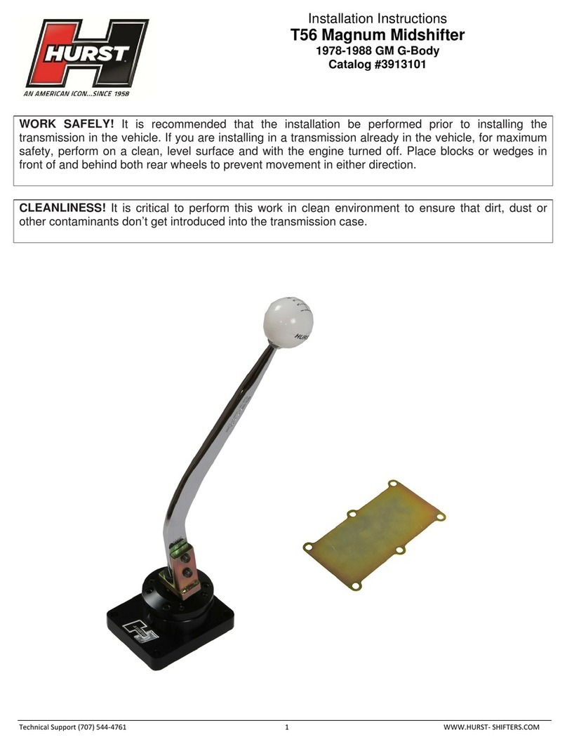
HURST T56 installation instructions
Clearlite Bathrooms
Clearlite Bathrooms Angle Corner installation instructions
Bestop
Bestop Tigertop installation instructions

Aquatop
Aquatop NANOPONIC Series owner's manual
Euphonix
Euphonix System 5 manual

Aquadistri
Aquadistri Superfish FISH FEEDER manual
POLTI
POLTI Forzaspira AG100 Instructions for use
EHEIM
EHEIM Professionel 3 2180 operating instructions

Storch
Storch Hot Box 240 Translation of the original instruction
Roger
Roger BIONIK Series Instruction and warnings for the installer

