schmersal AZS 2305.1 User manual

AZS 2305
Operating instructions
Fail-safe delay timer
EN 1
1. About this document
1.1 Function
This operating instructions manual provides all the information you
need for the mounting, set-up and commissioning to ensure the safe
operation and disassembly of the safety switchgear. the operating
instructions must be available in a legible condition and a complete
version in the vicinity of the device.
1.2 Target group: authorised qualified personnel
All operations described in this operating instructions manual must
be carried out by trained specialist personnel, authorised by the plant
operator only.
Please make sure that you have read and understood these operating
instructions and that you know all applicable legislations regarding
occupational safety and accident prevention prior to installation and
putting the component into operation.
The machine builder must carefully select the harmonised standards
to be complied with as well as other technical specifications for the
selection, mounting and integration of the components.
1.3 Explanation of the symbols used
Information, hint, note:
This symbol is used for identifying useful additional information.
Caution: Failure to comply with this warning notice could
lead to failures or malfunctions.
Warning: Failure to comply with this warning notice could
lead to physical injury and/or damage to the machine.
1.4 Appropriate use
The products described in these operating instructions are developed to
execute safety-related functions as part of an entire plant or machine. It
is the responsibility of the manufacturer of a machine or plant to ensure
the correct functionality of the entire machine or plant.
The safety switchgear must be exclusively used in accordance with
the versions listed below or for the applications authorised by the
manufacturer. Detailed information regarding the range of applications
can be found in the chapter "Product description".
1.5 General safety instructions
The user must observe the safety instructions in this operating
instructions manual, the country specific installation standards as well
as all prevailing safety regulations and accident prevention rules.
Further technical information can be found in the Schmersal
catalogues or in the online catalogue on the Internet:
www.schmersal.net.
The information contained in this operating instructions manual is
provided without liability and is subject to technical modifications.
There are no residual risks, provided that the safety instructions as well
as the instructions regarding mounting, commissioning, operation and
maintenance are observed.
Content
1 About this document
1.1 Function ..............................................1
1.2 Target group: authorised qualied personnel..................1
1.3 Explanation of the symbols used ...........................1
1.4 Appropriate use ........................................1
1.5 General safety instructions ...............................1
1.6 Warning about misuse ...................................2
1.7 Exclusion of liability .....................................2
2 Product description
2.1 Ordering code .........................................2
2.2 Special versions........................................2
2.3 Purpose ..............................................2
2.4 Technical data .........................................2
2.5 Safety classication .....................................2
3 Mounting
3.1 General mounting instructions .............................3
3.2 Dimensions ...........................................3
4 Rear side Electrical connection
4.1 General information for electrical connection..................3
5 Operating principle and settings
5.1 Operating principle after the operating voltage is switched on ....3
5.2 Setting of the time "T" ...................................3
6 Set-up and maintenance
6.1 Functional testing.......................................4
6.2 Maintenance ..........................................4
7 Disassembly and disposal
7.1 Disassembly...........................................4
7.2 Disposal ..............................................4
8 Appendix
8.1 Wiring example ........................................4
8.2 Integral System Diagnostics (ISD)..........................5
9 EU Declaration of conformity
x.000 / 11.2017 / v.A. - 101126753-EN / F / 2017-11-13 / AE-Nr. 8370
EN Operating instructions. . . . . . . . . . . . .pages 1 to 6
Original

2
Operating instructions
Fail-safe delay timer AZS 2305
EN
1.6 Warning about misuse
In case of improper use or manipulation of the safety switch-
gear, personal hazards or damages to machinery or plant
components cannot be excluded. The relevant requirements
of the standard ISO 14119 must be observed.
1.7 Exclusion of liability
We shall accept no liability for damages and malfunctions resulting from
defective mounting or failure to comply with this operating instructions
manual. The manufacturer shall accept no liability for damages
resulting from the use of unauthorised spare parts or accessories.
For safety reasons, invasive work on the device as well as arbitrary
repairs, conversions and modifications to the device are strictly
forbidden; the manufacturer shall accept no liability for damages
resulting from such invasive work, arbitrary repairs, conversions and/or
modifications to the device.
2. Product description
2.1 Ordering code
This operating instructions manual applies to the following types:
AZS 2305.
➀
No. Option Description
➀
24 VDC
1 110 VAC
2 230 VAC
Only if the information described in this operating instructions
manual are realised correctly, the safety function and therefore
the compliance with the Machinery Directive is maintained.
2.2 Special versions
For special versions, which are not listed in the order code below 2.1,
these specifications apply accordingly, provided that they correspond to
the standard version.
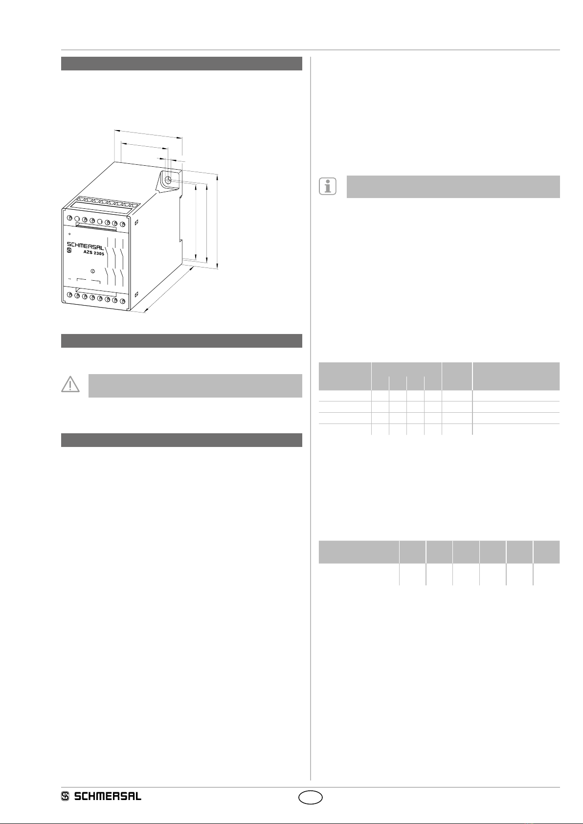
2.3 Purpose
The fail-safe delay timer is designed for control cabinet mounting. It is
used wherever a safe rating of a time "T" is required due to the inertial
movement of a machine or due to the operating time of the plant.
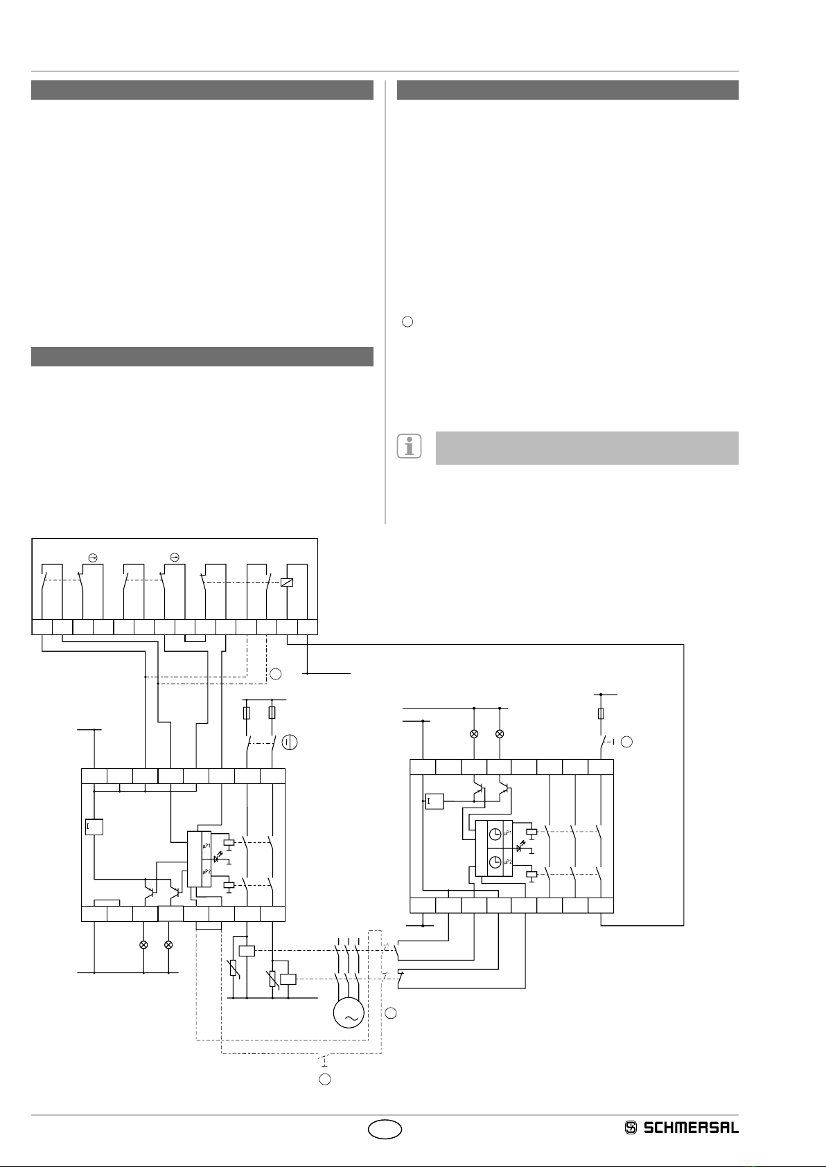
Design/operating principle
The fail-safe delay timer has a dual-channel structure. The time is
manually set in each channel by means of rotary and sliding switches
(refer to Setting the time "T"). It includes two safety relays with
monitored positive action contacts. The series-wired relay contacts
build the enabling paths.
The entire concept of the control system, in which the safety
component is integrated, must be validated to the relevant
standards.
2.4 Technical data
Standards: IEC 60204-1; ISO 13849-1; IEC 61508
Enclosure: glass-fibre reinforced thermoplastic
Mounting: snaps onto standard DIN rail to EN 60715
Connection: Screw connection: max. 2.5 mm²
(including conductor ferrules)
Protection class: terminals IP20,
enclosure IP40
to IEC 60529
Start conditions: Automatic
Rated operating voltage Ue:AZS 2305: 24 VDC ± 15%;
AZS 2305.1: 110 VAC ± 15%;
AZS 2305.2: 230 VAC ± 15%
Rated operating current: 0.1 A at 24 VDC
Power consumption: < 5 W
Rated insulation voltage: 250 V
Rated impulse withstand voltage: 4 kV
Thermal test current Ithe:6 A
Internal electronic fuse: yes
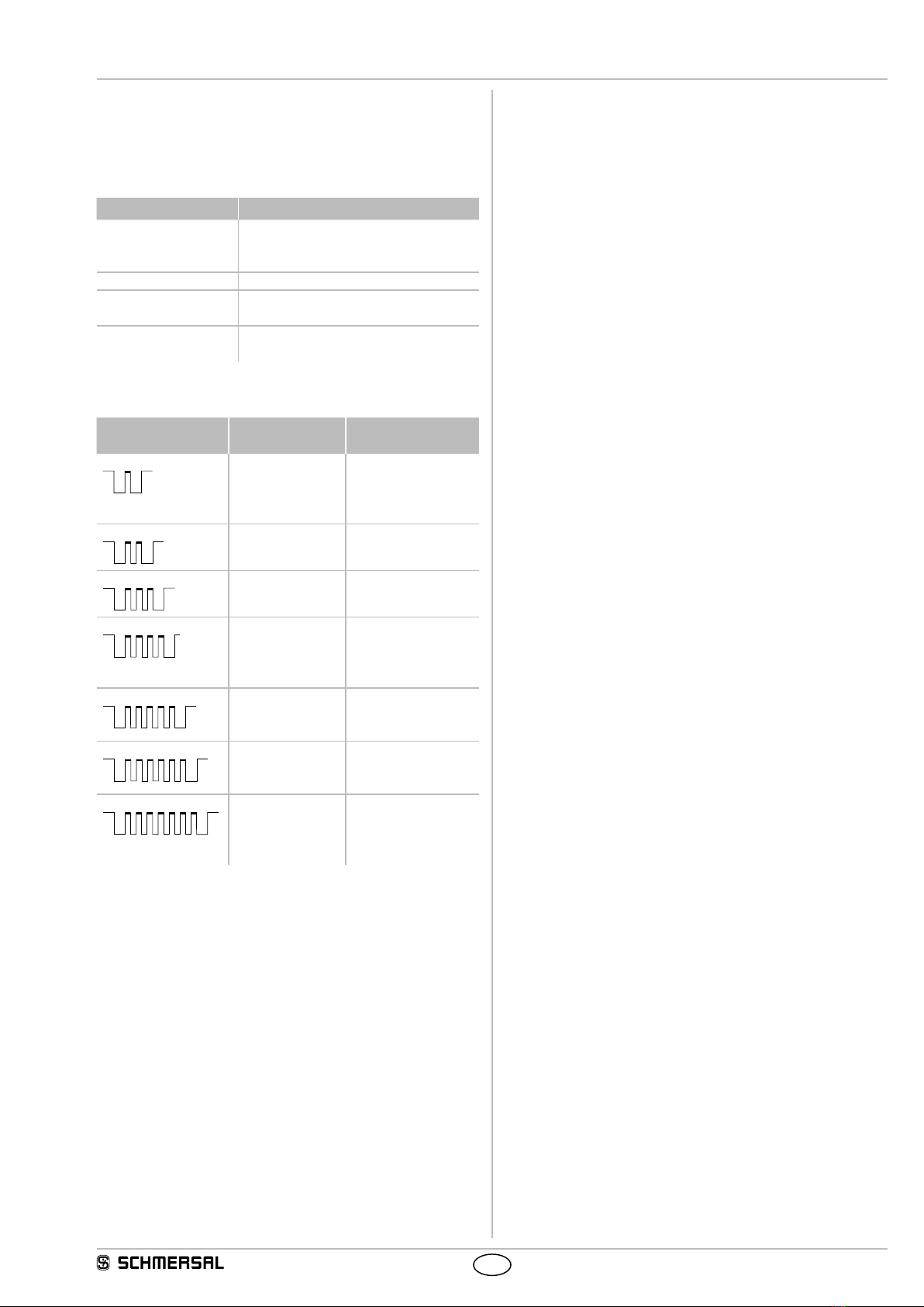
Time range: 0.1 s … 99 min
tmin:0.1 s
tmax:99 min
Time tolerance: < 2 %
Inputs monitoring: S1 (S14), S1 (S22)
Cross-wire detection: yes
Wire breakage detection: yes
Earth connection detection: yes
Input resistance: approx. 2 kΩ against GND
Input signal "1": 10 … 30 VDC
Input signal "0": 0 … 2 VDC
Outputs:
- 13-14 / 23-24 / 33-34: 3 enabling paths each with
2 NO relay contacts in series
Utilisation category: AC-15, DC-13
Rated operating voltage/current Ue/Ie:2 A/250 VAC;2 A/24 VDC
Switching voltage: max. 250 VAC
Load current: max. 3 A (ohmic load)
Switching capacity: max. 750 VA
Max. fuse rating: 6 A (quick blow) incoming
series connected
Additional outputs: Y1, Y2, Ue- 4 V; 100 mA,
short-circuit proof, p-type
Ambient temperature: 0 °C … +55 °C
Storage and transport temperature: −25 °C … +70 °C
Max. cable length: 100 m of 0.75 mm² conductor
Max. switching frequency: 10 Hz
Resistance to vibration: 10 … 55 Hz;
amplitude 0.35 mm ±15%
at the control circuit
Resistance to shock: 30 g / 11 ms
EMC rating: conforming to EMC Directive
2.5 Safety classification
Standards: ISO 13849-1; IEC 61508
PL: up to d
Control category: up to 3
PFH value: 1.0 x 10⁻⁷ / h
SIL: up to 2
Service life: 20 years

3
AZS 2305
Operating instructions
Fail-safe delay timer
EN
3. Mounting
3.1 General mounting instructions
Mounting: snaps onto standard DIN rails to EN 60715.
3.2 Dimensions
All measurements in mm.
110
60
62.5
75
55
37.5
4.5
A2 S13
S1
S14 S21 S22 14 24 34
Made in Germany Wuppertal
Funktion
A1 Y2
Y1 33
23
13
4. Rear side Electrical connection
4.1 General information for electrical connection
The electrical connection may only be carried out by
authorised personnel in a de-energised condition.
Wiring examples: see appendix.
5. Operating principle and settings
5.1 Operating principle after the operating voltage is switched on
1. The functioning of the fail-safe delay timer is checked.
2. An initialisation stage is started during the parity check of the set
time values. In case of varying time values, the red LED is on. The
initialisation stage of the fail-safe delay timer is maintained until both
times are matching due to modification of the switches positions.
3. The fail-safe delay timer is in starting position, when the NO contact
at S1 (S13/S14) is closed and the NC contact at S1 (S21/S22) is
opened. The relay contacts are open and the time registration is
stopped. In case of a signal change at both inputs, the rating of the set
time is started. The yellow LED is intermittently on. The LED flashes
during these intermissions. The minimum unoccupied cycle time can be
determined by means of the number of these impulses (see Table 2). In
case of an unoccupied cycle time of one minute, the impulse frequency
will increase permanently until the relay contacts are closed after
expiration of this time.
4. The input signal at S1 is continuously monitored. In case of a
change, the relay contacts are opened and the time measurement is
stopped.
Signal input S1
S13/S14: connection NO contact
S21/S22: connection NC contact
Outputs
Enabling paths 13-14/23-24/33-34
NO contacts for safety functions
Additional outputs Y1/Y2
Y1: "Enabling signal"; the enabling paths are closed
Y2: "Error"; if the fail-safe delay timer detects an error, Y2 is switched.
The additional outputs Y1 and Y2 must not be integrated in
the safety circuit.
5.2 Setting of the time "T"
The setting of time "T" is realised by means of rotary and sliding
switches and is only saved after the operating voltage is switched
on. The sliding switches are changing the time factor and the rotary
switches the numerical value. To change the time, the enclosure cover
must be removed. (Caution: please observe the handling prescriptions,
electroshock hazard). The symbols of the rotary and sliding switches
are represented at the rear of the cover. These switches must have
the same setting for channel I and II. By rotating the upper rotary
switch, the unit position and by rotating the lower rotary switch the tens
position of the numerical value is changed. The time "T" is calculated by
multiplying the numerical value and the time factor.
Table 1: Representation of the sliding switch positions and their
assigned time factor
Time range Sliding switch Time
factor
Time "T"
1234
0.1 … 9.9 s 1 0 1 0 0.1 s Numerical value x 0.1 s
1.0 … 99 s 0 0 0 0 1.0 s Numerical value x 1.0 s
10 … 990 s 0 1 0 1 10 s Numerical value x 10 s
1.0 … 99 min 1 1 1 1 60 s Numerical value x 60 s
Determination of the unoccupied cycle time
During the rating of the time "T", the yellow LED flashes with brief
impulses. The residual unoccupied cycle time can be derived from
the number of these impulses. Table 2 represents the remaining
unoccupied cycle time depending on the impulses.
Table 2: Number of impulses depending on the unoccupied cycle
time
Number of
impulses n 123456
Minimum unoccupied
cycle time T/2 T/4 T/8 T/16 T/32 T/64

4
Operating instructions
Fail-safe delay timer AZS 2305
EN
6. Set-up and maintenance
6.1 Functional testing
The safety function of the safety-monitoring module must be tested.
The following conditions must be previously checked and met:
1. Correct fitting of the safety-monitoring module
2. Fitting and integrity of the power cable
6.2 Maintenance
In the case of correct installation and adequate use, the safety-
monitoring module features maintenance-free functionality.
A regular visual inspection and functional test, including the following
steps, is recommended:
• Check the correct fixing of the safety monitoring module
• Check the cable for damage.
Damaged or defective components must be replaced.
7. Disassembly and disposal
7.1 Disassembly
The safety monitoring module must be disassembled in the de-
energised condition only.
7.2 Disposal
The safety monitoring module must be disposed of in an appropriate
manner in accordance with the national prescriptions and legislations.
AZS 2305
L1
A1
100mA
S13
K1
14 24 34A2
max.
Y1 Y2
3
K2
S14 S21 S22
13 23 33
+24 VDC
0V
0V
M
E
S
H2
L1
K3
K4
+24 VDC
N
N
0
H1
AES 1235
14
A1
100mA
S13
K1
A2
max.
Y1 X1
K2
S14 S21 S22 13 23
24
A1
A2 Y2 X2
0V
A1 A2
1413 21 22 33 34 41 42 51 52 63 64
AZM 161
8. Appendix
8.1 Wiring example
The application examples shown are suggestions. They however do not
release the user from carefully checking whether the switchgear and its
set-up are suitable for the individual application.
Monitoring of a sliding, hinged or removable safety guard with a
solenoid interlock of the AZM 161 series. The safety guard monitor of
the series AES monitors the position of the safety guard.
The wiring diagram is shown with guard doors closed and in a de-
energised condition. Inductive loads (e.g. contactors, relays, etc.) are to
be provided with suitable interference suppression circuitry.
Key
E
Unlock solenoid interlock
R
Optional: Safety guard must not be opened after the release
S
Optional: Feedback circuit increases the safety,
but not the control category
H
Start button (optional)
To be observed for AC variants: AC supply through A1-A2,
GND of the internal 24 VDC control voltage is on terminal PE.

5
AZS 2305
Operating instructions
Fail-safe delay timer
EN
8.2 Integral System Diagnostics (ISD)
The safety monitoring modules LED display to show the different
switching conditions and faults. The following tables show the different
switching conditions.
Tables switching condition indication
Diagnostic LED System condition
The LED is red. Comparison time value channel I with time
value channel II faulty (setting coding and
sliding switches)
The LED is green. Enabling paths closed
LED flashes yellow
(0.5 Hz)
Input signal in starting position,
enabling paths opened
The yellow LED is flas-
hing (refer to table 2).
Time rating realised, maximum residual
time value can be derived from table 2
Table error indications
Indication (orange)
LED
Error Cause
1 impulse Input signal S14/
S22 at S1
Feeder cable for signal
input S1 defective;
Error during signal
change*
2 impulses Time processing Time value channel I
too high
3 impulses Time processing Time value channel II
too high
4 impulses Interference at
inputs, no safe
evaluation
Too high capacitive or
inductive interference
at the inputs or the
supply voltage lead
5 impulses One or both relays
did not close within
the monitoring time
Too low operating
voltage Ue;
Defective relay
6 impulses Relays not deacti-
vated upon signal
change
Welded relay contact
7 impulses Dynamic monitoring
of both channels
(cross-monitoring)
failure
Internal data transmis-
sion interrupted
* Signal change:
The signal change has only occurred at one input or the signal change
has occurred at both inputs with intervals of over 5 seconds.
Deleting the error message
The fault message is deleted once the fault has been rectified and after
the input signal S1 has been switched to starting position to check the
various functions.

6EN
AZS2305-D-EN
Operating instructions
Fail-safe delay timer AZS 2305
9. EU Declaration of conformity
Name of the component: AZS 2305
Type: Refer to ordering code
Description of the component: Fail-safe delay timer
Relevant Directives: Machinery Directive
EMC-Directive
RoHS-Directive
2006/42/EC
2014/30/EU
2011/65/EU
Applied standards: EN ISO 13849-1:2008 + AC:2009,
EN 61508 parts 1-7:2010.
EN 62061:2005 + AC:2010 + A1:2013
Notied body for the prototype test: TÜV Rheinland Industrie Service GmbH
Alboinstr. 56, 12103 Berlin
ID n°: 0035
EC-prototype test certicate: 01/205/0715.01/15
Person authorised for the compilation
of the technical documentation:
Oliver Wacker
Möddinghofe 30
42279 Wuppertal
The currently valid declaration of conformity can be
downloaded from the internet at www.schmersal.net.
K. A. Schmersal GmbH & Co. KG
Möddinghofe 30, D - 42279 Wuppertal
Postfach 24 02 63, D - 42232 Wuppertal
Phone: +49 - (0)2 02 - 64 74 - 0
Telefax: +49 - (0)2 02 - 64 74 - 1 00
E-Mail: [email protected]
Internet: http://www.schmersal.com
Place and date of issue: Wuppertal, June 8, 2017
Authorised signature
Philip Schmersal
Managing Director
EU Declaration of conformity
Original K.A. Schmersal GmbH & Co. KG
Möddinghofe 30
42279 Wuppertal
Germany
Internet: www.schmersal.com
We hereby certify that the hereafter described components both in their basic design and construction conform
to the applicable European Directives.
This manual suits for next models
1
Table of contents
Popular Other manuals by other brands

Nedap
Nedap Transit Ultimate installation guide

CHART
CHART Orca MicroBulk CO2 Series product manual

Festo
Festo LOGO! EduTrainer TP operating instructions

BELLA LEEZA
BELLA LEEZA LED Mirror Operation manual

progressive automations
progressive automations flt-06 user manual

Happy Frizz
Happy Frizz ZERO Use and maintenance manual