manuals.online logo
Brands
  1. Home
  2. •
  3. Brands
  4. •
  5. Harbor Breeze
  6. •
  7. Adapter
  8. •
  9. Harbor Breeze 40030 User manual

Harbor Breeze 40030 User manual

This manual suits for next models

5

Popular Adapter manuals by other brands

Mini Gadgets BB2Outlet user manual

Mini Gadgets

Mini Gadgets BB2Outlet user manual

LSI LSISAS3442E-R Quick installation guide

LSI

LSI LSISAS3442E-R Quick installation guide

Moeller BBA -16 Series installation instructions

Moeller

Moeller BBA -16 Series installation instructions

Acer MWA3 quick start guide

Acer

Acer MWA3 quick start guide

Connect Tech ADG095 user guide

Connect Tech

Connect Tech ADG095 user guide

cable matters 604002 user manual

cable matters

cable matters 604002 user manual

Solwise PL-85PEW Easy start

Solwise

Solwise PL-85PEW Easy start

HP Photosmart 7100 user guide

HP

HP Photosmart 7100 user guide

HP E2494A installation guide

HP

HP E2494A installation guide

StarTech.com USB150WN1X1 quick start guide

StarTech.com

StarTech.com USB150WN1X1 quick start guide

Lindy 43198 user manual

Lindy

Lindy 43198 user manual

A&D AD-8527 instruction manual

A&D

A&D AD-8527 instruction manual

Motorola WU830G user guide

Motorola

Motorola WU830G user guide

Hawking HUF2 Specifications

Hawking

Hawking HUF2 Specifications

Allen-Bradley E3 Plus installation instructions

Allen-Bradley

Allen-Bradley E3 Plus installation instructions

Trust BT-2210Tp manual

Trust

Trust BT-2210Tp manual

HP NC7170 overview

HP

HP NC7170 overview

Uconnect BLE-485C user manual

Uconnect

Uconnect BLE-485C user manual

manuals.online logo
manuals.online logoBrands
  • About & Mission
  • Contact us
  • Privacy Policy
  • Terms and Conditions

Copyright 2025 Manuals.Online. All Rights Reserved.

ANGLED CEILING ADAPTER
ITEM #0805608, 0829276, 0829277
MODEL #40030, 40295, 40294
Harbor Breeze®is a registered trademark of LF,
LLC. All rights reserved.
EB1695 1
Purchase Date
ATTACH YOUR RECEIPT HERE
PACKAGE CONTENTS
HARDWARE CONTENTS (shown actual size)
PART DESCRIPTION QUANTITY
A Ball 1
B Mounting Bracket 1
C Canopy 1
D Canopy Cover (preassembled to Canopy [C]) 1
EBall Adapter 1
A
AA BB CC DD EE
D
E
B
C
PREPARATION
SAFETY INFORMATION
WARNING
CAUTION
Please read and understand this entire manual before attempting to assemble, operate or install the product.
Before beginning assembly of product, make sure all parts are present. Compare parts with package contents list and hardware contents list. If any part is
missing or damaged, do not attempt to assemble the product.
Estimated Assembly Time: 30 minutes
Tools Required for Assembly (not included): Phillips Screwdriver and Step Ladder
• ELECTRICALSHOCKHAZARD/FIREHAZARD:Disconnectpowerbeforeremovingorinstallingpartsinxture.Failuretodosocanresultindeath
or electrical shock.
• Topreventre,installinaccordancewithappropriateelectricalcodesandregulations.
• Itisextremelyimportanttheoutletboxissecurelyattachedtothebuildingstructureandcansupportthefullweightofthefan.DoNOTuseaplastic
outletbox.Ensuretheoutletboxisclearlymarked“SuitableforFanSupport.”Ifnot,itmustbereplacedwithanapprovedoutletbox.Failuretodo
so can result in serious injury.
• Failure to align slot in ball with tab may cause fan to wobble or fall, which could result in serious injury or death.
• Ceilingangleisnottoexceed45ofor 1/2-in. or 3/4-in. downrods.
• It is imperative you use the hanging bracket and canopy provided with this angled ceiling adapter as the screw holes in the hanging bracket are aligned
totspecicallywiththescrewholesinthecanopyprovided.
Set Screw
Qty. 1
Ground Screw
Qty. 1
Pin
Qty. 1
Ground Wire
(not to scale)
Qty. 1
Mounting Bracket Screw
Qty. 4
ASSEMBLY INSTRUCTIONS
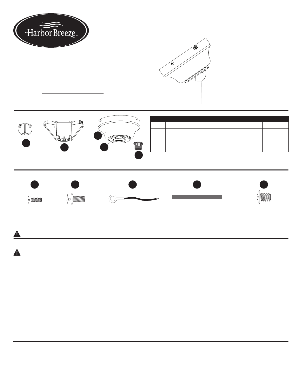
1
3
5
7b
9
8
1. Turno󰀨circuitbreakersandwallswitchto
the fan supply line leads.
DANGER: Failure to disconnect the
power supply prior to installation may
result in serious injury or death.
2. With the mounting bracket (B) resting
inside the canopy (C), partially install two
mounting bracket screws (EE) into the
two holes surrounded by the J-slots in the
canopy (C). Then, remove the mounting
bracket (B) from the canopy (C).
3. Using the screws and washers provided
withtheoutletbox(notincluded),secure
themountingbracket(B)toa“Ceiling
FanRated”outletbox.Theopeningof
mounting bracket (B) should open toward
theoor.
4. Slide the accessory downrod (sold
separately) into the yoke of the ceiling fan.
Install the accessory downrod according
to the instruction manual included with the
ceiling fan.
5. If using this item on an angled ceiling,
snap out the perforated section of the
canopy cover (D).
6. Slide the canopy (C) of your choice and
the ball (A) onto the accessory downrod.
Note: Ball (A) must be positioned with the
holes near the top of the downrod.
2
B
B
C
BEE
A
A
A
DD
D
A
C
CC
BB
BB
DD
CC
AA
E
10
6
7a
Printed in China
7a. If using a 3/4-inch diameter
accessory downrod, attach the ground
wire (CC) to the smaller hole in the
accessory downrod using the ground
screw (BB). Then slide the pin (DD)
into the two large holes at the top of the
downrod.
7b. If using a 1/2-in. diameter downrod,
slide the ball adapter (E) onto the
accessory downrod and down into the
center of the ball (A). Then, attach the
ground wire (CC) to the small hole in
the top of the accessory downrod with
the ground screw (BB). Align the large
holes in the ball adapter (E) with the
large holes in the top of the accessory
downrod, then slide pin (DD) through
larger holes in the ball adapter (E) and
downrod.
8. Raise the ball (A) to the top of accessory
downrod, aligning hole in the ball (A)
with set screw hole at top of downrod.
This will allow the pin (DD) to fall into
the proper slot in the top of the ball (A).
Then, secure the ball (A) to the top of
the accessory downrod using the set
screw (AA).
9. Lift the ball (A) along with the fan into
the opening in the mounting bracket (B).
Align one of the slots in the ball (A) with
tab in the mounting bracket (B).
DANGER: Failure to align a slot in
the ball (A) with the tab in the mounting
bracket (B) may cause fan to wobble or
fall, which could result in serious injury
or death.
10. Align the canopy (C) over the
loose mounting bracket screws (EE)
preassembled on the mounting bracket
(B) in Step 2. Then, twist canopy (C) to
lock. Insert two more mounting bracket
screws (EE) into the round holes of the
canopy (C). Tighten all four mounting
bracket screws (EE).
Opening
Accessory
Downrod
Yoke
Tab
Slot
Note: Thisitemwasdesignedforusewithanexistingceilingfan.Itwillbenecessarytopurchasealongerdownrodinordertoinstallthefantoavaultedceiling.
The parts included with this item will be used instead of similar parts included with your fan.
4
Hole
9168•101716
B
EE
C
2
Top view
J-slot
DD
Hole