manuals.online logo
Brands
  1. Home
  2. •
  3. Brands
  4. •
  5. Harman Kardon
  6. •
  7. CD Player
  8. •
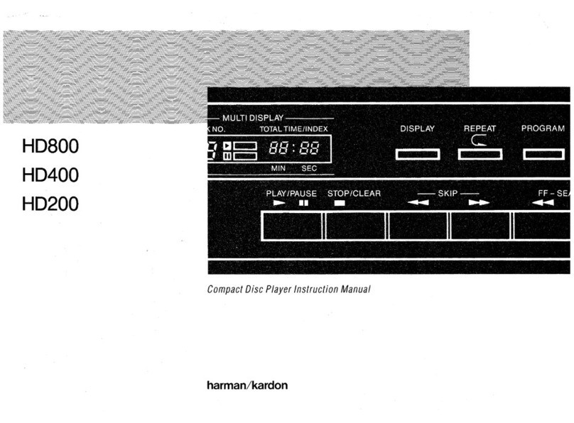
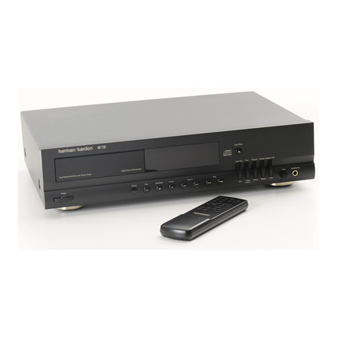
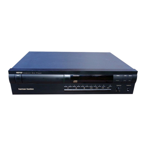
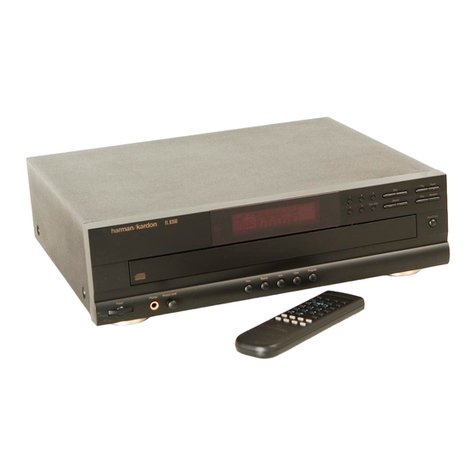
  9. Harman Kardon MAS 101 User manual

Harman Kardon MAS 101 User manual

Music system
Service Manual
MAS 101/102/111 CD
CONTENTS
1. Specification ………………………………………………………………………………………………………….….1
2. Packing …………………………………………………………………………………………………………..………3
3. Front panel information ………………………………………………………………………………………………...4
4. Rear panel information …………………………………………………………………………………………………5
5. Remote control information ……………………………………………………………………………………………6
6. Block diagram …………………………………………………………………………………………………………...8
7. Wiring diagrams ………………………………………………………………………………………………………...9
8. IC spec ……………………………………………………………………………………………………………..…..10
9. Printed circuit boards ……………………………………………………………………………………………..…..87
10. Schematic diagram ………………………………………………………………………………………………..….97
11. Exploded view …………………………………………………………………………………………………….…108
12. Electrical parts list ……………………………………………………………………………………………………110
1
MAS SySteM
Specifications
System
Power output 65 watts per channel, 20Hz – 20kHz,THD <0.07%, into 6 ohms, both channels driven
Bandwidth 20Hz – 35kHz, –3dB
System frequency response 20Hz – 20kHz, ±0.5dB
Signal-to-noise ratio, A-weighted 90dB (Analog inputs), 96dB (Digital inputs)
Channel separation ≥65dB
Crosstalk between sources ≥70dB
Line-level input sensitivity at 1kHz 250mV RMS, ±1dB
Phono MM input sensitivity at 1kHz 7.5mV
Loudspeakers
Low-frequency transducers Two 130mm honeycomb composite drivers, ported
High-frequency transducers Two 25mm MMD
®
domes, shielded
Nominal impedance 8 ohms
Sensitivity (2.83V/1m) 85dB
Frequency response 60Hz – 25kHz (–3dB)
Crossover frequency 2200Hz
FM Tuner Section
Frequency range 87 – 108.0MHz
Usable sensitivity IHF 1.3µV/13.2dBf
Frequency response 10Hz to 15.3kHz
Signal-to-noise ratio mono/stereo 68/65dB
Distortion mono/stereo 0.15/0.3%
Stereo separation 35dB @ 1kHz, 100% deviation @ 65dBf
Selectivity ±300kHz; 65dBF
Image rejection 80dB
IF rejection 90dB
Tuner output level 1kHz, ±50kHz, Dev 500mV
Number of presets 30
RDS capability PS (program service), RT (dynamic radio text)
0257CSK - HK MAS 101-102-111 OM v6.indd 18 08/12/10 9:44:52
ENGLISH
MAS SySteM
Specifications
CD Section
Disc compatibility CD, CD-R, CD-RW, MP3, WMA
THD+N (20Hz – 20kHz) <0.025%
Frequency response 20Hz to 20kHz, 0dB ±0.5
Channel separation ≥65dB
Signal-to-noise ratio “A”WTG >96dBr; 22kHz filter > 94dBr
General
Power requirement AC 230V/50Hz (MAS 101/MAS 111); AC 120V/60Hz (MAS 102)
Power consumption <1W full standby (clock not activated); <2W standby (clock activated);
150W maximum (both channels driven)
Operating temperature 0°C to 40°C
Dimensions (H x W x D) Controller: 90mm x 240mm x 240mm (3-9/16" x 9-7/16" x 9-7/16")
Amplifier: 90mm x 240mm x 240mm (3-9/16" x 9-7/16" x 9-7/16")
Loudspeakers (each, with grille): 272mm x 181mm x 196mm
(10-23/32" x 7-1/8" x 7-3/4")
Weight System 13.9kg (30,5lb)
Controller 2.0kg (4,4lb)
Amplifier 2.8kg (6,3lb)
Loudspeakers (each): 4.4kg (9,8lb)
0257CSK - HK MAS 101-102-111 OM v6.indd 19 08/12/10 9:44:52
2
harman/kardon
MAS101 MAS102 MAS111
2
2
1
3
5BOX
SET
EPE
1
2
3
4
5
NO DESCRIPTION PARTS NO. Q,ty
1
2
1
4
1
8250 503B 0000
3320 0805 0352
SET
EPE
BOX
8150 5030 0000
8150 5011 0000
REMOTE CONTROL ASS'Y
EPE
CARDBOARD CORNER 4
CARDBOARD CORNER
3
4
0
2
7
8
4
9
6
5
A
1 3
ENGLISH
MAS SySteM
Front-Panel Controls
Controller and Amplifier
Note: Controls are the same for all models.
The MAS systems use touch-sensitive controls.To use a control, tap gently on its lit icon.
NOTE:Controls are the same for all models.
0
Power:Turns the MAS system on or places it in Standby mode.To completely power
off the unit, unplug the power supply.
1
Message Display:The time and messages are displayed in this two-line text display.
2
CD Slot:Load compatible discs here.
3
Skip/Scan Forward/Reverse:These buttons function differently, depending on the
current source:
iPod, CD or USB
•
:Press and release to skip to the next track. Press the Reverse
button twice to skip to the previous track. Press and hold a button to scan
forward or reverse within a track.
Radio
•
:Press and release a button to select the next higher or lower programmed
preset station. Press and hold a button to scan to the next available higher or
lower station.When you release the button, the tuner continues to scan until it
finds a station of acceptably strong signal quality, and then it stops. To stop the
scan before a station is found, press the button while the tuner is scanning.
4
Play/Pause:Each tap toggles between the Play and Pause functions.
5
Stop:Fully stops playback.
6
Eject:When a CD is loaded, tap here to eject it.
7
USB Port A:Connect a compatible USB device here to enjoy playback of audio MP3
orWMA files. Although most USB flash and hard-disk drives in the FAT32 file format,
as well as many MP3 players, are compatible with the MAS system, due to the wide
variety of manufacturers, playback cannot be guaranteed. Do not connect an iPod
or iPhone to this port. Do not connect a personal computer or any peripherals to this
port.
8
Line-In Jack (Line Input):Connect a stereo 3.5mm male-to-male cable (not
included) to the headphone or line-level output on a portable player or other device.
9
Headphone Jack:Outputs a stereo signal for private listening through most
headphones that are equipped with a stereo 3.5mm plug.
A
Volume Control:Increases or decreases the volume.
0257CSK - HK MAS 101-102-111 OM v6.indd 5 08/12/10 9:44:49
5
c
d
d
h
e
f
a
l
k
b
j
i
g
MAS SySteM
Rear-panel connections
Controller
0
FM Antenna Terminal:Connect the included FM antenna wire here.
1
DAB Antenna Terminal (MAS 111 Only):Connect the included DAB antenna wire
lead here to enjoy programming from digital DAB, DAB+ orT-DMB-Audio radio
stations available in your area.
2
USB Port B: Connect a compatible USB device here to enjoy playback of audio MP3
orWMA files. Although most USB flash and hard-disk drives in the FAT32 file format,
as well as many MP3 players, are compatible with the MAS system, due to the wide
variety of manufacturers, playback cannot be guaranteed. Do not connect an iPod
or iPhone to this port. Do not connect a personal computer or any peripherals to this
port.
3
Optical 1/2 and Coaxial 1/2 Digital Audio Inputs:Connect a source device’s
optical or coaxial digital audio output to the corresponding input. Only the
uncompressed PCM format is supported.
4
TV and AUX Analog Audio Inputs:Connect the analog audio outputs of a tele-
vision or any source device to enjoy playback through the high-performance MAS
system.
5
Phono Input:Connect the outputs of a moving-magnet (MM) type turntable to this
input. Do not connect any other type of turntable to this input, and do not connect
the outputs of an MM-type turntable to any other analog audio inputs on the MAS
system without using a phono preamp, available separately from many electronics
stores.
6
The Bridge IIIP Input:To enjoy playback of audio materials stored on a compatible
iPod (see page 4), connectThe Bridge IIIP. Make sure the insert forThe Bridge IIIP is
installed, and install the appropriate dock adapter for your iPod within the insert, as
shown in Figure 1 on page 10.
7
Analog Audio Outputs:Connect these outputs to the analog audio inputs of an
audio recorder. When a source connected to the MAS system is playing, the signal will
be available at these outputs for recording. IMPORTANT:The Analog Audio Outputs
will mute when the Mute button on the remote is pressed. See page 9.
8
Coaxial Digital Audio Output:Connect this output to the coaxial digital audio
input of a digital audio recorder. When the following sources are playing, the signal
will be available at this output for recording: CD, USB Ports A/B, Coaxial 1/2, Optical
1/2.The following sources are not available at this output: FM/DAB, TV, Aux, Phono,
The Bridge IIIP.
NOTES:
The MAS system can convert analog sources to the digital domain, or digital
•
sources to the analog domain for recording.
It is the user’s responsibility to comply with all laws pertaining to the
•
copying of audio materials.
9
Output to Amplifier:Connect the included ribbon cable to this connector and to
the corresponding connector on the MAS amplifier. This cable passes audio signals
from the controller to the amplifier, and it transfers DC power from the amplifier
to the controller. If this cable is ever damaged, do not use it, and contact Harman
Kardon for a replacement.
A
RS-232 Serial Port:This port is used only for system upgrades. Do not connect it to
any devices unless instructed to do so at the time a system upgrade is released.
B
Update Switch:This switch is used only for system upgrades. Leave it in the“N”
position for normal operation unless instructed to switch it to the“U”position to
install a system update.
0257CSK - HK MAS 101-102-111 OM v6.indd 6 08/12/10 9:44:49
6
MAS SySteM
Remote control functions
Sleep
Display
Settings
Time
Enter
Program/Memory
Power
Source Selectors
Info
Back
K/LM/N Navigation
Clear
Eject
FM Mode
Transport Controls
Preset/Folder +/–
Numeric keys
–10 numeric Key
Check Random
Auto Store
Volume +/–
Mute
+10 numeric Key
Power:Turns the MAS system on or off. To completely power off the unit, unplug the
power supply.
Sleep:Each press increases the time until turn-off, from 10 to 90 minutes, in increments
of 10 minutes.The next press after the 90 minutes setting turns off the Sleep function.
Source Selectors:Selects a source input. Each press of the Line In or Digital In button
toggles among the available analog (Line Input on right-side panel;TV, AUX or Phono
Input on rear panel) or digital audio inputs (Coaxial 1 or 2, Optical 1 or 2), respectively.
Press the iPod button to select an iPod docked inThe Bridge IIIP.
Display:Adjusts the brightness of the message display. Each time the button is pressed
and held for one second, the message display brightness will cycle between full, half and
off.When the display is off while the system is turned on, the LEDs inside theVolume
knob and behind the front-panel function buttons will remain lit to remind you that the
system is still on.
Settings:Accesses menus for Speaker Setup (tone controls),Time Setup (clock), Alarm
Setup, System Version and System Reset. See the Operation section for more information.
Back:Returns to previous menu level.
Info:Displays the status of the current source:
Radio
•
:When FM band is in use, each press of the button toggles between the PS
(Program Service) and RT (RadioText) RDS information, if available. When a DAB
radio station is playing (MAS 111 only), press this button to access the menu system
for the DAB tuner. See pages 13 and 14 for more information.
Audio CD
•
:Displays CDText information, if available. Each press of the button displays
the following items: Song, Artist, Album.
USB or Data CD
•
:Scrolls all ID3 tag information for current source, if available. Each
press of the button displays the individual items Song, Artist, Album, File type and
Folder, and then goes back to scrolling. If ID3 tags are not available, the file name will
appear.
Time:Displays elapsed track time for the current Audio CD (no effect on data CDs or
other sources). Each additional press changes the display as follows: remaining track
time, elapsed disc time, remaining disc time then back to elapsed track time.
K
/
LM
/
N
Navigation buttons: Use the
M
and
N
buttons to scroll forward and reverse
through the Settings Menus, or through lists of content, and press the Enter button to
make selections. Press the Back button to return to the previous menu or content level.
Enter:Selects a menu item, or saves setting changes and returns to the previous menu
level.
0257CSK - HK MAS 101-102-111 OM v6.indd 8 08/12/10 9:44:49
7
ENGLISH
MAS SySteM
Remote control functions
Clear:Clears the current preset station or a playlist entry.
Radio
•
:To delete the current preset station, press the Clear button while it is playing.
Playlist
•
:While programming a playlist, press the Clear button to delete the track just
entered. After the playlist has been saved by pressing the Stop button, press the Clear
button to delete the entire playlist.To delete a single track, stop play, press the Check
button repeatedly until the desired track appears and press the Clear button. Press
the Play or Stop button to exit the Check mode.
Program/Memory:Used to program playlists and radio presets.
Radio
•
:If the current station has not been programmed into a preset, press Program/
Memory and press the Enter button to store the station at the current preset number,
or use the numeric keys to enter a different preset number. The new preset will
overwrite the existing one.
USB or CD (Audio or Data)
•
:Press the Program button to begin Program Mode. Add
tracks to the playlist by using the Skip/Scan Transport Controls or the numeric keys
to select the track, then press the Program button to enter the selection. Add up to
30 files. Press Play to play the playlist, or Stop to save the playlist without playing it.
During playback, the order of the track in the playlist will appear on the left, with the
disc’s track number to the right. See page 14 and 15.
Check:After a playlist has been programmed and play has been stopped, each press of
the Check button displays the tracks in the playlist.
Eject:When a CD is loaded, press this button to eject it.
FM Mode:Used with FM radio, each press toggles between Stereo and Monaural
playback.
Auto Store:Scans through all frequencies, searching for stations with acceptably strong
signal quality, and stores them as presets.
Random: Each press turns Random playback mode (shuffle) on or off. This mode plays
the tracks of the current disc or drive in random order.
Transport Controls
Track Skip Up/Down (iPod, CD or USB):Press and release the Next/Previous
skip buttons to skip to the next track, or the beginning of the current track. Press the
Previous Skip button twice to skip to the previous track.
Scan Forward/Reverse:These buttons function differently, depending on which
source has been selected:
iPod, CD or USB
•
: Press and hold a button to scan forward or reverse within a
track.
Radio:
•
Press and release a button to tune to the next higher or lower frequency
by one increment/decrement. Press and hold a button to scan quickly through
the frequencies for next available station. Press the same button again to stop
scanning.
Play/Pause: Each tap toggles between the Play and Pause functions.
Stop: Fully stops playback.
Preset/Folder +/–:Selects a preset station or folder on a USB or data CD.
Radio
•
: Each press changes to the next or previous preset station, if any have been
programmed.
USB or Data CD
•
: Press once to open the current folder. Each additional press changes
to the next or previous folder. After 3 seconds, the first track in the new folder will
begin playing.
Mute: Press to temporarily silence the speakers. Press again to restore audio. Muting is
also canceled if the MAS system is turned off.
NOTE: Pressing the Mute button also mutes the Analog Audio Outputs. See page 6.
Volume +/–: Increases or decreases the volume. Press and hold to change the volume
more quickly.
Numeric keys:Used to enter track numbers, radio stations or preset numbers, or while
adjusting the clock and alarm times.
–10 and +10 numeric Key: Used with a USB device or CD to quickly advance through a
large number of tracks. Each press of these keys changes to the next or previous track in
increments of 10.
0257CSK - HK MAS 101-102-111 OM v6.indd 9 08/12/10 9:44:50
5
5
4
4
3
3
2
2
1
1
D D
C C
B B
A A
MAS111 Head UnitBlock Diagram
Disc
Drive
OPU
LOADER
SLOT IN DRIVER
MOTOR
RELAYUSB Front
USB Back
USB
Inputs
Ali
M5673
Servo
USB 1.1
iPod Connector
iPod LMV
832 Main
CPU
Antenna
RF
DAB
RF
DAB/DAB+/DMB
Venice 7.1
Frontier Silicon
I C
2
Digital Coax 2
Coax 1
Optical 1
Optical 2
Inputs
RF Antenna
RF CAN
Tuner
C
2
I
TV
Inputs
Line
AUX
Phono MM
Line In
dB30
RIAA
BD3841FS
Line_In_1
Line_In_2
Line_In_3
Line_In_4
Line_In_5
Line_In_6
Line_In_7
CS42516
2608
NJM
NJM
2608
Spdif_In6
AINL
AINR
Spdif_In5
Spdif_In4
Spdif_In3
Spdif_In2
Spdif_In1
Dac1_L
CS48540
DSP
SAI SI
2
_Input_Out
I_Iine_Out
2
S
I_Main_Out
2
S
I_Sub_Out
2
S
TXP
CX
SWITCH
74HC151
Tx
CI
2
2608
NJM
Coax
Out Main Digital
Output
Line
Subwoofer
Headphone
Subwoofer
Out
Line
Headphone
Out
Audio
Out
Out
Out
NJM
2608
HP
AMP
ConnectoionAmp
+3.3V
LDO
+1V
+8V
Control
Circuit
LDO
SPI
C
2
I
MOLEX
IR
Sense
TOUCH
Sense
TOUCH
CPU
Driver
VFD
2
I C/SPI
SPI
+5V
Front
Panel
Dac1_R
Dac2_L
D/A
Dac2_R
Dac3_L
NJM
2608
2608
2608
NJM
NJM
NJM
2608
NJM
2608
UART iPod TX
UART iPod RX
In-R
In-L
Charger GND
Charger +8V
iPod CHECK
HW Identification
iPod_In-L
iPod_In-R
RF
Coaxial_1
Coaxial_2
Optical_1
Optical_2
RF_FM Tuner_L
Tuner_R
SPI RDS
SPI Tuner
iPod_In-R
Jack_In_R
Jack_In_L
iPod_In-L
+
-
-
+
SPDIF_DAB_OUT
SPDIF_ALI_OUT
SPDIF_ALI_OUT
SPDIF_OUT_DIRECT
SPDIF_SW
Coaxial_Out
+
-
Main_Out_R
Main_Out_R
-
+
HP_Out_L
Line_Out_L
Subwoofer_Out
Line_Out_R
HP_Out_R
Out_R
Out_L
-15V
+15V
DGND
AGND
+5V
Relay_Control
Offset_detect
VOL-
VOL+
Mute_Audio
Standby
Drop_detect
iPod CHECK
MM_MC_Sel
SPDIF_SW
IR
AMP_R-
AMP_R+
AMP_L-
AMP_L+
-
Line_Out_L
+
+
+
-
-
Line_Out_R
Subwoofer_Out
Main_Out_L
Main_Out_L
8
CD CORE
RS232 BOARD
MAIN BOARD
DISPLAY BOARD
HEADPHONE
BOARD
TUNER
CN3
10P
CN2
9P
CN1
7P
CN1
16P
CON9
16P
CON2
5P
CON4
16P
CON3
6P
CON10
13P
CON11
7P
CON1
13P
CON7
9P
CON5
10P
CON8
2P
9
Philips Semiconductors Product specification
Hex inverter 74HCU04
FEATURES
•Output capability: standard
•ICC category: SSI
GENERAL DESCRIPTION
The 74HCU04 is a high-speed Si-gate CMOS device and is pin compatible with low power Schottky TTL (LSTTL).
It is specified in compliance with JEDEC standard no. 7A.
The 74HCU04 is a general purpose hex inverter. Each of the six inverters is a single stage
QUICK REFERENCE DATA
GND = 0 V; Tamb =25°C; tr=t
f=6ns
Note
1. CPD is used to determine the dynamic power dissipation (PDin µW):
PD=C
PD ×VCC2×fi+ ∑ (CL×VCC2×fO) where:
fi= input frequency in MHz
fo= output frequency in MHz
CL= output load capacitance in pF
VCC = supply voltage in V
∑(CL×VCC2×fo) = sum of outputs
ORDERING INFORMATION
See
“74HC/HCT/HCU/HCMOS Logic Package Information”
.
FUNCTION TABLE
Note
1. H = HIGH voltage level
L = LOW voltage level
SYMBOL PARAMETER CONDITIONS TYP. UNIT
tPHL/ tPLH propagation delay nA to nY CL= 15 pF; VCC =5V 5 ns
C
Iinput capacitance 3.5 pF
CPD power dissipation capacitance per inverter note 1 10 pF
INPUT OUTPUT
nA nY
L
HH
L
10
Philips Semiconductors Product specification
Hex inverter 74HCU04
PIN DESCRIPTION
PIN NO. SYMBOL NAME AND FUNCTION
1, 3, 5, 9, 11, 13 1A to 6A data inputs
2, 4, 6, 8, 10, 12 1Y to 6Y data outputs
7 GND ground (0 V)
14 VCC positive supply voltage
Fig.1 Pin configuration. Fig.2 Logic symbol. Fig.3 IEC logic symbol.
Fig.4 Functional diagram. Fig.5 Schematicdiagram
(one inverter).
11
12
13
14
1
2
3
5
4
SCL
GND
SDA
WP
VCC
1
2
3
4
8
7
6
5
A0
A1
A2
GND
VCC
WP
SCL
SDA
1
2
3
4
8
7
6
5
VCC
WP
SCL
SDA
A0
A1
A2
GND
VCC
WP
SCL
SDA
A0
A1
A2
GND
1
2
3
4
8
7
6
5
1
2
3
4
8
7
6
5
A0
A1
A2
GND
VCC
WP
SCL
SDA
1
2
3
4
8
7
6
5
A0
A1
A2
GND
VCC
WP
SCL
SDA
8-lead SOIC
8-ball dBGA2
8-lead Ultra-Thin
Mini-MAP (MLP 2x3)
8-lead PDIP
5-lead SOT23
Bottom View Bottom View
8-lead TSSOP
Features
•Low-voltage and Standard-voltage Operation
– 1.8 (VCC = 1.8V to 5.5V)
•Internally Organized 256 x 8 (2K)
•Two-wire Serial Interface
•Schmitt Trigger, Filtered Inputs for Noise Suppression
•Bidirectional Data Transfer Protocol
•1 MHz (5V), 400 kHz (1.8V, 2.5V, 2.7V) Compatibility
•Write Protect Pin for Hardware Data Protection
•8-byte Page (2K) Write Modes
•Partial Page Writes Allowed
•Self-timed Write Cycle (5 ms max)
•High-reliability
– Endurance: 1 Million Write Cycles
– Data Retention: 100 Years
•8-lead PDIP, 8-lead JEDEC SOIC, 8-lead Ultra Thin Mini-MAP (MLP 2x3), 5-lead SOT23,
8-lead TSSOP and 8-ball dBGA2 Packages
•Lead-free/Halogen-free
•Available in Automotive
•Die Sales: Wafer Form, Tape and Reel and Bumped Wafers
Description
The AT24C02B provides 2048bits of serial electrically erasable and programmable
read-only memory (EEPROM) organized as 256 words of 8bits each. The device is
optimized for use in many industrial and commercial applications where low-power
and low-voltage operation are essential. The AT24C02B is available in space-saving
8-lead PDIP, 8-lead JEDEC SOIC, 8-lead UltraThin Mini-MAP (MLP 2x3),5-lead
SOT23, 8-lead TSSOP, and 8-ball dBGA2 packages and is accessed viaaTwo-wire
serial interface. In addition, the AT24C02B is available in 1.8V (1.8V to 5.5V) version.
Note: For use of 5-lead SOT23, the
software A2, A1, and A0 bits in
the device address word
must be set to zero to prop-
erly communicate.
Table 0-1. Pin Configuration
Pin Name Function
A0 - A2 Address Inputs
SDA Serial Data
SCL Serial Clock Input
WP Write Protect
GND Ground
VCC Power Supply
Two-wire
Serial EEPROM
2K (256 x 8)
AT24C02B
5126H–SEEPR–8/07
15
17
18

Other manuals for MAS 101

1

This manual suits for next models

2

Other Harman Kardon CD Player manuals

Harman Kardon TL8500 User manual

Harman Kardon

Harman Kardon TL8500 User manual

Harman Kardon HD800 User manual

Harman Kardon

Harman Kardon HD800 User manual

Harman Kardon DVD 5 User manual

Harman Kardon

Harman Kardon DVD 5 User manual

Harman Kardon HD7225 User manual

Harman Kardon

Harman Kardon HD7225 User manual

Harman Kardon HD7525 User manual

Harman Kardon

Harman Kardon HD7525 User manual

Harman Kardon HD7400 User manual

Harman Kardon

Harman Kardon HD7400 User manual

Harman Kardon HD710 User manual

Harman Kardon

Harman Kardon HD710 User manual

Harman Kardon HD750 User manual

Harman Kardon

Harman Kardon HD750 User manual

Harman Kardon HD710 User manual

Harman Kardon

Harman Kardon HD710 User manual

Harman Kardon HD200IBK User manual

Harman Kardon

Harman Kardon HD200IBK User manual

Harman Kardon HD 980 User manual

Harman Kardon

Harman Kardon HD 980 User manual

Harman Kardon HD7625 User manual

Harman Kardon

Harman Kardon HD7625 User manual

Harman Kardon HD7500 User manual

Harman Kardon

Harman Kardon HD7500 User manual

Harman Kardon DVD 31 User manual

Harman Kardon

Harman Kardon DVD 31 User manual

Harman Kardon FL 8380 User manual

Harman Kardon

Harman Kardon FL 8380 User manual

Harman Kardon HD710 User manual

Harman Kardon

Harman Kardon HD710 User manual

Harman Kardon HD720 User manual

Harman Kardon

Harman Kardon HD720 User manual

Harman Kardon HD 990 User manual

Harman Kardon

Harman Kardon HD 990 User manual

Harman Kardon HD7300 User manual

Harman Kardon

Harman Kardon HD7300 User manual

Harman Kardon HD7325 User manual

Harman Kardon

Harman Kardon HD7325 User manual

Harman Kardon HD200 User manual

Harman Kardon

Harman Kardon HD200 User manual

Harman Kardon HD 3700 User manual

Harman Kardon

Harman Kardon HD 3700 User manual

Harman Kardon DVD1 User manual

Harman Kardon

Harman Kardon DVD1 User manual

Harman Kardon HD 950 User manual

Harman Kardon

Harman Kardon HD 950 User manual

Popular CD Player manuals by other brands

Aiwa XP-577 Service manual

Aiwa

Aiwa XP-577 Service manual

Yamaha CDX-730 owner's manual

Yamaha

Yamaha CDX-730 owner's manual

Philips AZ1407/17 Instructions for use

Philips

Philips AZ1407/17 Instructions for use

Advance Paris X-D500 quick start

Advance Paris

Advance Paris X-D500 quick start

Sony DVP-FX780 operating instructions

Sony

Sony DVP-FX780 operating instructions

Marantz SA-17S1 user guide

Marantz

Marantz SA-17S1 user guide

Cayin MINI-CD MK2 user manual

Cayin

Cayin MINI-CD MK2 user manual

Philips AZ1300 Specifications

Philips

Philips AZ1300 Specifications

Panasonic SL-CT830 operating instructions

Panasonic

Panasonic SL-CT830 operating instructions

Philips Soundmachine AZ100B user manual

Philips

Philips Soundmachine AZ100B user manual

Memorex MP3848 user guide

Memorex

Memorex MP3848 user guide

Sony Discman D-265 operating instructions

Sony

Sony Discman D-265 operating instructions

Gold Note CD-7 owner's manual

Gold Note

Gold Note CD-7 owner's manual

Tascam CD-A700 Technical documentation

Tascam

Tascam CD-A700 Technical documentation

Rotel RCD-02 Technical manual

Rotel

Rotel RCD-02 Technical manual

Marantz SA7001KI Service manual

Marantz

Marantz SA7001KI Service manual

Philips psa[cd ACT500 Specifications

Philips

Philips psa[cd ACT500 Specifications

Onkyo DX-C730 instruction manual

Onkyo

Onkyo DX-C730 instruction manual

manuals.online logo
manuals.online logoBrands
  • About & Mission
  • Contact us
  • Privacy Policy
  • Terms and Conditions

Copyright 2025 Manuals.Online. All Rights Reserved.