Harmonic MAXLink HOA 7100 Series User manual

HOA 7100
MAXLink™
Optical Amplifier
Product Manual
Manual Part No.: 700-0051982
Rev C
April 2005

HOA 7100 MAXLink Optical Amplifier Product Manual
Copyright © 2004 Harmonic Inc.
Copyright 2004 Harmonic Inc.
Harmonic continues to improve and enhance all product designs. Specifications are subject to change without notice. Harmonic and logo design,
eXchange, MAXLink, METROLink, NETWatch, PWRBlazer, TRANsend, and “Redefining the Network” are trademarks of Harmonic Inc. YAGLink
and PWRLink are registered trademarks of Harmonic Inc. All other names are trademarks or registered trademarks of their respective owners.

HOA 7100 MAXLink Optical Amplifier Product Manual Rev C (4/05) i
Table of Contents
Chapter 1 Overview
1.1 About This Manual . . . . . . . . . . . . . . . . . . . . . . . . . . . . . . . . . . . . . . . . . . . . . . 1-1
1.2 Product Manual Applicability . . . . . . . . . . . . . . . . . . . . . . . . . . . . . . . . . . . . . 1-1
1.3 Product Description . . . . . . . . . . . . . . . . . . . . . . . . . . . . . . . . . . . . . . . . . . . . . . 1-1
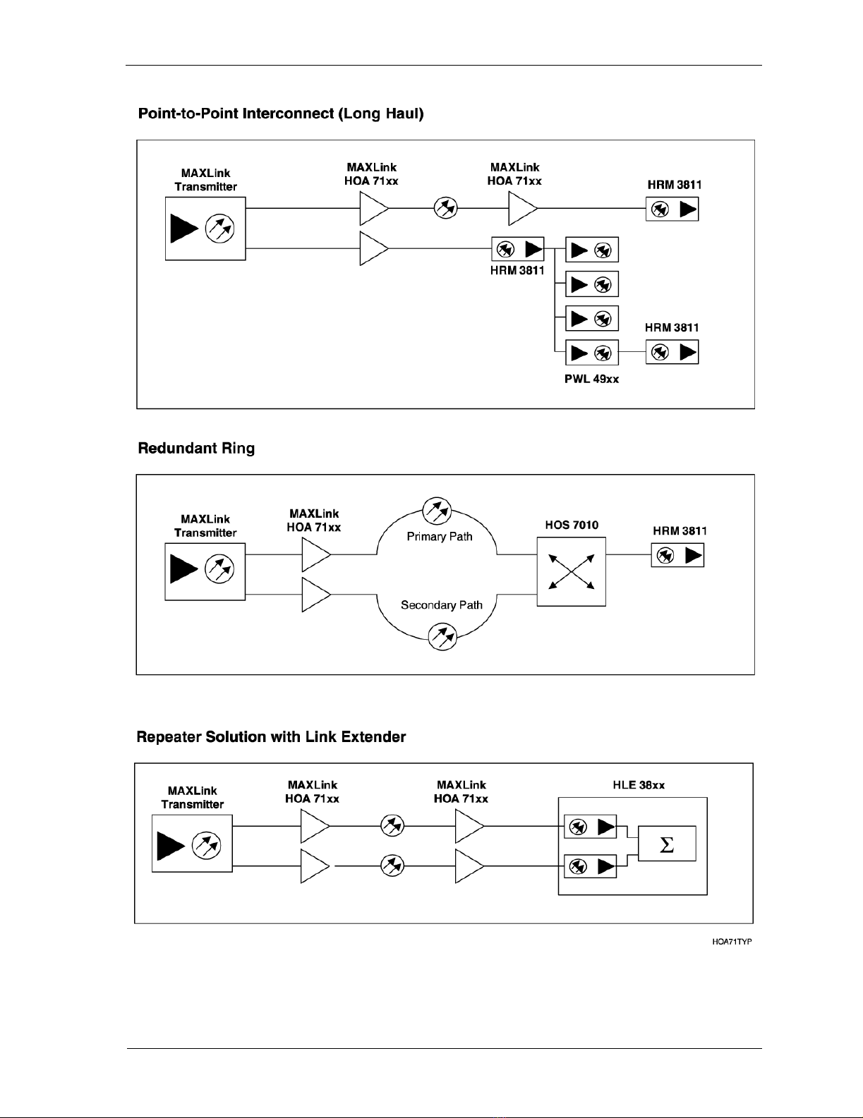
1.4 Product Applications. . . . . . . . . . . . . . . . . . . . . . . . . . . . . . . . . . . . . . . . . . . . . 1-2
Chapter 2 Front Panel Interface
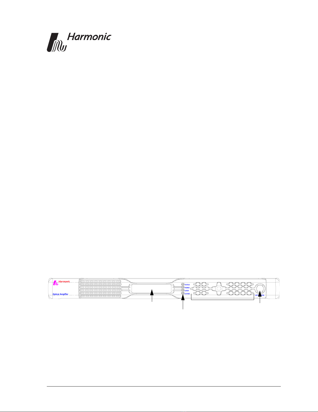
2.1 Front Panel Features . . . . . . . . . . . . . . . . . . . . . . . . . . . . . . . . . . . . . . . . . . . . . 2-1
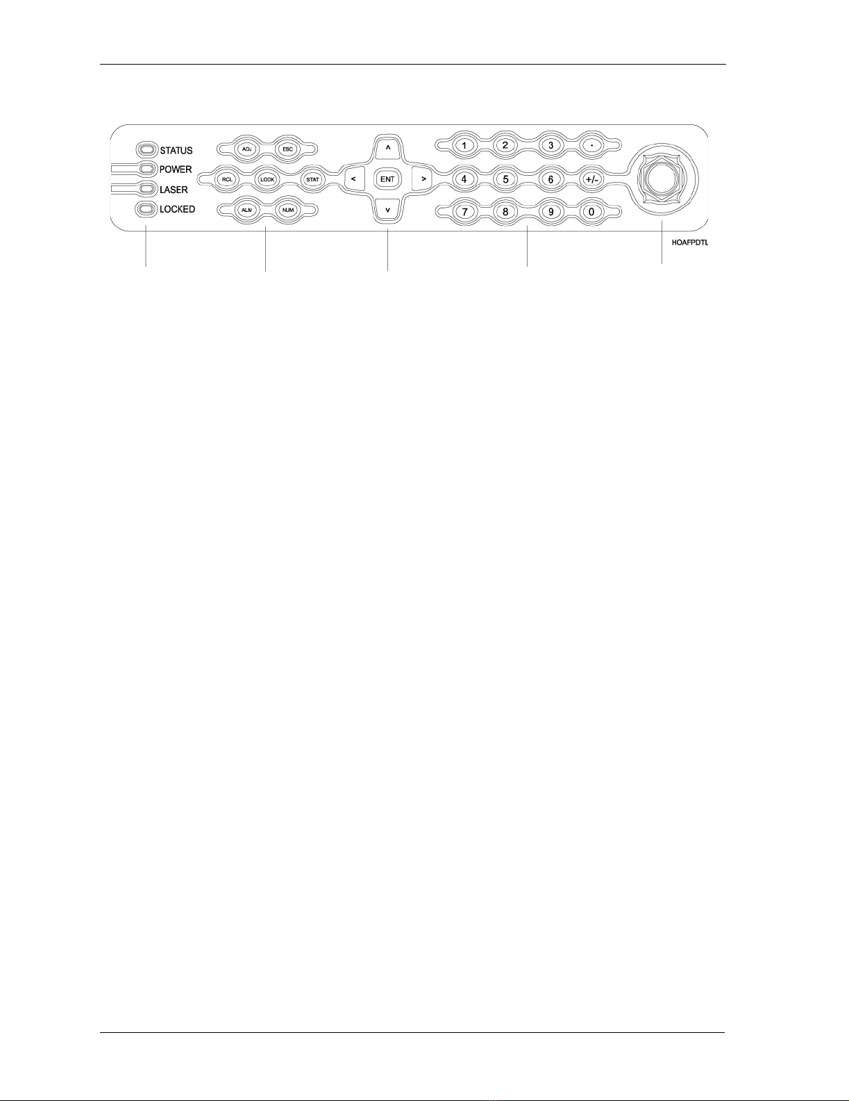
2.1.1 Front Panel LEDs . . . . . . . . . . . . . . . . . . . . . . . . . . . . . . . . . . . . . . . . . . 2-2
2.1.2 Function Keys . . . . . . . . . . . . . . . . . . . . . . . . . . . . . . . . . . . . . . . . . . . . 2-2
2.1.3 Navigation Keys . . . . . . . . . . . . . . . . . . . . . . . . . . . . . . . . . . . . . . . . . . 2-3
2.1.4 Numeric Keypad . . . . . . . . . . . . . . . . . . . . . . . . . . . . . . . . . . . . . . . . . . 2-3
2.2 The Menu System. . . . . . . . . . . . . . . . . . . . . . . . . . . . . . . . . . . . . . . . . . . . . . . . 2-3
2.2.1 HOA Status Menu . . . . . . . . . . . . . . . . . . . . . . . . . . . . . . . . . . . . . . . . . 2-4
2.2.2 HOA Adjustment Menu . . . . . . . . . . . . . . . . . . . . . . . . . . . . . . . . . . . . 2-5
2.2.3 HOA Adjustment Options . . . . . . . . . . . . . . . . . . . . . . . . . . . . . . . . . . 2-5
2.2.4 HOA Alarms Menu . . . . . . . . . . . . . . . . . . . . . . . . . . . . . . . . . . . . . . . . 2-6
Chapter 3 Installing the HOA 7100 Optical Amplifier
3.1 Receiving and Inspecting . . . . . . . . . . . . . . . . . . . . . . . . . . . . . . . . . . . . . . . . . 3-1
3.2 Tools and Accessories . . . . . . . . . . . . . . . . . . . . . . . . . . . . . . . . . . . . . . . . . . . . 3-2
3.3 Cable Requirements. . . . . . . . . . . . . . . . . . . . . . . . . . . . . . . . . . . . . . . . . . . . . . 3-2
3.4 Rear Panel Diagrams . . . . . . . . . . . . . . . . . . . . . . . . . . . . . . . . . . . . . . . . . . . . . 3-3
3.5 Precautions . . . . . . . . . . . . . . . . . . . . . . . . . . . . . . . . . . . . . . . . . . . . . . . . . . . . . 3-4
3.6 Mounting the HOA 7100. . . . . . . . . . . . . . . . . . . . . . . . . . . . . . . . . . . . . . . . . . 3-7
3.6.1 Mounting the HOA 7100 in a 19-inch Cabinet . . . . . . . . . . . . . . . . . 3-7
3.7 Connecting Power . . . . . . . . . . . . . . . . . . . . . . . . . . . . . . . . . . . . . . . . . . . . . . . 3-7
3.7.1 Connecting AC Power . . . . . . . . . . . . . . . . . . . . . . . . . . . . . . . . . . . . . 3-7
3.7.2 Connecting DC Power . . . . . . . . . . . . . . . . . . . . . . . . . . . . . . . . . . . . . 3-8
3.8 Connecting the Optical Fiber Cables. . . . . . . . . . . . . . . . . . . . . . . . . . . . . . . . 3-8
3.9 Connecting the Alarm Relay. . . . . . . . . . . . . . . . . . . . . . . . . . . . . . . . . . . . . . . 3-9
3.10 Connecting the TTL Alarm Cable . . . . . . . . . . . . . . . . . . . . . . . . . . . . . . . . . 3-10
3.11 Connecting the Ethernet Cable. . . . . . . . . . . . . . . . . . . . . . . . . . . . . . . . . . . . 3-10
3.12 Assigning IP Addresses. . . . . . . . . . . . . . . . . . . . . . . . . . . . . . . . . . . . . . . . . . 3-10
3.13 Checking the LEDs for Normal Operation. . . . . . . . . . . . . . . . . . . . . . . . . . 3-11
Chapter 4 Web Interface
4.1 Requirements . . . . . . . . . . . . . . . . . . . . . . . . . . . . . . . . . . . . . . . . . . . . . . . . . . . 4-1
4.2 MAXLink HTTP Access Control . . . . . . . . . . . . . . . . . . . . . . . . . . . . . . . . . . . 4-2
4.3 Accessing and Using the Web Interface . . . . . . . . . . . . . . . . . . . . . . . . . . . . . 4-3
4.4 Adjusting the Amplifier . . . . . . . . . . . . . . . . . . . . . . . . . . . . . . . . . . . . . . . . . . 4-5
4.5 Web Interface Tips . . . . . . . . . . . . . . . . . . . . . . . . . . . . . . . . . . . . . . . . . . . . . . . 4-6
Chapter 5 Connecting the HOA 7100 to an NMS

Table of Contents
ii Copyright © 2004 Harmonic Inc.
Chapter 6 Maintenance and Troubleshooting
6.1 Cleaning Fiber Optic Connectors. . . . . . . . . . . . . . . . . . . . . . . . . . . . . . . . . . . 6-1
6.1.1 Cleaning Patch Cord or Pigtail Fiber Optical Connectors . . . . . . . . 6-2
6.1.2 Cleaning MAXLink Amplifier Optical Connectors . . . . . . . . . . . . . 6-2
6.2 Alarms . . . . . . . . . . . . . . . . . . . . . . . . . . . . . . . . . . . . . . . . . . . . . . . . . . . . . . . . . 6-3
6.3 Troubleshooting . . . . . . . . . . . . . . . . . . . . . . . . . . . . . . . . . . . . . . . . . . . . . . . . . 6-4
6.4 In Case of Problems . . . . . . . . . . . . . . . . . . . . . . . . . . . . . . . . . . . . . . . . . . . . . . 6-5
6.5 Disclaimer . . . . . . . . . . . . . . . . . . . . . . . . . . . . . . . . . . . . . . . . . . . . . . . . . . . . . . 6-5
6.6 Warranty Summary . . . . . . . . . . . . . . . . . . . . . . . . . . . . . . . . . . . . . . . . . . . . . . 6-6
6.7 Limitations of Warranty . . . . . . . . . . . . . . . . . . . . . . . . . . . . . . . . . . . . . . . . . . 6-6
6.8 Exclusive Remedies . . . . . . . . . . . . . . . . . . . . . . . . . . . . . . . . . . . . . . . . . . . . . . 6-6
Appendix A Technical Specifications
A.1 Optical Output . . . . . . . . . . . . . . . . . . . . . . . . . . . . . . . . . . . . . . . . . . . . . . . . . . A-1
A.2 User Interface . . . . . . . . . . . . . . . . . . . . . . . . . . . . . . . . . . . . . . . . . . . . . . . . . . . A-2
A.3 Electrical . . . . . . . . . . . . . . . . . . . . . . . . . . . . . . . . . . . . . . . . . . . . . . . . . . . . . . . A-2
A.4 Environmental . . . . . . . . . . . . . . . . . . . . . . . . . . . . . . . . . . . . . . . . . . . . . . . . . . A-2
A.5 Physical . . . . . . . . . . . . . . . . . . . . . . . . . . . . . . . . . . . . . . . . . . . . . . . . . . . . . . . . A-2
A.6 Laser Radiation Warning . . . . . . . . . . . . . . . . . . . . . . . . . . . . . . . . . . . . . . . . . A-3
A.7 Agency Certifications . . . . . . . . . . . . . . . . . . . . . . . . . . . . . . . . . . . . . . . . . . . . A-3
A.8 Management Parameters . . . . . . . . . . . . . . . . . . . . . . . . . . . . . . . . . . . . . . . . . A-4
Appendix B Harmonic Inc. – Offices

HOA 7100 MAXLink Optical Amplifier Product Manual Rev C (4/05) 1–1
1
Overview
1.1 About This Manual
This instruction manual is a complete guide to installing and operating the
one Rack Unit (1 RU) HOA 7100 MAXLink Optical Amplifier. Please read the
entire manual before beginning installation.
• Chapter 1 gives general information about the HOA 7100 MAXLink
Optical Amplifier.
• Chapter 2 describes the front panel interface.
• Chapter 3 describes the installation procedures.
• Chapter 4 describes the web interface.
• Chapter 5 tells you how to connect to a network management system.
• Chapter 6 describes maintenance and what to do in the event of problems.
• Appendix A provides complete technical specifications.
• Appendix B provides a list of Harmonic’s offices around the world.
1.2 Product Manual Applicability
This manual applies to MAXLink Optical Amplifier models 7114 and 7117.
Appendix A, Table A-2, includes specific output power information for each
of these models.
1.3 Product Description
The HOA 7100 MAXLink Optical Amplifiers are erbium-doped fiber
amplifier (EDFA) modules. Features include:
•Convenient 1RU form factor
• Low noise figure which enables long distance transport with minimal
noise degradation.
• Embedded SNMP agent (v1, v2c, v3)
• Support of SCTE HMC MIBs
•Embedded Web (HTTP) server for user-friendly graphical interface

Overview
1–2 Copyright © 2004 Harmonic Inc.
1.4 Product Applications
The HOA 7100 Series of Optical Amplifiers are part of Harmonic’s MAXLink
Line. This Product Line is designed to meet the economic and technical
requirements of Broadband service providers. Typical applications include:
• Medium and long haul applications beyond the reach of 1310 nm
transmitters.
• Fiber dense architectures.
•Redundantrings.
• Broadcast layer transmission.
• Hub interconnects.
Typical applications of the Optical Amplifiers are shown in Figure 1-1.

Product Applications
HOA 7100 MAXLink Optical Amplifier Product Manual Rev C (4/05) 1–3
Figure 1-1. Typical deployment of the HOA 7100

Overview
1–4 Copyright © 2004 Harmonic Inc.

HOA 7100 MAXLink Optical Amplifier Product Manual Rev C (4/05) 2–1
2
Front Panel Interface
This chapter introduces the HOA 7100 front panel interface. You can view and
adjust settings during installation from the front panel interface as described
in Chapter 3, Installing the HOA 7100 Optical Amplifier. You can also use the
front panel interface to monitor and control the operation of the HOA 7100.
The front panel gives you access to all the adjustments and status information
for the HOA 7100 via a simple menu system.
Harmonic MAXLink products feature an improved front panel interface that
allows you to:
• Enter numeric variables directly
• Scroll and toggle variables
• Perform critical functions with a single keystroke
• View alarm and status information
This chapter describes:
• Front panel features
• The menu system
2.1 Front Panel Features
Figure 2-1 shows the HOA 7100 front panel.
Figure 2-1. HOA 7100 front panel
Keys
2 x 20 Character Display
LEDs
Optical Monitor

Front Panel Interface
2–2 Copyright © 2004 Harmonic Inc.
Figure 2-2 shows the front panel keys and LEDs.
Figure 2-2. HOA 7100 front panel detail
2.1.1 Front Panel LEDs
There are four LEDS on the front panel:
• Status
•Power
•Laser
•Locked
The Status LED indicates the alarm state of the HOA 7100. Solid green
indicates the unit is operating normally; red indicates an active alarm.
When the Power LED is green, the HOA 7100 is turned on.
The Laser LED is amber when the lasers are operating.
The Locked LED is amber when the front panel interface is locked.
2.1.2 Function Keys
The function keys provide a one-step action for:
• Recalling factory settings.
Press the RCL key to reset the HOA 7100 to factory default settings.
• Entering the Adjustment menu.
Press ADJ to go directly to the HOA Adjustment menu.
• Entering the Status menu.
Press STAT to go directly to the HOA Status menu.
• Entering the Alarm menu.
Press ALM to go directly to the HOA Alarms menu.
• Locking the front panel.
Press LOCK to deactivate the front panel keypad. Press LOCK again to
activate the keypad. The Locked LED is amber when the front panel is
locked.
LEDs Function Keys Navigation Keys Numeric Keypad Optical Monitor

The Menu System
HOA 7100 MAXLink Optical Amplifier Product Manual Rev C (4/05) 2–3
There are also two keys used to assist in menu navigation:
• ESC
Press ESC to return to the previous menu level.
• NUM
Press NUM to activate and enter variables from the numeric keypad.
2.1.3 Navigation Keys
The navigation keys allow you to move through the menu system and select
variables. The up and down arrow keys move you through the menus. The
left and right arrow keys allow you to scroll through adjustment options. The
display shows left and right arrow symbols when you can scroll through
values for the current menu. The display shows the pound sign (#) when you
have pressed NUM, or when you must enter a value from the keypad (such as
the IP address).
The ENT key selects menus and saves settings you changed.
2.1.4 Numeric Keypad
The numeric keypad allows you to enter parameters. The display shows the
pound sign (#) when in numeric entry mode. Some values can only be entered
with the numeric keypad, in which case it is unnecessary to press NUM.
2.2 The Menu System
The menu system has three high-level choices:
•HOAStatus
• HOA Adjustment
•HOAAlarms
The Status and Alarms menus provide read-only information. All adjustments
to the HOA 7100 are made through the HOA Adjustment menu.
Figure 2-3 shows the first menu level.
Figure 2-3. HOA 7100 first menu level

Front Panel Interface
2–4 Copyright © 2004 Harmonic Inc.
2.2.1 HOA Status Menu
The HOA Status menu provides you with basic information on the HOA 7100.
Figure 2-4 show the information presented in the HOA 7100 Status menus.
Figure 2-4. HOA 7100 Status menu

The Menu System
HOA 7100 MAXLink Optical Amplifier Product Manual Rev C (4/05) 2–5
2.2.2 HOA Adjustment Menu
You use the HOA Adjustment menu to set up and adjust the HOA 7100.
Figure 2-5 shows the HOA 7100 Adjustment menu.
Figure 2-5. HOA 7100 Adjustment menu
2.2.3 HOA Adjustment Options
Table 2-1 describes the adjustment options for the HOA 7100.
Table 2-1: HOA 7100 Adjustment Options
Option Description
Parameters Adjustment
Optical Output Power User settable in increments of 0.1 dB
Gain is always positive.
Low Optical Input Threshold User settable in 1.0 dB steps
Adjust Unit Address
Adjust IP Address Enter the IP Address of the
HOA 7100. For more information
see 3.12 Assigning IP Addresses on
page 3-10.
Adjust subnet mask Enter a subnet mask
Adjust default gateway Enter a default gateway
Set Unit Address Press ENT to save your changes
DHCP Enable (Yes/No) Enables or disables DHCP

Front Panel Interface
2–6 Copyright © 2004 Harmonic Inc.
2.2.4 HOA Alarms Menu
The front panel Status LED indicates when the HOA 7100 has active alarms.
You can check the alarms through the HOA Alarms menu. Figure 2-6 shows
all the possible alarms; however, only the active alarms are displayed on the
front panel. For detailed information on the alarms, see Section 6.2.
.
Figure 2-6. HOA 7100 Alarms menu

HOA 7100 MAXLink Optical Amplifier Product Manual Rev C (4/05) 3–1
3
Installing the HOA 7100
Optical Amplifier
This chapter provides information on installing and setting up the HOA 7100
MAXLink Optical Amplifier. Please read all the instructions before beginning
installation.
This chapter describes:
• How to receive and inspect the HOA 7100
• Tools and accessories
• Cable requirements
• Cable connections
•Precautions
• How to mount and power the unit
• How to connect the optical fiber cables
• How to assign IP addresses
• How to change the passwords
• How to check the LEDs for normal operation
3.1 Receiving and Inspecting
As you unpack your unit, inspect the shipping container and equipment
for damage. Save the shipping material for future use. If the container or
the equipment is damaged, notify both the freight carrier and Harmonic.
See Appendix B, Harmonic Inc. – Offices, for contact information.
CAUTION: To protect yourself from potential injury and to protect the
equipment from further damage, do not perform any
operational tests if the equipment appears to be damaged.

Installing the HOA 7100 Optical Amplifier
3–2 Copyright © 2004 Harmonic Inc.
3.2 Tools and Accessories
The following tools are necessary for installation and are not included with
the HOA 7100:
• Phillips screwdriver
•Flat-bladedscrewdriver
3.3 Cable Requirements
To install the HOA 7100, the following cables may be needed:
•One or two DC power cables, each with two 12 to 18 gauge wires, to
connect to one or two DC power sources.
•18 to 12 gauge wire to connect to relay alarms or redundant switching.
•One RJ-11 cable to connect to a TTL alarm device.
•One shielded Category 5 Ethernet cable to connect to a TCP/IP network.
The cable must be shielded, so that it can be grounded.

Rear Panel Diagrams
HOA 7100 MAXLink Optical Amplifier Product Manual Rev C (4/05) 3–3
3.4 Rear Panel Diagrams
Figure 3-1 shows the location of the ports on the rear panel. Figure 3-2 shows
the rear panel with the fiber tray open.
Figure 3-1. HOA 7100 rear panel features
Figure 3-2. HOA 7100 rear panel with fiber tray open
Laser Switch
TTL Alarm Port
Alarm Relay
Fiber Tray Locking Screw
Ethernet Port
Laser On LED
2 DC Power Inputs

Installing the HOA 7100 Optical Amplifier
3–4 Copyright © 2004 Harmonic Inc.
3.5 Precautions
Warning Read the installation instructions before connecting
the system to the power source.
Attention Avant de brancher le système sur la source
d'alimentation, consulter les directives d'installation.
Warnung Vor dem Anschließen des Systems an die
Stromquelle die Installationsanweisungen lesen.
Warning This product relies on the building's installation for
short-circuit (overcurrent) protection. Ensure that a
fuse or circuit breaker no larger than 120 VAC, 15A
U.S. (240 VAC, 10A international) is used on the
phase conductors (all current-carrying conductors).
Attention Pour ce qui est de la protection contre les courts-
circuits (surtension), ce produit dépend de
l'installation électrique du local. Vérifier qu'un
fusible ou qu'un disjoncteur de 120 V alt., 15 A U.S.
maximum (240 V alt., 10 A international) est utilisé
sur les conducteurs de phase (conducteurs de
charge).
Warnung Dieses Produkt ist darauf angewiesen, daß im
Gebäude ein Kurzschluß- bzw. Überstromschutz
installiert ist. Stellen Sie sicher, daß eine Sicherung
oder ein Unterbrecher von nicht mehr als 240 V
Wechselstrom, 10 A (bzw. in den USA 120 V
Wechselstrom, 15 A) an den Phasenleitern (allen
stromführenden Leitern) verwendet wird.
Warning The plug-socket combination must be accessible at
all times, because it serves as the main disconnecting
device.
Attention La combinaison de prise de courant doit être
accessible à tout moment parce qu'elle fait office de
système principal de déconnexion.
Warnung Vor dem Anschließen des Systems an die
Stromquelle die Installationsanweisungen lesen.

Precautions
HOA 7100 MAXLink Optical Amplifier Product Manual Rev C (4/05) 3–5
Warning The unit has more than one power supply
connection; all connections must be removed to
remove all power from the unit.
Attention Cette unitè est èquipèe de plusieurs raccordements
d’alimentation. Pour supprimer tout courant
èlectrique de l’unitè, tous les cordons d’alimentation
doivent ètre dèbranchès.
Warnung Diese Einheit verfügt über mehr als einen
Stromanschluß; um Strom gänzlich von der Einheit
fernzuhalten, müssen alle Stromzufuhren abgetrennt
sein.
Warning To prevent bodily injury when mounting or
servicing this unit in a rack, you must take special
precautions to ensure that the system remains stable.
The following guidelines are provided to ensure
your safety:
• This unit should be mounted at the bottom of the
rack if it is the only unit in the rack.
• When mounting this unit in a partially filled rack,
load the rack from the bottom to the top with the
heaviest component at the bottom of the rack.
• If the rack is provided with stabilizing devices,
install the stabilizers before mounting or servicing
the unit in the rack.
Attention Pour éviter toute blessure corporelle pendant les
operations de montage ou de réparation de cette
unité en casier, il convient de prendre des
précautions spéciales afin de maintenir la stabilité
du système.
Les directives ci-dessous sont destinées à assurer la
protection du personnel:
• Si cette unité constitue la seule unité montée en
casier, elle doit être placée dans le bas
• Si cette unité est montée dans un casier
partiellement rempli, charger le casier de bas en
haut en plaçant l'élément le plus lourd dans le bas.
• Si le casier est équipé de dispositifs stabilisateurs,
installer les stabilisateurs avant de monter ou de
réparer l'unité en casier.

Installing the HOA 7100 Optical Amplifier
3–6 Copyright © 2004 Harmonic Inc.
Warnung Zur Vermeidung von Körperverletzung beim
Anbringen oder Warten dieser Einheit in einem
Gestell müssen Sie besondere Vorkehrungen treffen,
um sicherzustellen, daß das System stabil bleibt.
Die folgenden Richtlinien sollen zur
Gewährleistung Ihrer Sicherheit dienen:
• Wenn diese Einheit die einzige im Gestell ist, sollte
sie unten im Gestell angebracht werden.
• Bei Anbringung dieser Einheit in einem zum Teil
gefüllten Gestell ist das Gestell von unten nach
oben zu laden, wobei das schwerste Bauteil unten
im Gestell anzubringen ist.
• Wird das Gestell mit Stabilisierungszubehör
geliefert, sind zuerst die Stabilisatoren zu
installieren, bevor Sie die Einheit im Gestell
anbringen oder sie warten.
Warning Operating the unit in an equipment rack, take the
following precautions:
• Make sure the ambient temperature around the
unit (which may be higher than the room
temperature) is within the limit specified for the
unit.
• Make sure there is sufficient airflow around the
unit.
• Make sure electrical circuits are not overloaded.
Consider the nameplate rating of all the connected
equipment, and make sure you have over current
protection.
• Make sure the equipment is properly grounded.
• Make sure no objects are placed on top of the unit.
ESD
ALERT
Follow strict Electrostatic Discharge (ESD)
precautions when handling or working on Harmonic
equipment and related components.
This manual suits for next models
2
Table of contents
Other Harmonic Amplifier manuals