StewMac 64 REVERB UNIT User manual

ASSEMBLY INSTRUCTIONS
Reverb you can't
get from a pedal.
With loads of
helpful tips!
’64 REVERB UNITKIT
ORIGINAL 6G15 CIRCUIT

Contents
About this iconic reverb unit ..................................... 1
...................................................
2
Parts list ........................................................... 3
Tools and supplies ................................................ 5
Amp voltages are seriously dangerous! .......................... 6
How to use a snuffer stick ........................................ 6
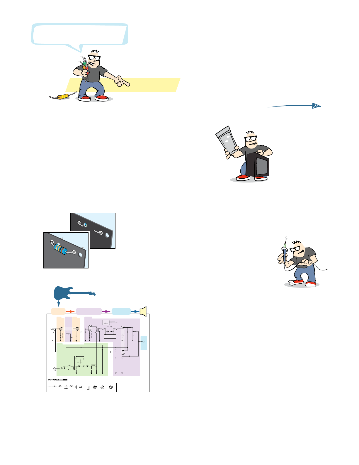
How to read resistor values ...................................... 7
Capacitor values .................................................. 7
Complete wiring diagram ........................................ 8
Prepping the cabinet ............................................. 9
Prepping the boards ............................................. 10
Installing the chassis-mounted components ................... 11
How to wrap and solder the eyelet board ....................... 17
Tips for great soldering ......................................... 17
Filter cap eyelet board ........................................... 18
Main eyelet board ............................................... 19
Soldering and installing the eyelet boards ...................... 23
Connecting the eyelet board to the chassis components ....... 24
Installing the heater wires ...................................... 27
Completed 6G15 wiring ......................................... 30
Final assembly ................................................... 31
Testing and troubleshooting .................................... 32
Learning more: secrets revealed in the schematic .............. 34
6G15 circuit schematic ........................................... 35
Tube replacement chart ......................................... 39
COPYRIGHT WARNING
This material is protected by copyright and has been created by and solely for the purposes of StewMac.
You may not sell, alter or further reproduce any part of this material, or distribute it to any other per-
son. Where provided to you in electronic format, you may only print from it for your own private use.
Failure to comply with the terms of this warning exposes you to legal action for copyright infringement.
How to build this kit!
stewmac.com © 2018 StewMac

stewmac.com 1 © 2018 StewMac
Reverb you can't
get from a pedal.
Be excited!
This is the unit that put the waves in surf music!
Looks like an amp, sounds like a beach party.
This tube-driven reverb tank relies on good ol’
physics for a perfect eect. Your guitar signal
travels along two large suspended springs to
produce the reverb that launched the iconic
surf sound.
This reverb unit is an ICON
The greats of surf rock used this king of spring to get their submerged,
tubluar tones. Controls for dwell, mix, and tone take you from dark,
atmospheric decay to bright and snappy splash.
StewMac ICON KITS bring classics that are no longer made, or are simply
unaordable, within reach. And the best part is you get to build them with
your own hands.
We give painstaking attention to parts selection, authentic materials, and
instantly recognizable details—everything that makes the originals so
sought after.
Build it with StewMac
These immersive instructions walk you through every step of creating this
tone machine. And you’ll learn a lot, gaining a deep knowledge of your
reverb unit’s inner workings.
Follow our steps closely for safety, too: we’ve carefully laid out a path that
even newcomers can follow in handling electrical components.
Building an electronics kit can seem daunting, but nobody makes it easier
than StewMac. Watch for helpful tips along the way, too—we’re here to help!
Let’s get building!
’64 REVERB UNIT KIT
ORIGINAL 6G15 CIRCUIT
stewmac.com 2 © 2018 StewMac
#10733 © 2018 StewMac
Processing
Gain Gain Processing
Power
Output
REVERB TANK
FOOTSWITCH
FUSE
INPUT
DWELL
IN OUT
V1
12AX7
V2
12AT7
V3
6V6 REVERB
TRANSFORMER
68319-A
POWER
TRANSFORMER
125A12A
+295V
+300V
+130V
+250V
+105V
1
2
+1.8V3
+160V
1
+250V
6
+120V
7
2
3
8
+2V+1.2V
1M.01μF
.0022μF
.047μF
.1μF
.01
.1μF
250pF
1.5K
1.5K
100K
100K
220K
1.5K10K
25μF 25V
1K2W
2.2M
10K
2W
22μF
500V
22μF
500V
22μF
500V
Totube heaters
and pilot light
25μF 25V
1500100K
2.2M
250μF 25V
250KL
TONE
50KL
MIXER
250KL
AC SWITCH
1 amp slow-blow
100Ω
100Ω
+120V
2
+285V
3
4
8
5
7
8
Here’s how to build this kit!
See page
17
Wiring comes later:
1. First, you’ll wrap the leads, connecting them without solder.
2. Then double-check all the connections. Don’t rush!
3. When everything checks out, it's time to solder.
The numbered steps tell you when.
Get the cabinet ready,
starting at Step
1
on page
9
.
You’ll prep the metal chassis
and the eyelet board too.
Learn more:
You don’t need to read the schematic, but it’s fun.
See how your guitar’s signal gets processed into sound.
This is on page 35.
Sort your components by type, using the parts list.
Quick look:
GroundJackTransformer Preamp tube
plate
grid
cathode
Power tube
grid
plate
cathode
screen
Capacitor ElectrolyticCap. Diode
Resistor Potentiometers Rectifier tube
plate cathode
filament
plate
Shielded
cable ’64 REVERB UNIT
6G15 CIRCUIT SCHEMATIC
OutputGain Processing
stewmac.com 3 © 2018 StewMac
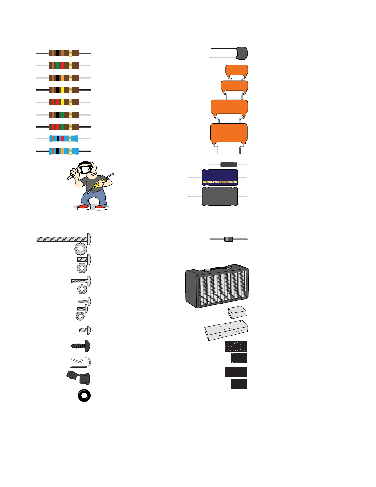
Parts list
Capacitors
r (1) 250pF 500V silver mica
r (1) .0022μF 600V Orange Drop
r (2) .01μF 600V Orange Drop
r (1) .047μF 600V Orange Drop
r (2) .1uF 600V Orange Drop
r (2) 25μF 50V electrolytic
r (3) 22μF 500V electrolytic
r (1) 250μF 25V bipolar electrolytic
222J 600V
+
25µF
103J 600V
473J 600V
104J 600V
Resistors
r (2) 100Ω .5W carbon composite
r (3) 1.5K .5W carbon composite
r (1) 10K .5W carbon composite
r (4) 100K .5W carbon composite
r (1) 220K .5W carbon composite
r (1) 1M .5W carbon composite
r (2) 2.2M .5W carbon composite
r (1) 1K 2W metal oxide
r (1) 10K 2W metal oxide
Brown Black Brown Gold
Brown Green Red Gold
Brown Black Orange Gold
Brown Black Yellow Gold
Red Red Yellow Gold
Brown Black Green Gold
Red Red Green Gold
Brown Black Red Gold
Brown Black Orange Gold
A magnifier helps!
Diode
r
(3) 1N4007 1000V rectifier diode
Cabinet and Chassis
r
(1) Cabinet
r
(1) Capacitor pan
r (1) Chassis
r (2) Eyelet boards
r (2) Insulator boards
250μF
22μF
250 5%
Hardware
r (2) 10-32 machine screw, 1-1/2"
r (2) 10-32 locknut
r (6) 8-32 machine screw, 3/8"
r (6) 8-32 locknut
r (3) 6-32 machine screw, 1/2"
r (3) 6-32 locknut
r (2) 4-40 machine screw, 3/8"
r (4) 4-40 machine screw, 1/4"
r (6) 4-40 locknut
r (4) Self-tapping screw
r (1) Black wood screw
r (1) Power cord clamp
r (1) Strain relief for power cord
r (6) Rubber grommet

stewmac.com 4 © 2018 StewMac
Transformers
r (1) Power transformer
r (1) Output transformer
r (1) Filter choke
Wire
r (1) White wire
r (1) Green wire
r (1) Blue wire
r (1) Red wire
Reverb tank & footswitch
r (1) Reverb tank
r (1) Footswitch
r (1) Reverb wiring kit
(shielded wire and 4 RCA plugs)
Tubes, lamps, fuses, and sockets
r (3) RCA-style jack
r (1) Two-lug jack
r (1) Three-lug jack
r (2) Nine-pin tube socket
r (2) Shield for nine-pin tube socket
r (1) Eight-pin tube socket
r (1) Tension clip for eight-pin tube socket
r (1) 12AX7 preamp tube (also called ECC83S)
r (1) 12AT7 preamp tube (also called ECC81)
r (1) 6V6S power tube
r (1) Fuse socket
r (1) Fuse (1 amp, slow blow)
r (1) Pilot lamp socket with lens
r (1) Pilot lamp bulb (#47)
Terminals, knobs, and cords
r (1) 100K control pot (L-linear taper)
r (2) 250K control pot (L-linear taper)
r (3) Knob
r (1) Three-lug terminal
r (1) Four-lug terminal
r (1) Power switch
r (1) Power cord
6
4
3
2
1
9
8
7
5
4
3
2
1
8
7
6
5
12AT712AX7 6V6
2
5
0
K
L
1
0
0
K
L
Parts list
Vintage-style push-back wire
lets you push the insulation
back instead of cutting it away.
BUT: Trimming the insulation
still works better.
stewmac.com 5 © 2018 StewMac
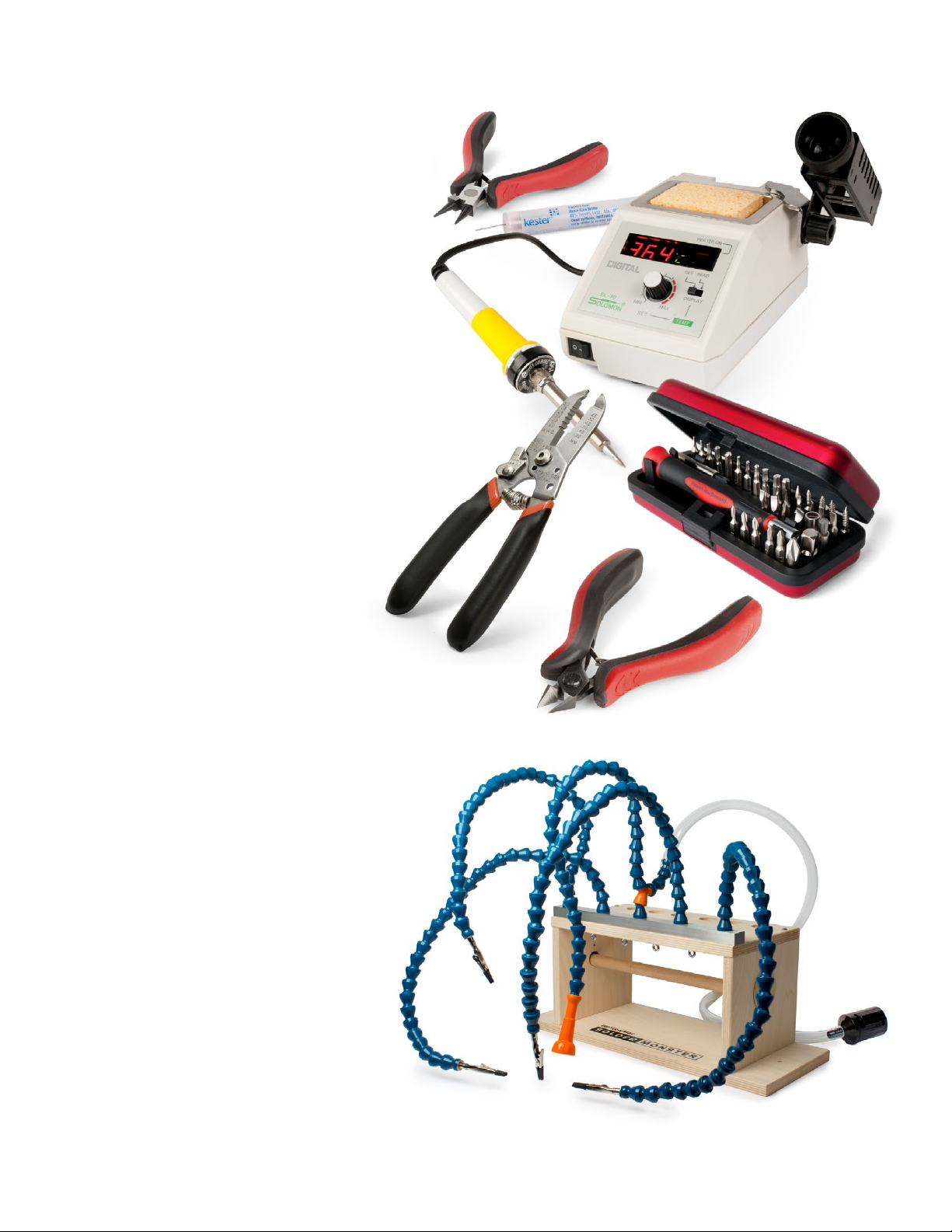
#0531
StewMac
Solder Monster
#3000
Guitar Tech
Screwdriver Set
#1606
Wire Stripper
#1607
Wire Cutter
#0501
Solomon SL-30
Soldering Station
#1609
Round Nose
Bending Pliers #0505
Kester
Pocket-Pak
Solder
Tools and supplies
Required Phillips screwdrivers, #1 and #2
Item #3000 Guitar Tech Screwdriver Set
Needle nose pliers
Item #1610 Long Nose Pliers
Wire cutter
Item #1607 Wire Cutter
Wire stripper
Item #1606 Wire Stripper
Soldering iron (preferably 40W)
Item #0501 Solomon SL-30 Soldering Station
Solder (at least one Pocket-Pak)
Item #0505 Kester Pocket-Pak Solder
Solder sucker
Item #0503 Solomon Solder Sucker
Drill with a 5/32" bit
5/32" for mounting eyelet board to chassis
Ruler
Item #4905 StewMac Shop Rule
Digital multimeter
Item #3618 Fieldpiece Pocket Multimeter
Snuer stick (bleed resistor)
Item #1552 Snuer Stick
Pencil
Wooden chopsticks
Glue
Wood glue, white glue, or contact
cement for gluing a paper label
inside the cabinet
Butane lighter or matches
For heating heat-shrink tubing
Helpful Round nose bending pliers
Item #1609 Round Nose Bending Pliers
Solder wick
Item #0504 Solder Wick, 5-foot roll
Soldering aids
Item #0521 StewMac Soldering Aids
Soldering stand
Item #0506 Solomon Soldering Stand
Printed circuit board vise
Chassis stand
Item #10750 Chassis Stand
Solder Monster, or helping hand tool
Item #0531 StewMac Solder Monster
Fine tip permanent marker
Scratch awl or center punch
Item #3000 Guitar Tech Screwdriver Set
Tray for loose parts
StewMac’s Solder Monster
holds parts while you solder

stewmac.com 6 © 2018 StewMac
How to use a snuffer stick
To discharge a capacitor, clip the snuer stick lead
to ground—preferably a mounting bolt on the
power transformer. Hold the tip of the stick to the
cap’s positive lead and use your multimeter to
watch the voltage drain to less than 18V.
High voltage, even when unplugged
When you turn on an amp, or in this case a reverb unit, the
capacitors are designed to take on a charge and hold it.
That stored voltage is enough to injure you seriously, or
even kill you.
These components aren’t a threat until the rst time you plug
the unit in. The stored electricity can be safely discharged to
ground with a snuer stick. See how to use it below.
Once your unit has been turned on, don’t touch the wiring
with your bare hands—even after turning the unit o. If
you need to press on a contact, use a chopstick or Sharpie
marker, which are both non-conductive. Don’t use a pencil,
because graphite is conductive.
It’s important that you understand the dangers so you’re
working safely. Here’s how to do it right.
Wear rubber-soled shoes
Rubber soles increase the insulation
between yourself and the ground.
Take off your ring
A metal ring on your finger can
bridge a hot connection to ground.
Wear safety glasses
Rosin-core solder sometimes bubbles up, and it can spew
molten specks into the air. You don’t want molten solder in
your eyes.
It’s better not to work alone
Electrical shocks can incapacitate you, and having someone
available to call 911 can be a lifesaver.
Take breaks and stop when you’re tired
Fatigue leads to mistakes, and no one can aord mistakes
when working with electricity.
Stay suspicious
Whether it’s the rst time you’ve been inside live electron-
ics or the 100th time, don’t become complacent. If you
discharge the caps and walk away for a few minutes, check
again for residual voltage when you return. Capacitors can
self-charge through a phenomenon known as dielectric
memory.
Check before powering up
It’s easy to forget that you a left a stray tool or wire in the
chassis. It’s also easy to forget to re-attach the speaker wire,
and that can fry an output transformer in seconds. Constant
vigilance is your friend when working on electronics.
Always unplug it
Unplug the unit whenever you don’t specically need it
plugged in. Some points are always hot when the unit’s
plugged in, even if the power switch is o. These points
include the lugs on the fuse socket, power switch, and
standby switch.
Amp voltages are seriously dangerous!
Professionals
who work on
amps take these
safety habits
very seriously

stewmac.com 7 © 2018 StewMac
A resistor’s value—the amount of resistance it creates—is
rated in ohms (Ω ). Larger ohm values mean more resistance.
For example, a 100Ω resistor creates ten times as much re-
sistance as a 10Ω resistor.
The resistors used in this unit are too small to have value
numbers printed on them. Instead, a system of colored
bands tells their values. The key to reading these bands is
provided below. However, an easier way to decode these
bands is to download one of the many smartphone apps
for this purpose.
One band will be the nearest to an end of the resistor. That
band tells the rst value. Combine it with the value of band
2 to get a two-digit number (68 in our example below).
Multiply that number by band 3 (68 x 1,000 = 68,000). Thou-
sands are represented by the letter K, so this resistor is 68K
(kilo-ohms, or KΩ).
If there is a fourth band, it will be either silver or gold. This
indicates the tolerance allowed during manufacturing. The
resistors used in this kit have a +/- 5% tolerance, represented
by a gold band 4.
A magnifying glass helps a lot. The bands on a 470Ω resistor
are yellow/violet/brown, and the bands on a 47K resistor are
yellow/violet/orange. They’re easily confused!
Can’t read the colors?
You can always use a multimeter to test a resistor’s value.
Set your meter to ohms and connect the test leads on each
side of the resistor.
Capacitor values are typically printed on the component.
The key values with caps are their capacitance and voltage.
Think of a capacitor as a container that can hold electricity.
Capacitance, measured in farads, refers to how much elec-
tricity this container can hold—its capacity. One farad (1F)
would be much too large for use here. Caps for this unit
are rated in millionths of a farad, called microfarads (μF), or
trillionths of a farad: picofarads (pF). The voltage spec for
a cap refers to how much DC voltage it can handle at any
given time.
A unique property of capacitors is that they don’t allow DC
current to ow past them, only AC current. This is important
in some parts of audio circuits, such as the path between
a preamp stage and a power amp stage. Here, a “coupling
capacitor” will block DC voltage, allowing only the AC guitar
signal to pass.
Filter caps
Capacitors also lter out 60Hz hum, or “ripple,” after the AC
current from the wall is converted to DC. These capacitors
are called lter caps, because they lter out the ripple from
a power supply. The lter caps in this unit are the 22μF
electrolytic capacitors.
Electrolytic caps
Electrolytic capacitors contain electrolyte: a liquid or gel
that gives them a large storage capacity. Electrolytic caps
are typically polarized.
Polarized caps
Some capacitors have polarity and some don’t. It’s extremely
important to install polarized caps correctly in a circuit. The
positive lead of an electrolytic cap will be indicated by an
indented ring around one edge of the capacitor. The nega-
tive lead will often be indicated by a band of arrows pointing
to the negative lead.
Installing capacitors with the polarity backwards will make
the circuit malfunction and quickly destroy the capacitor—
even causing it to explode.
Band 1 Band 2 Band 3 Band 4
1st Digit 2nd Digit Multiplier Tolerance
6 8 x1,000 +/- 5%
Blue
Read this band first (closest to an end)
Gray Orange Gold
BLACK 0 0 1 None +/- 20%
BROWN 1 1 10
RED 2 2 100
ORANGE 3 3 1,000
YELLOW 4 4 10,000
GREEN 5 5 100,000
BLUE 6 6 1,000,000
VIOLET 7 7
GRAY 8 8 0.01 +/- 10% SILVER
WHITE 9 9 0.1 +/- 5% GOLD
68K +/- 5%
K=1,000
NegativePositive
+
25μF
8μf
How to read resistor values Capacitor values

stewmac.com 8 © 2018 StewMac
POWER FUSE PILOT LIGHT DWELL INPUT MIX TONE OUTPUT
REVERB IN
FOOTSWITCH
REVERB OUT
V2
12AT7 V1
12AX7
V3
6V6
4
3
2
1
8
7
6
5
6
4
3
2
1
9
8
7
5
6
4
3
2
1
9
8
7
5
2
5
0
K
L
2
5
0
K
L
1
0
0
K
L
103J 600V
250 5%
14
11
10
M
17
23
31
9
8
7
6
5
13
22
29
35 36 37 38 39
30
4
21
33 34
3
20
27
16
2
12
15
19
25
1
M
18
24
26
32
28
+
25µF
103J 600V
222J 600V
+
25µF
104J 600V
104J 600V
473J 600V
250μF
Our diagrams
show a flat
view of the
metal chassis
Complete wiring diagram
Here’s the complete 6G15 wiring
When you’ve nished the kit, you’ll have connected all the
parts shown in this wiring diagram. If it looks complex now,
don’t worry; we’ll start at the very beginning and do this
one step at a time.
Your circuit-building skills will get stronger with each step!

stewmac.com 9 © 2018 StewMac
Prepare the cabinet for mounting the
chassis by first removing the back
panel.
STEP 1
Mount the power cord clamp
Drill a 5/64" pilot hole to mount the
power cord clamp. Locate the clamp
inside the left wall of
the cabinet, 1-1/2” from
the back panel ledge,
2” from the bottom.
Don’t drill through the cabinet! Use a
piece of masking tape on your drill bit
to mark the depth, or use a StewMac
Depth-stop Drill Bit (item #1712).
Use the black wood screw to mount
the cable clamp. You’ll secure the
power cord with this clamp later, after
the testing.
STEP 2
Glue the tube placement chart
Cut out the tube placement chart on
page 39. Put a thin coat of glue or
contact cement on the back and glue
it to the inside wall of the cabinet.
Also test to make sure you don’t have
continuity between the tip and the
shield of each plug, which would
indicate a short in the cable. If your
multimeter nds unwanted continu-
ity, the likely culprit is the inside (tip)
wire shorting to the outer shield. If
that happens, de-solder the tip con-
nection and redo that solder joint.
STEP 4
Mount the reverb tank
Remove the nuts from the four reverb
tank mounting screws and remove
your reverb tank from its box. Install
the reverb tank with the RCA jacks
facing up.
Reinstall the four reverb tank mount-
ing nuts, tightening each until they
are suciently tight.
Start by prepping the cabinet
Check off each
completed step
V?
12AX7
V?
12AX7
POWER FUSE PILOT LIGHT
V?
6V6
POWER TRANSFORMER
(Mounted outside)
OUTPUT TRANSFORMER
(Mounted outside)
4
3
2
1
8
7
6
5
6
4
3
2
1
9
8
7
5
6
4
3
2
1
9
8
7
5
1
M
A
1
M
A
1
M
A
14
11
10
M
17
23
31
9
8
7
6
5
5
22
29
35 36 37 38 39
30
4
21
33 34
3
20
27
16
2
12
15
19
25
1
M
18
24
26
32
28
’64 REVERB UNIT
ORIGINAL 6G15 CIRCUIT
StewMac®
ICON KITS
Use only 1-amp slow-blow fuse.
DANGER: Unplug the unit before changing tubes.
Tube locations from left to right:
6V6 12AT 7
(ECC81)
12AX7
(ECC83)
V3 V2 V1
#10733
Back
Here
STEP 3
Solder two reverb cables
Cut the shielded wire in the reverb
wiring kit to two 2' lengths. At the
ends of each piece, pull 3/4" of the
wire mesh shielding away to one side
and strip away 3/8" of the internal
cloth shielding. Insert the exposed
wire into an RCA plug so that it reach-
es the tip of the center post.
Solder this lead in place at the tip of
the plug. Don’t leave solder on the
outside of the plug tip, which would
keep it from tting into the jack. See
“Tips for great soldering” on page 17.
After the plug tip cools and the inside
solder joint is set, solder the braided
wire shielding onto the outside of the
plug. Solder the four plugs this way,
one on each end of the two cables.
These two cables will connect the
reverb tank to the chassis later on.
Test for continuity between the tips
of the plugs on each cable, then test
for continuity between the shields of
the plugs in the same way.
stewmac.com 10 © 2018 StewMac
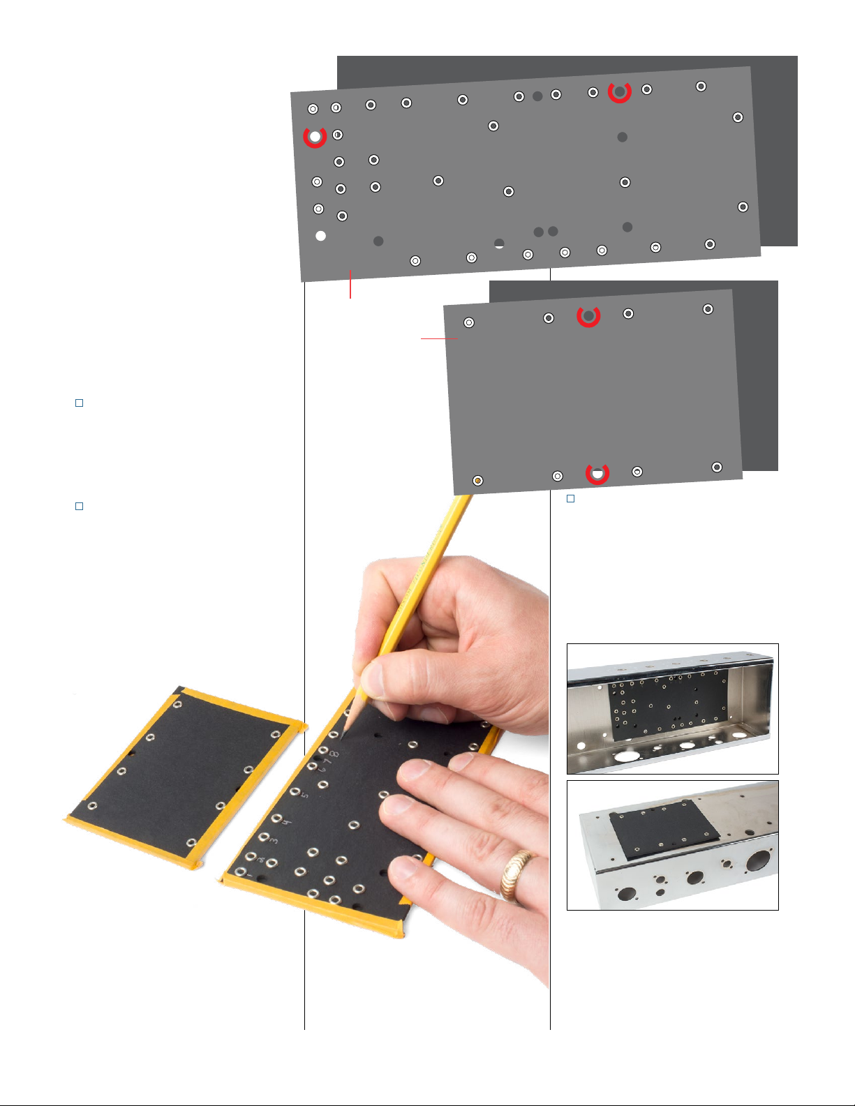
STEP 7
Number the eyelets and holes
These instructions will refer to the
eyelets and holes on the main eyelet
board by number and on the lter cap
board by letter. Use a pencil to mark
these numbers and letters onto the
boards as illustrated above.
The main board will be mounted
inside the chassis, and the lter cap
board will be mounted on the outside.
In the photo above, we’ve positioned
the empty boards just to show their
eventual mounting locations.
14
11
10
M
17
23
31
9
8
7
6
5
13
22
29
35 36 37 38 39
30
4
21
33 34
3
20
27
16
2
12
15
19
25
1
M
18
24
26
32
28
H
D
GM
M
C
F
B
E
A
Main board
Filter cap board
Insulator
Insulator
Prepping the eyelet boards
This circuit is built on two eyelet
boards. Signal processing happens on
the main board, and a smaller board
holds the lter capacitors.
For each eyelet board there’s a blank
board of the same size. These blanks
serve as insulators to keep the eyelet
board circuits from contacting the
metal chassis.
The pairs of boards mount to
the chassis with machine screws.
Mounting holes are already in the
eyelet boards, but you’ll need to
drill matching holes in the insulator
boards.
STEP 5
Tape the boards together
Noting the eyelet holes, align each
eyelet board with its insulator and
tape the paired boards together.
STEP 6
Drill the insulator boards
The mounting holes are pre-drilled
in the eyelet boards. Through them,
you can see the undrilled insulator
board taped behind. Using the holes
marked "M" on the drawing above as
a guide, drill through the insulator
boards with a 5/32" drill bit. Set the
insulator boards aside for later.
stewmac.com 11 © 2018 StewMac
POWER FUSE PILOT LIGHT DWELL INPUT MIX TONE OUTPUT
REVERB IN
FOOTSWITCH
REVERB OUT
V2
12AT7 V1
12AX7
V3
6V6
POWER TRANSFORMER
(Mounted outside)
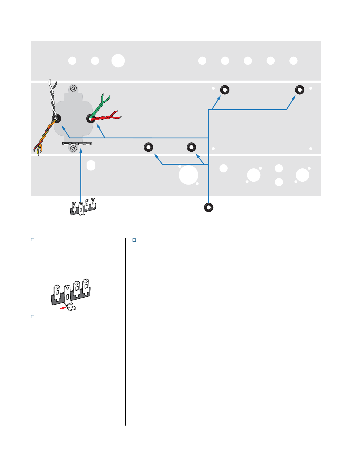
STEP 8
Install six rubber grommets
Squeeze these into the six holes for
strain relief for the wires that will pass
through the metal chassis.
STEP 9
Prep one terminal strip
With a wire cutter, snip the mounting
hole on the four-lug terminal strip as
pictured. You’ll mount this terminal
strip as part of the next step.
Installing the chassis-mounted components
STEP 10
Mount the power transformer
The power transformer has nine leads,
including two pairs with matching
colors, plus ve wires with dierent
colors. Twist the same-color pairs
together.
The other five wires allow you to
wire the unit for dierent voltages,
depending on the electrical system
where you live. The black wire is used
in all cases, and it’s twisted together
with another wire depending on your
country’s voltage:
100V: orange
120V: white
220V: black/yellow striped
240V: black/red striped
In North America for example, you
would twist the white wire together
with the black wire for 120V.
Twist the three unused transformer
wires together. You’ll terminate them
independently in a few steps. Pass the
red and green twisted pairs through
the grommeted hole under the fuse
socket. Pass the rest of the wires
through the grommeted hole closest
to the outside wall of the chassis.
Mount the transformer on the outside
of the chassis using 8-32 machine
screws. Secure the screws inside the
chassis with 8-32 locknuts. Mount the
four-lug terminal strip under the rear
locknut as shown.
Pull these wires tight once the power
transformer is mounted, but make
sure the grommets do not pull out of
their holes.
Snip

stewmac.com 12 © 2018 StewMac
STEP 11
Prep one grounding strip
With a wire cutter, snip the mounting
hole on the three-lug terminal strip as
pictured. Cut a 1" piece of green wire
and remove the insulation. Wrap and
solder the wire across the terminals,
electrically connecting all three lugs.
This will be used as a grounding strip.
STEP 12
Mount the output transformer
The output transformer has red, blue,
and yellow leads. Thread the red and
blue leads through one rubber grom-
met as shown, and the yellow lead
through the other grommet.
Using two 8-32 machine screws and
locknuts, mount the output trans-
former to the outside of the chassis.
STEP 13
Mount the filter choke
The lter choke has two black leads.
Twist these leads together and thread
them through the grommet with the
red and blue output transformer leads
as shown.
Using two 8-32 machine screws,
mount the lter choke to the outside
of the chassis. Mount the modied
three-lug grounding strip under the
front locknut.
STEP 14
Mount socket V3 + tension clip
Orient socket V3 so pin 1 is nearest the
opening of the chassis. Use two 4-40
x 3/8" machine screws to mount the
socket outside of the chassis. As you
install this socket, add the tension clip
to support the tube. This clip is held
by the same machine screws that
mount the socket.
STEP 15
Mount sockets V2 & V1
Use two 4-40 x 1/4" machine screws to
mount each nine-pin socket. Position
the sockets so pin 3 is on the side
toward the opening of the chassis.
STEP 16
Install the RCA jacks
Mount the three RCA jacks in their
respective holes. These jacks are for
the reverb in, reverb out, and the
footswitch.
Solder
Wrap
Snip
POWER FUSE PILOT LIGHT DWELL INPUT MIX TONE OUTPUT
REVERB IN
FOOTSWITCH
REVERB OUT
V2
12AT7 V1
12AX7
V3
6V6
FILTER CHOKE
(Mounted outside)
4
3
2
1
8
7
6
5
6
4
3
2
1
9
8
7
5
6
4
3
2
1
9
8
7
5
OUTPUT TRANSFORMER
(Mounted outside)

stewmac.com 13 © 2018 StewMac
STEP 17
Install the power switch
Mount the power switch with its two
lugs facing up for soldering later.
STEP 18
Install the fuse socket
Mount the fuse socket so its side lug
is facing up, toward the open side of
the chassis. This makes it easier to
solder later.
STEP 19
Install the pilot lamp socket
Mount the pilot lamp socket by screw-
ing the lens from the outside into the
socket assembly. Position the socket
so the tabs are facing up for soldering.
STEP 20
Connect two 100Ω resistors to
the lamp socket
Twist one lead from each of two 100Ω
resistors together to join them. Wrap
the other leads of these resistors to
the lugs of the pilot lamp socket.
Don’t solder the pilot lamp lugs yet,
but solder the twisted resistor leads
to each other and then solder the
twisted leads to the middle lug of
the three-lug terminal strip under the
pilot lamp assembly.
STEP 21
Install the control pots
Mount the pots so their lugs are facing
up. When we refer to these lugs as left
or right, it’s assuming you’re looking
at the pot from the same point of view
as the wiring diagram. Mount them
left to right, as follows:
Dwell: 250KL
Mix: 250KL
Tone: 100KL
POWER FUSE PILOT LIGHT DWELL INPUT MIX TONE OUTPUT
REVERB IN
FOOTSWITCH
REVERB OUT
V2
12AT7 V1
12AX7
V3
6V6
2
5
0
K
L
2
5
0
K
L
1
0
0
K
L
6
4
3
2
1
9
8
7
5
6
4
3
2
1
9
8
7
5
4
3
2
1
8
7
6
5

stewmac.com 14 © 2018 StewMac
STEP 22
Install two jacks
Mount the three-lug jack in the input
hole and the two-lug jack in the out-
put hole. Turn the jacks as pictured,
with the lugs of both jacks facing up.
Run the leads of a 1M resistor through
the right and left lugs of the input
jack, positioning it out of the way
of a guitar cable plug. It doesn’t
matter which direction the resistor is
attached, because resistors aren’t po-
larized. Wrap the lead going through
the left lug through the middle lug.
Solder the left lug and middle lug
connections, but not the right lug
connection yet.
STEP 23
Install one capacitor
Wrap and solder one lead of a .01μF
Orange Drop cap to the left lug of the
tone pot. Solder the other lead of this
cap to the back of the tone pot.
Always set pots to zero before sol-
dering to their housing. This way, if
the inside components do get a little
too hot it won't leave an imprint in a
position you might need to use later.
STEP 24
Install the silver mica capacitor
Wrap one lead of a 250pF silver mica
cap through the right lug of the mix
pot. Wrap the other lead of this cap
through the middle lug of the tone
pot. Solder both leads in place.
STEP 25
Add one jumper
Cut one 4-1/4" white wire.
Wrap one end through the right lug
of the output jack and wrap the other
end through the middle lug of the
mix pot. A connecting wire like this is
called a jumper.
Solder both ends of this jumper in
place.
STEP 26
Install power transformer leads
Run the white lead from the power
transformer to the side lug of the fuse
socket. Trim it to t and solder it. Trim
and solder the black lead to the left
lug on the power switch.
POWER FUSE PILOT LIGHT DWELL INPUT MIX TONE OUTPUT
REVERB IN
FOOTSWITCH
REVERB OUT
V2
12AT7 V1
12AX7
V3
6V6
2
5
0
K
L
1
0
0
K
L
6
4
3
2
1
9
8
7
5
6
4
3
2
1
9
8
7
5
4
3
2
1
8
7
6
5
103J 600V
250 5%

stewmac.com 15 © 2018 StewMac
STEP 27
Power transformer green leads
Run the two green wires from the
power transformer to the lugs on
the pilot lamp socket (either wire can
go to either lug). Trim these wires to
length and wrap them onto the lugs.
Don’t solder these connections yet.
Despite being green, these leads are
not ground wires. They supply power
to the pilot lamp, and after jumper
wires are connected later they will
also power the tube heater laments.
STEP 28
Power transformer red leads
Trim one of the power transformer’s
red leads to an appropriate length
and wrap one lead through one of
the lugs of the three-lug grounding
strip under the pilot lamp assembly.
You can twist the other red lead in
with itself to keep it out of the way.
This lead will be connected to the
eyelet board once the eyelet board
is installed.
STEP 29
Terminate the power
transformer’s unused leads
The three unused leads from the pow-
er transformer will carry hundreds
of volts, so they need to be safely
terminated and not hanging loose in
the chassis.
Cut these wires to length and solder
them to the three ungrounded lugs of
the four-lug terminal strip as shown.
These three lugs are not grounded or
connected to any components, which
makes them a safe place to anchor
these unused live wires. The remain-
ing lug on this strip is grounded to
the chassis, and will be used later to
ground the power cord.
POWER FUSE PILOT LIGHT DWELL INPUT MIX TONE OUTPUT
REVERB IN
FOOTSWITCH
REVERB OUT
V2
12AT7 V1
12AX7
V3
6V6
6
4
3
2
1
9
8
7
5
6
4
3
2
1
9
8
7
5
4
3
2
1
8
7
6
5

stewmac.com 16 © 2018 StewMac
STEP 30
Connect output transformer's
blue and yellow leads
Trim the blue wire from the output
transformer to an appropriate length
and solder it to pin 3 of socket V3.
Trim the yellow wire from the output
transformer to an appropriate length
and solder it to the center lug of the
reverb in jack.
Leave the red output transformer lead
free for now; you will install it to the
eyelet board later on.
STEP 31
Add two jumpers
Add a 2" white jumper between pin 2
of socket V1 and the center lug of the
footswitch jack. Solder this jumper in
to pin 2 of socket V1.
Add a 3/4" white jumper between the
center lug of the reverb out jack and
the center lug of the footswitch jack.
Solder the connection to the center
lug of the reverb out jack.
Solder the connection to the center
lug of the footswitch jack along with
the jumper from socket V1.
STEP 32
Inspect and double-check
This is a good time to step away from
the project for a few minutes and
take a break.
When you’re ready to go at it again,
carefully review every connection
you’ve made so far.
When everything checks out, you're
ready to move on to the eyelet board.
Be suspicious!
Assume there's a mistake and
you’re the one who’ll find it.
POWER FUSE PILOT LIGHT DWELL INPUT MIX TONE OUTPUT
REVERB IN
FOOTSWITCH
REVERB OUT
V2
12AT7 V1
12AX7
V3
6V6
4
3
2
1
8
7
6
5
6
4
3
2
1
9
8
7
5
6
4
3
2
1
9
8
7
5

stewmac.com 17 © 2018 StewMac
Wrap
Don’t solder the components as they
go onto the eyelet board. Instead
wrap all the parts onto the board,
bending their leads tightly so the
parts stay in place without solder.
Inspect
When all the parts are in place, stop
and inspect. Go back over every step.
Careful inspection is the best way to
make sure your unit works the rst
time you turn it on.
Solder
Solder each connection point only
once. Reheating to add another part
makes a messy, faulty solder joint.
Use the soldering tips below to get
professional results.
How to wrap and solder the eyelet board
nDon’t think of solder as glue. Good
mechanical connections make good
electrical connections. Solder’s job
is to nalize an already good joint,
not to hold the parts on the board.
So wrap the leads tightly for good
electrical contact before soldering.
nMelt a small amount of solder onto
the tip of the iron (“tinning" the iron).
Hold the tip against the joint for a few
seconds, until the connection reaches
soldering temperature.
Also tin component leads like multi-
strand wires to help the solder ow.
Tips for great soldering!
nKeep your soldering tip clean by
wiping it often on a damp sponge.
Keep it tinned by occasionally melting
a little solder onto it.
nFeed solder to the connection not
to the iron. Keep the iron on the con-
nection for a second longer to allow
time for all of the ux to cook out of
the joint.
nDon’t ever blow on the hot solder
or touch anything until the joint is
completely cool. A good solder joint
is shiny—a sign that it was left to cool
undisturbed.
nTrim away the excess wires after the
joint has cooled.
nPlan ahead so each joint is only
soldered once. Resoldered joints are
messy and more likely to fail.
nPosition the parts so their specs face
out so you can read them later. Many
builders also align resistor bands to
read in the same direction.
nHow much insulation to strip? With
plastic insulation, strip 3/8" from the
wire ends. Push-back wire works best
when you strip away about 1/4" of the
cloth wrap.
Put the lead through the eyelet Bend it tight against
the opposite side
Solder after
all the parts
are in place
Trim away
excess wire

stewmac.com 18 © 2018 StewMac
A
E
B
F
C
G
D
H
22μF
22μF
22μF
STEP 33
Add three capacitors
Use the small eyelet board for the
three filter capacitors. Note that
these caps are polarized and
must be installed in the correct
orientation.
Add a 22μF electrolytic capacitor
with the positive lead wrapped
through eyelet F and the negative
lead through eyelet B.
Add another 22μF electrolytic cap
with the positive lead through eyelet
G and the negative through eyelet C.
Wrap a third 22μF electrolytic cap
between eyelets H (positive lead) and
D (negative).
STEP 34
Add two jumpers
Wrap a 1-1/4" green jumper between
eyelets B and C.
Add another 1-1/2" green jumper
between eyelets C and D.
STEP 35
Add one resistor
Add a 10K resistor between eyelets
G and H.
STEP 36
Add three more jumpers
Add a 6" green jumper to eyelet B.
Add a 5-1/4" red jumper to eyelet F.
Add a 5-1/4" white jumper to eyelet G.
Set lter cap board aside for now, and
let’s get started on the main board!
Wrapping parts onto the filter cap board
Table of contents
Other StewMac Amplifier manuals


