HARNITEK Thermopod User manual

Table of Contents
1. Important information 2
2. Safety information 2
3. Introduction 4
4. Supplied Components 5
5. Thermopod Unit Specification 6
6. Thermopod Installation 8
7. Hydraulic Connections 10
8. Thermopod Panel Installation 14
9. Thermopod Testing 17
10. Electrical Connections 19
11. Machines On-line Operational Instruction 21
12. Controller Starting and Setting 23
13. System Commissioning 23
14. Tables of parameter and status 23
15. Inspection and Maintenance 24
16. Relocation after first Installation 24
17. Trouble Shooting 25
18. General Conditions of Guarantee 26
19. User Registration – Guarantee Card 27
Installation Manual
Thermopod
Solar Assisted Heat pump
Thermopod - Installation Manual 1 | Page

1 Important information
This manual is intended as a general guide and does not supersede local codes in any way. Consult authorities
having jurisdiction before installation. This appliance must only be installed by a qualified person who is certified and
trained to operate solar assisted heat pump system.
On receipt of Thermopod, all parts must be checked for damage before signing. Any damage related to
transportation is the responsibility of the purchaser’s shipping company and should be promptly addressed.
The Thermopod must be used only indoors in applications for which it was intended. Any misuse of this unit can
cause personal injury and/or damage to equipment.
Do not modify any electrical connections of the Thermopod solar assisted heat pump system without permission.
Otherwise, it will invalidate the guarantee. If the units are installed at place where the voltage is unstable, voltage
stabilizers are required. Further details please consult with local electrician.
Please note that HARNITEK, as the manufacturer, decline any responsibilities as regards damages deriving from an
incorrect installation and a failure to follow the instructions detailed in the document. Any damage or mal-function of
systems caused by non-conformance with this manual and/or any deviation from this manual will invalidate the
guarantee.
Marking
Thermopod is CE marked.
The CE marking means that HARNITEK ensures that the product meets all regulations that are placed on it based on
relevant EU directives. The CE mark is obligatory for most products sold in the EU, regardless where they are made.
Symbols
Caution
This symbol indicates important information about what you should pay attention to when install and/or maintain the
units.
Warning
This symbol indicates danger might occur on machine or person.
Note
This symbol indicates tips that help to facilitate the usage of the product.
Disposal
Leave the disposal of the packaging to the installer who installed the product or to special waste
stations.
Do not dispose of used products with normal household waste. It must be disposed of at a special
waste station or dealer who provides this type of service.
Improper disposal of the product by the user results in administrative penalties in accordance with
current legislation.
2 Safety information
Before install the unit, make sure you read all the “Safety precautions”.
Please report to your supply authority and obtain their consent before connecting this equipment to the power supply
system.
After installation, perform the test run to ensure normal operation. Then explain to the actual users for the “Safety
Precautions”. Use and maintain the units according to the detail steps on the Operation Manual provided by the
manufacturer.
Thermopod - Installation Manual 2 | Page

Both the Installation Manual and the Operation Manual must be given to and kept by the actual users.
Warning
The unit must be installed by the professional trained persons. Ask an installer or an authorized technician to
install the unit. If the unit is installed improperly, electric shock, or fire may be caused.
For installation work, follow the instructions in the Installation Manual; use tools and pipe components specified
in this manual that are made for special use with refrigerant in the outdoor unit.
The unit must be installed according to the instructions in order to minimize the risk of damages by
earthquakes, typhoons, or strong winds. Improperly installed unit may fall down and cause damages or injuries.
All electric work must be performed by a qualified technician according to local regulations and the instructions
given in this manual. The unit must be powered by dedicated power lines and the correct voltage and circuit
breakers must be used. Power lines with insufficient capacity or incorrect electrical work may result in electric
shock or fire.
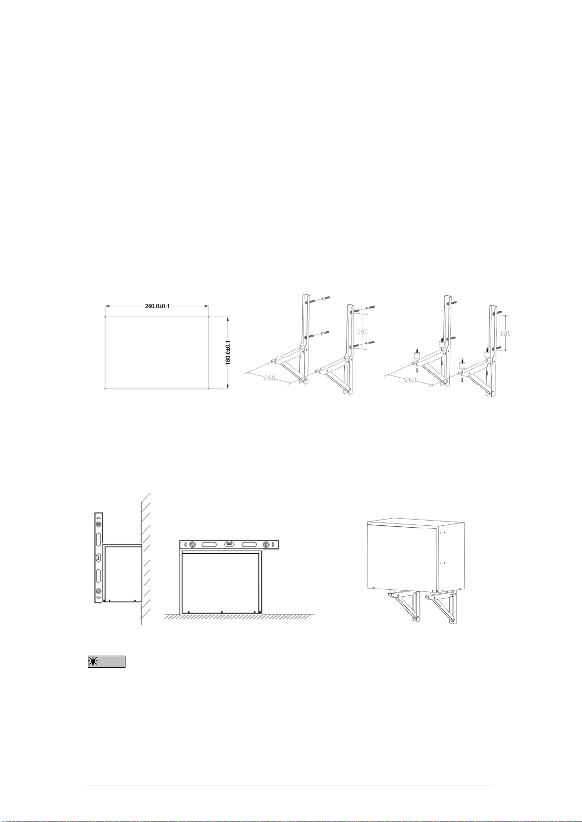
The unit must be securely installed on a structure that can sustain its weight. If the unit is mounted on an
unstable structure, it may fall down and cause damages or injuries.
The cover plate of the electric control box must be firmly fixed. If the cover plate is mounted improperly, dust and
moisture may enter the unit, and it may cause electric shock or fire.
Make sure to use accessories authorized by the manufacturer and ask an installer or an authorized technician to
install them. If accessories are installed improperly, it may cause electric shock, or fire.
Do not remodel the unit. Consult an installer for repairs. If replacement or repairs are not performed correctly, it
may cause electric shock or fire.
The user should never attempt to repair the unit or transfer it to another location. If the unit is installed
improperly, it may cause electric shock or fire. If need be, the unit needs to be repaired or moved by a qualified
installer or an authorized technician.
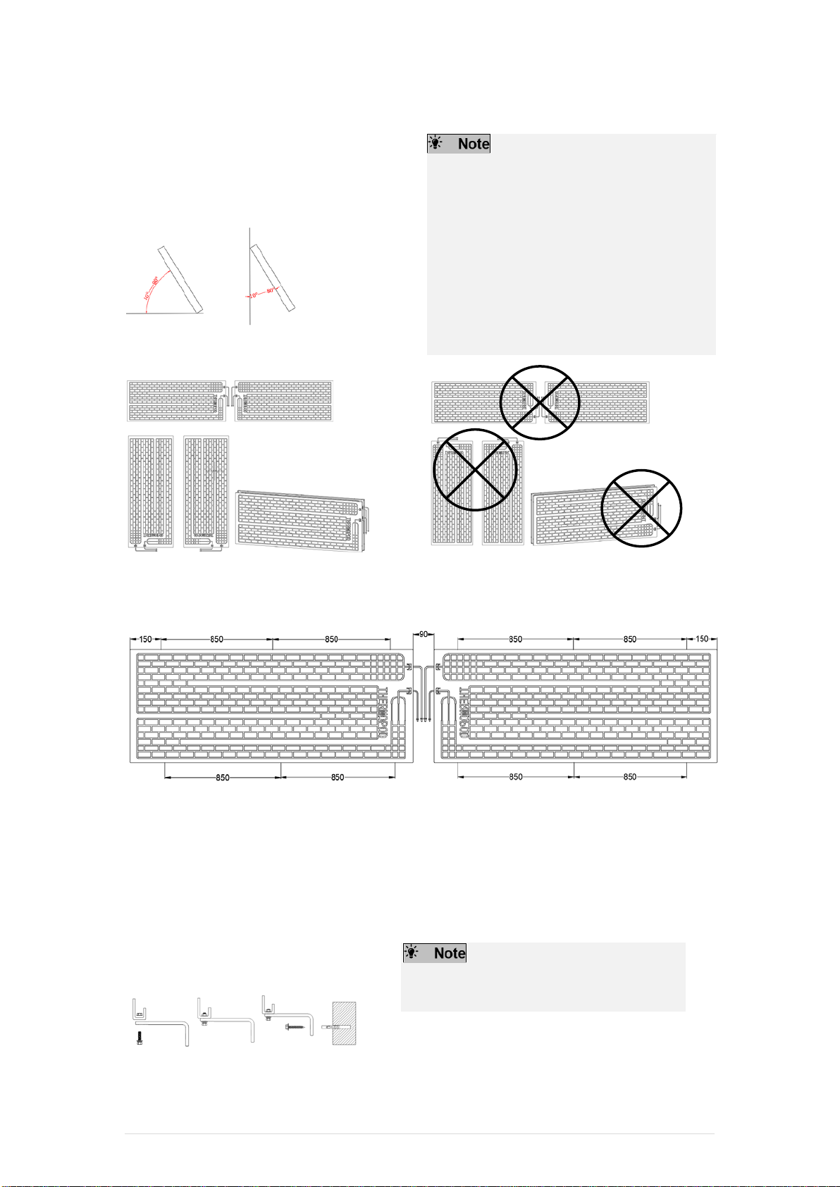
1.1 Before installation (Environment)
Caution
Do not install the Thermopod unit in outdoor location as it is designed for indoor use only. Otherwise electric
shock or breakdown may be caused by water drop, wind or dust.
Do not use the unit in an unusual environment. If the Thermopod unit is installed at place where it may be
exposed to steam, volatile oil (including machine oil), sulfuric gas, or briny air, the internal parts can be
damaged.
Do not install the unit where combustible gases may leak, be producted, flow, or accumulate. If combustible
gas accumulates around the unit, it may cause fire or explosion.
When installing the unit in a hospital or in a building where communications equipment are installed, you may
need to monitor the noise and electronic interference. Inverters, home appliances, high-frequency medical
equipment, and radio communications equipment can cause the Thermopod unit to malfunction or to
breakdown. At the same time, the noise and electric interference from the Thermopod unit may disturb the
proper operation of medical equipment, and communications equipment.
1.2 Before installation or relocation
Caution
Be fully careful when moving the units. Do not grasp it by the packaging straps. In order to avoid injuring your
hands by the parts, wear protective gloves while unpacking and moving it.
Be sure to safely dispose of the packaging materials. Packaging materials, such as nails and other
metal or wooden parts may cause injuries.
Do not wash the Thermopod unit. You may receive an electric shock.
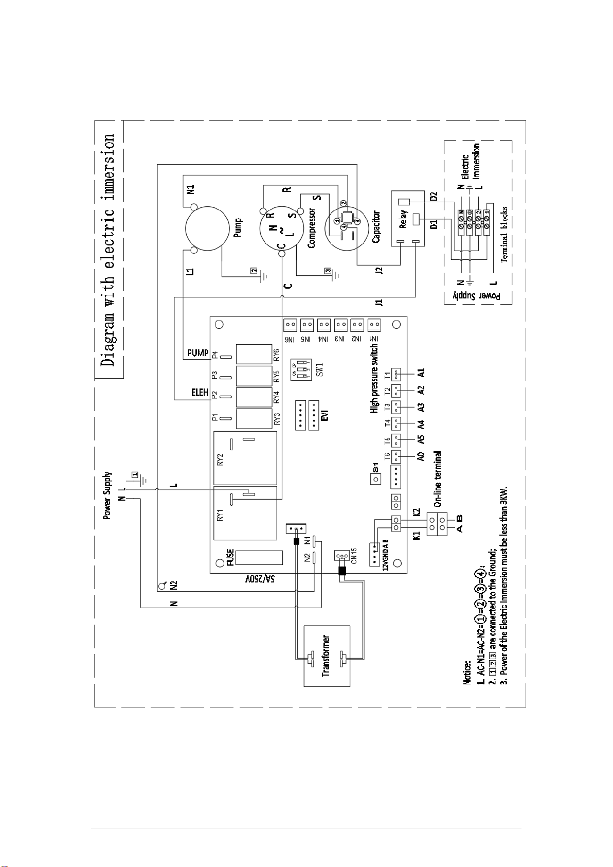
1.3 Before electric work
Caution
Be sure to install a circuit breaker. If it is not installed, there may be a risk to get an electric shock.
Please choose the standard cables with sufficient capacity as electric cable. Otherwise, it may cause a short
circuit, overheating, or fire.
When installing the electric cable, do not apply tension to the cables. Otherwise, the cables may be cut or
overheated resulting in a fire.
Thermopod - Installation Manual 3 | Page

Make sure you have ground wire for the unit. Do not connect the ground wire to gas or water pipes,
lightning rods, or telephone grounding lines. If the unit is not properly grounded, there may be a risk
to get an electric shock.
Make sure to use circuit breakers (ground fault interrupter, isolating switch (+B fuse), and molded
case circuit breaker) with the specified capacity (refer to the machine label). If the circuit breaker
capacity is larger than the specified capacity, breakdown or fire may result.
1.4 Before starting the test run
Caution
Before starting operation, check wheher all protective parts are correctly installed or not. Make sure not to get
injured by touching high voltage parts.
Do not touch any switch with wet hands. There may be a risk to get an electric shock.
When turning off the unit, make sure to wait at least 5 minutes before switching off the main power.
Otherwise, it may cause breakdown.
3 Introduction
Thermopod is a Solar Assisted Heat Pump System, it is designed to transmit thermal energy from the free natural
elements into water to achieve water heating for home use. The system can either be supplied with new cylinder or
be altered to work with user’s existing cylinders, turning the existing cylinder into a hot water storage tank.
The system is designed to heat the water in a standard 200 Litres cylinder up to 53°C all the time, and 60°C once a
week for anti-legionella. The unit is set to a default (can be adjusted) temperature as 53°C, when the temperature in
the cylinder drops by 5°C, the system will automatically switch on to heat the temperature back to the default
temperature.
In addition, there is an Energy saving mode, when switch this mode on, the system will automatically heat the water
to 3 different target temperatures at 3 different time. The 3 target temperatures and duration of time can be adjusted
according to users’ actual need.
Thermopod system gathers all advantages from common heat pumps. It will absorb energy from nature environment,
which is continuously renewable, by a very small consumption of electricity via a kind of medium, and generate
several times of thermal energy to heat the water.
Thermopod Components
Key Components
1. Thermopod Panels
2. Thermopod unit
3. Refrigeration Pipe
4. Standard Fitting
5. Water Fitting
6. Triangular Mounting Brackets
Thermopod - Installation Manual 4 | Page

4 Supplied Components
Packaging
Standard & Water Fittings kits are packed in the same box
with Thermopod panel.
Standard Fittings
Water Fittings - Accessories
L - Brackets x 12
Fused Spur 13A &
Socket Box x 1
3/4" M22*300mm
Flexible Hoses x 2
Hydraulic Seal x 2
Ball Valves x 2
Panel installation
Philips Self-tapping Screws x 12
Philips Hex Head Screws x 12
Light Duty Finned Anchors x 12
Flange Nuts x 12
Unit installation
Philips Self-tapping Screws x 4
Philips Hex Head Screws x 4
Light Duty Finned Anchors x 4
Anti-vibration mounts x 4
Brass Inline Y Filter x 1
3/4 Non-return Valve x 1
1/4” Inlet Line Connection x 1
3/8” Outlet Line Connection x 1
9.52mm * 250mm long thin
Pipe x 1
22mm/10mm * 65mm
Adapter x 1
Spares
Philips Self-tapping Screws x 2
Philips Hex Head Screws x 2
Light Duty Finned Anchors x 4
Flange Nuts x 2
Spares
Fuse 20A x 1
Fuse 5A x 1
Fuse 13A x 1
Screw x 4
3/4” 22mm Brass Fittings x 6
22mm Elbow x 1
22mm Equal Tee x 1
Note
The above mentioned water fittings are cutting ring fitting. If users need different kinds of water fittings or the water
pipe between Thermopod and the cylinder, please contact local sales person.
There are several ways for water connection. More details please consult local professional installer.
Always choose a solid and strong wall to install Thermopod units, otherwise, it may cause a risk of loosening or fall-
off.
Thermopod - Installation Manual 5 | Page

5 Thermopod unit Specifications
Thermopod
Solar Assisted Heat Pump
Casing:
Cold rolled steel
Chassis Base:
Galvanized steel
Water Pipe-work Connections:
3/4 inch
Compressor:
Sealed hermetically and covered with a layer of insulation to prevent heat loss and
absorb unnecessary vibrations
Refrigerant:
R134a- Tetra-fluoro-ethane, global warming potential (GWP) 1430
Condenser:
High performance steel shell & tube heat exchanger
Water Pump:
Dynamic conversion circulation pump
Compact design with low noise level, suitable for indoor installations
Performance
Unit
Rated Power Output
w
400
Max. Duel Panel Thermal
Performance Output
w
2690
Water Temperature
°C
53 (default setting, maximum temperature 60°C)
Dimensions and Weight
Casing
mm
1.2
Chassis Base
mm
1.5
Height
mm
395
Width
mm
500
Depth
mm
270
Weight
kg
39
IP Number
-
IP 21
Connections
Water inlet
inch
3/4
Water outlet
Inch
3/4
Refrigerant inlet
Inch
3/8
Refrigerant outlet
Inch
¼
Power supply
V / Hz
220 - 240 / 50
Specifications
Operating current (Max.)
A
5
Operating Temperature
°C
- 8 to +40
Refrigerant charge (R134a)
g
1400
Sound Level
dB(A)
Equal or less than 41
Max working pressure
Bar
(Water side) 8
*Figure as per EN16147:2017, EU812/2013, ISO9806:2013
Thermopod unit Dimensions
Dimensions
Thermopod - Installation Manual 6 | Page

Thermopod Panel Specifications
General
Finish:
Powder coated aluminium panel
Material Thickness:
2mm aluminium for increased mechanical strength
Protection:
Corrosion resistant and adaptability to all weathers
Fixing Orientation:
Can be installed in a landscape or portrait
Fixing Points:
Six fixing points per panel
Installation Angle:
Minimum of 10 degrees up to 80 degrees on vertical walls
** DO NOT LAY FLAT AS THIS WILL EFFECT THE FOLW OF R134a **
Dimensions and Weight
Unit
Height
mm
2000 (+-2mm)
Width
mm
800 (+-2mm)
Frame Depth
mm
25
Weight
kg
8.9
Thermopod - Installation Manual 7 | Page

6 Thermopod Installation
Selecting a proper location to install the Unit:
As the first step, an investigation on the target installation property will be necessary. It is important to locate a place
to install the Unit as close to the cylinder and the panels as possible.
Please refer to “How to Choose Installation Location for Thermopod” here after & “Guarantee Terms & Condition” in
item 16 in this manual.
For installation, the Thermopod units will come with the following parts:
Component
Qty
Thermopod
1
Rubber Gasket
4
Mounting Bracket
2
********Please install on a solid wall ********
How to Choose Installation Location for Thermopod
•Do not install the Thermopod in outdoor location as it is designed for indoor use only. (It is not waterproof.)
•Avoid locations where the unit is exposed to direct sunlight or other sources of heat.
•Select a location where has easy wiring access to the power souce.
•Avoid locations where combustible gases may be leak, produced, flowed, or accumulated.
•Avoid areas with corrosive gases and strong electromagnetic waves.
•Select a location that can bear the weight and vibration of the unit.
•Select a location where makes the water pipe between Thermopod and and water cylinder as short as
possible. The max pipe length is 5 meters. The longest Horizontal distance from Thermopod to cylinder is
3 metes; the longest vertical distance from Thermopod to cylinder is 2 meters.
•ALWAYS: Keep pipe to a minmum length. The shorter the pipe is the better the performance is.
The unit must be installed on horizontal position and on a solid wall if possible.
Horizontal Distance between Unit and Cylinder:
Vertical Distance between Unit and Cylinder:
Thermopod
Thermopod
Horizontal Distance
Max. 3 meters
Cylinder
Thermopod
Vertical Distance
Max. 2 meters
Cylinder
Cylinder
Thermopod - Installation Manual 8 | Page

Mounting the Unit
The Thermopod is wall-mounted by the brackets. The Thermopod can also be positioned on a suitable flat surface
where is close to the water cylinder.
Component
Qty
Thermopod
1
Anti-vibration mounts
4
Mounting Brackets
2
Tapping Screws
8
Light Duty Finned Anchors
4
Hex Head Screws
4
Installing brackets
1. Drill holes on the wall as illustrated.
2. Fit the brackets on the wall with the distance of 260mm by screws and anchors.
3. Install the triangular mounting brackets together by using the screws that the manufacturer supplied.
4. Fit Thermopod into place on the brackets by using the Anti-vibration mounts, screws and nuts that the
manufacturer supplied.
Installing on brackets
1. Install Thermopod on brackets.
2. Connect water and refrigerate pipes.
Note:
Check if the Thermopod was mounted in the applicable grooves on the brackets.
Ensure that the Thermopod is installed horizontally.
Note
The standard pipe-run distance between Thermopod and Thermopod panel is 10 meters.
The Thermopodshould be installed horizontally.
Make sure anti-vibration mount is in no deformation after installation.
Thermopod - Installation Manual 9 | Page

7 Hydraulic Connections
There might be impurities and / or substances in water which are harmful to the system. Check whether the quality of
the water being used is acceptable for home use or not. EU directive 98/83 EC shall be referred.
Meanwhile, there is a number of ways for hydraulic connections between Thermopod and cylinder.
Before Installation
Water In & Out Position
Water in and water out shall be found at the bottom of the Thermopod, which are used to be connected to the water
pipes.
Water Pipes for Connection
22mm Copper pipe shall be used for all water connections. All water
pipes connection between Thermopod and cylinder shall be insulated.
Good insulation will directly affect the performance of the system.
Cylinder
The insulation of cylinder will directly affect the performance of the
system. The user has to make sure the functionality of the cylinder.
It is recommended that the cylinder shall have a standing heat loss,
level at 1.4kw per day or 3 m2of surface area of the inside coil for heat
exchange or according to the local standard.
For Thermopod system, it is recommended that a cylinder with
maximum capacity of 200 litres shall be used. If capacity beyond 200
litres will directly affect the heating time and performance.
Insulation for All Water Pipe
Note – Insulation
In between Thermopod unit and water cylinder, all water pipes must be covered by the insulation material to reduce
heat loss. This directly affects the performance of system.
Water
In
Water
Out
Water
In
Water
Out
Water Pipe
Insulation
Material
Water Out – Flow
to Cylinder
Water In – Return
from Cylinder
Thermopod - Installation Manual 10 | Page

Unvented System Installation
Water from the top of cylinder
Water from the side of cylinder
Thermopod - Installation Manual 11 | Page

Water from the cylinder with internal coil
Vented System Installation
Water from the top of cylinder
Thermopod - Installation Manual 12 | Page

System Description
Description
Water inlet and outlet connections of the cylinder shall
be connected according to the vented and unvented
system diagrams.
The size of the hole of water inlet and outlet is 3/4".
To prevent unnecessary of heat loss, the length between
the point A (shown in the system diagram) and cylinder
in the connection shall be less than 25cm.
For the vented system, it is very important to keep
the bottom of water storage tank at least 1 meter
higher than both the top of Thermopod unit and
water cylinder.
For hydraulic connection between Thermopod and
cylinder, please ask your professional installer, who shall
install based on your actual situation.
Correct Position for Y-
filter Installation
Wrong Position for Y-
filter Installation
The Thermopod shall be positioned as close to
the water cylinder as possible so that to
minimize any forms of unnecessary energy
loss.
Keep bends and turns in the connections as
less as possible.
A chec
k valve shall be installed horizontally
between the water storage tank and the
cylinder, which is to ensure that the water
pressure is sufficient to open the valve;
otherwise air shall be drawn into the system.
Please seek advice from your water cylinder
installer.
Drain cock shall be installed at the lowest part
of the system for draining the system.
The inline Y-filter shall be installed
horizontally to defer any dirt, debris, or
impurities to flow into the condenser in
Thermopod, according to the diagram.This
directly affects the system’s functionality. The
guarantee will be invalid due to failure of
installation.
Multi-purpose Waterway Assembly
All components shall be bought and assembled from and
by your professional installers. It is not included in the
components of Thermopod.
Key Components of Multi-purpose Waterway
1. 22mm Elbow
2. 22mm/10mm * 65mm Adapter
3. 22 mm equal tee
4. 22mm diameter copper pipe
5. 22 mm equal tee
6. 52mm *240mm long thin pipe
7. Additional copper tube (required or not, based on
deep length of your cylinder)
Important Remark:
The Copper tube No.7 should be cut to a length to
reach 2/3rds down the cylinder length (1/3 from the
bottom).
1
2
6
7
5
34
2
3
6
Thermopod - Installation Manual 13 | Page

Temperature Probe Installation
THE TEMPERATURE PROBE MUST BE
INSTERTED INTO THE PROBE POCKET, OR DRY
POCKET OF THE CYLINDER.
The temperature probe is used to monitor the
temperature of the cylinder. The probe cable can
extend to the length of 10 meters.
If there is no pocket available to use, it shall be
attached 1/3rd position from the bottom of cylinder.
To ensure a reliable and solid contact between the
probe and cylinder side, thermal paste should be
used.
To make sure the reliable and solid contact
between the probe and cylinder side, the
thermal paste shall be used.
sensor pocket
sensor pocket
sensor pocket
sensor pocket
Steps
1. Locate the position of sensor pocket on the cylinder.
2. Remove the sensor pocket cover.
3. Pass the temperature probe through the cover.
4. Push the temperature probe as far as possible into the cylinder pocket, and then tighten the cover.
8 Thermopod Panel Installation
Position between Thermopod Panel and Thermopod unit
Choosing the Thermopod Panel location
•Select a location where the standard pipe-run
distance between Thermopodand Thermopod
panel is 10 meters, and minimum is not less than
5 meters. If the pipe-run height length is more
than 4 meters, please install “Return Bend” on
the pipe.
•ALWAYS: The shorter the pipe-
run distance,
the better the performance.
Standard pipe –run
distance: 10 meters,
Min. 5 meters
Height-length: more
than 4 meters with
“Return Bend”
Thermopod - Installation Manual 14 | Page

External Panel Installation
The location and the angle where the panels are
installed must be considered carefully.
On the ground or on the wall, the panels should be set at
an angle between 10°and 80°, preferably pointing south.
The panels should always be installed
downwards with the connections facing down
side. Two panels must install in the same style.
They must not have one landscape and another
portrait. The standard pipe-run distance
between Thermopod and Thermopod panels is
10 meters. The suggested space among two
panels on the connection’s side is 90mm.
Improper installation causes the system failure
which directly affects the performance and the
validity of guarantee.
Correct Installation
Wrong Installation
Thermopod Panel Positioning
Each panel must have 6 fixing points for
positioning, as below. The positioning of the panel
is ensured by L-brackets.
Method 1 - Vertical Wall Installing
To position the panel to a vertical exterior wall or
structure, better facing south, L-
brackets, nuts,
anchors and screws shall be used which can be
found in the box of Standard Fitting.
Method 2 - Roof Inclined Installing
The panel can also be installed on the inclined roof, facing
south.
There are more than one positioning solution, and shall be
discussed with the installer for alternatives.
The standard distance between Thermopod
and Thermopod panel is 10 meters.
Thermopod - Installation Manual 15 | Page

Panel Pipe Connection
A – Gas Line (Outlet) B – Liquid Line (Inlet)
Panels are supplied with stoppers in the pipe
connections. It is recommended to leave these in place
until the connection is made to avoid any dirt or dust
entering the opening.
There are two connections on each panel, Gas Line –
outlet and Liquid Line – inlet, which are linked with 1/4”
Inlet Line Connection and 3/8” Outlet Line Connection.
Step 1: Gas Line outlet A linked to 3/8” Outlet Line
connection
Step 2: Liquid Line inlet B linked to 1/4” Inlet Line
connection
When the caps in the connection of the
Thermopod panel are removed, there shall be
nitrogen from the holes. This is normal to have
“gas-out” sound as it means there is no leakage
or damage on the Thermopod panel during
transportation.
Removing the protective caps from the ends of
both line connections.
Tightening and twisting the nut in between Line
and connection by spanner according to the
values below,
Tube Diameter
(inches) Applied
Binary (Nm) Wrench
n°
1/4” 5 ~ 8 19
3/8” 12 ~ 15 21
Step 1
Step 2
Finished
A
B
1/4”
3/8”
Thermopod - Installation Manual 16 | Page

Refrigerant Pipe Connection
Gas Line and Liquid Line shall be found at the bottom of
the Thermopod.
In the package, there are two refrigeration pipes, 1/4"
and 3/8” refrigeration pipes, which are used for the
connections with 1/4" Inlet Line connection and 3/8”
Outlet Line Connection.
By using the refrigeration pipes, Thermopod and
Thermopod panel shall be connected.
Step 1: Identify and link the corresponding refrigeration
pipes to the corresponding line connections nearby
Thermopod panel.
Step 2: identify and link the corresponding refrigeration
pipes to the corresponding connections at the bottom of
the Thermopod.
Removing the protective caps from the ends of
both line connections.
Tightening and twisting the nut in between Line
and connection by spanner.
The length of two refrigeration pipes must be the
same.
The maximum pipe-run distance between
Thermopod and Thermopod panel is 15 meters,
while shall not be less than 5 meters.
All refrigeration pipe-run must be equal in
distance.
All refrigeration work shall be installed by an
accredited installer according to EN378. If the
installation is not conducted by an accredited
installer, the warranty will be invalid.
9 Thermopod Testing
Leakage test for Pipe Connection
Once all connections between Thermopod and Thermopod Panels have been done, the installer has to check for the
leakage.
Step 1: Cover all connections with the soap foam and see if there is any leakage.
Step 2: A load of nitrogen at a pressure of 10 bar shall be injected via pressure tap of 3-way valve.
Step 3: Hold and monitor the pressure change for 30 minutes, while check whether any of all connections has
leakage.
Gas Inlet
Liquid Outlet
Liquid
Outlet
Gas
Inlet
Liquid
Outlet
Gas
Inlet
Thermopod - Installation Manual 17 | Page

Step 4: If there is any pressure drop in 30 minutes, or if any leakage is found, identify and fix the leakage. Then
conducts the full leak test again until there is no leakage and pressure remains constant in 30 minutes.
Note
The pressure for the leak test must not be over 10bar in both Thermopod panel and pipe connection.
Caution
Warranty requirement that the Nitrogen pressure test and vacuum processing test must be evidenced with a picture,
to show the pressure level injected or the vacuum level respectively.
Vacuum Processing
This is a critical process for the system to be completely vacuum before loading the refrigerant fluid. The purpose of
this process is to remove all the air and moisture inside the pipe work and Thermopod panel. If the system is not
completely vacuum, the system will be soon deteriorated.
Step 1: Start vacuum process by using a vacuum pump.
Step 2: Hold the system in vacuum for at least 30 minutes or less than 20pa shown by vacuum manometer.
Step 3: Make sure no change in the vacuum manometer for 15 minutes after stopping the vacuum pump.
Step 4: After the vacuum process, the two valves shall be opened for the refrigerant to circulate.
Note
If the system deterioration caused by a failure of this vacuum process, it is not included in the warranty period.
Thread sealant is recommended for all existing thread connections.
Caution
For vented system, please adjust the water pump mode from default I / S1 to III / S3. This action can enhance the
internal pressure to draw air inside the water pipe.
Standard for vacuum completion: After 10 minutes of system operation, No Unusual Sound from Compressor, and
difference of two temperatures on the screen not more than 5 degrees.
Additional Refrigerant Charge
The Thermopod is pre-charged with 1400g of refrigerant R134a, sufficient enough for up to 10M of physical
separation pipe length between Thermopod and Thermopod panel.
The pipe-run length can be extended up to 15 meters of physical separation between Thermopod and Thermopod
panel. 20g of refrigerant R134a shall be added for every extra 1 meter length of pipe.
It is important for connections between
Thermopod and Thermopod panel to have as
less bends as possible, in which the load loss
shall be minimized. Check the additional
refrigerant charge accordingly.
Distance (M)
Addition Charge (g)
5 – 10
No additional charge
11
20
12
40
13
60
14
80
Max 15
Max 100
Thermopod - Installation Manual 18 | Page

10 Electrical Connections
Important Notes
Check the following conditions before implementing the electrical connections,
a) The system must only be electrically powered up after all completion of refrigerant connections, hydraulic
connections, and full system tests.
b) The water cylinder shall be completely filled and purged.
c) The system requires single phase, 220 - 240V / 50Hz power supply with earth connection. This should be
separately isolated and protected by an appropriate sized fuse. (Max. 13Amps)
d) The system is supplied with an appropriate fused spur.
e) The system has a connector and terminal airs which allows the connection of a back-up immersion heater. The
maximum rating is 3kW.
f) All electrical sockets connected to the system must be grounded.
g) Connections should always comply with the installation regulations according to the local electrical code and
legislation.
Electrical Immersion
Important Notes
For the diagram with electrical immersion, here
below is the connection part.
1. Second Power Supply
2. Immersion
3. Immersion L line
4. Ground
5. Immersion N line
6. Power N line
7. Ground
8. Power L line
Thermopod - Installation Manual 19 | Page

Thermopod Circuit Schematic Diagram
Diagram with electric immersion
Thermopod - Installation Manual 20 | Page
Table of contents
Popular Heat Pump manuals by other brands

York
York YLCA 50 user manual

Daikin
Daikin RXTQ-TAVJ9A manual

Daikin
Daikin MHC Installation & maintenance data

Carrier
Carrier 38CQ Installation, Start-Up and Service Instructions

Nibe
Nibe F730 user manual

American Dream Ultra Performance Geothermal
American Dream Ultra Performance Geothermal Copper Series Installation and service manual

Danfoss
Danfoss Optyma Plus INVERTER Series instructions

ICP
ICP PHJ3 Owner's information manual

Mitsubishi Electric
Mitsubishi Electric PUHZ-W85VHA2 Service manual

Bard
Bard Q24H1D installation instructions

Ariston
Ariston NIMBUS PLUS S NET manual

Beretta
Beretta Tivano Series Installation and operation manual