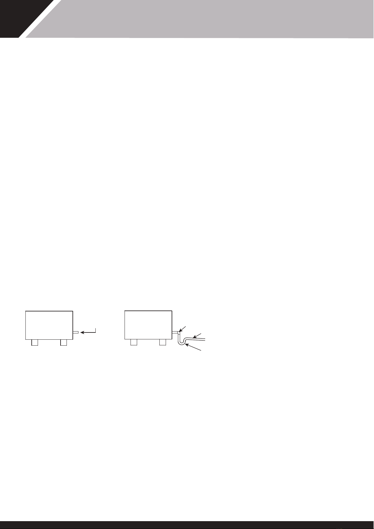
Dantherm calorex WA 634ACL Quick start guide

Page 1 SD331852 issue 5
Air/water heat pumps
Chillers and heater chillers
Owner installation manual (SD331852 issue 7)

2 SD331852 ISSUE 7
OWNER INSTALLATION MANUAL 634ACH/ACL/AHC /1222AC/1234BC/BHC /1834BHC /PP22BC

CONTENTS
HEATH AND SAFETY WARNING ..............................................4
AIR/WATER HEAT PUMPS.........................................................5
NOTE THAT WHEN A HEAT PUMP IS CHILLING
THE CYCLE IS REVERSED.........................................................6
THE HEAT PUMP CYCLE............................................................6
INSTALLATION ............................................................................7
1 SITING.......................................................................................7
2 AIR FLOW.................................................................................8
3. PLUMBING ..............................................................................9
4. DETERMINING WATER FLOW............................................ 11
5. WATER SCHEMATICS.......................................................... 14
ELECTROLYTIC CORROSION IN SWIMMING POOLS......... 16
ELECTRICAL (MACHINE WIRING AND SUPPLY) ................ 17
CHANGING THE POSITION OF THE DIGITAL
THERMOSTAT ON A PP22BC CHILLER ................................ 21
POOL PUMP SYNCHRONISING A POOL PUMP
WITH A PP22BC CHILLER...................................................... 25
ELECTRICAL CIRCUIT DIAGRAMS........................................ 26
CONTROLS AND INDICATION LAMPS ................................ 34
HEAT PUMP MALFUNCTION ................................................. 36
DATASHEETS............................................................................ 39
INSTALLATION DRAWINGS.................................................... 41
WINTERISING PROCEDURE................................................... 47
START UP PROCEDURE AFTER WINTERISATION .............. 47
WARRANTY CONDITIONS...................................................... 48
MACHINE RECORD LOG......................................................... 49
HEALTH AND SAFETY WARNING
As e dehumidifier embodies electrical and rotational equipment, ONLY competent persons
should carry out any work on is type of machine.
(SEE GUARANTEE)
3
SD331852 ISSUE 7

HEALTH AND SAFETY WARNING
This appliance can be used by children from eight years and above and persons wi reduced
physical, sensory or mental capabilities or lack of experience and knowledge if ey have been
given supervision or instruction concerning e use of e appliance in a safe way and understand
e hazards involved. Children should not play wi e appliance. Cleaning and maintenance shall
not be made by children wiout supervision.
Disconnect from e mains supply and wait ree minutes before removing panels and
commencing work on is machine.
HEATH AND SAFETY WARNING
4 SD331852 ISSUE 7
OWNER INSTALLATION MANUAL 634ACH/ACL/AHC /1222AC/1234BC/BHC /1834BHC /PP22BC

AIR/WATER HEAT PUMPS
MODELS COVERED IN THIS MANUAL
HC HEAT PUMPS
These heat pumps are heater chillers, designed for areas of e world where
e ambient temperature can vary from 7ºC to 50°C. The pool water is
heated when e ambient temperature is low and cooled when e ambient
temperature is high, enabling e user to enjoy e pool roughout e year.
The units are designed for swimming pools, using R134a as a refrigerant and
are ideally suited for operation in a tough climate.
CL, CH AND C HEAT PUMPS
These heat pumps are chillers and are designed to chill eier pools or domestic
water. These chillers are capable of operating in various conditions and come in
ree different types. The limits of operation are stated below:
WA634ACH and WA1234BC chillers operate in ambiant air temperatures
between 10ºC and 50ºC.
WA634ACL chillers operate in ambient air temperatures between 10ºC and
35ºC.
WA1222AC chillers operate is ambient air temperatures between10ºC and
40ºC.
WA 1834 chillers operate is ambient air temperatures between10ºC and 50ºC.
PP22BC chillers operate in ambient air temperatures between 10ºC and 50ºC.
All units have integral safety devices to protect e heat pump from internal
and external faults. Indicator lamps indicate operating mode. An adjustable
ermostat controls water temperature. Also a 6 minute cycle time delay is
incorporated.
5
SD331852 ISSUE 7

COOL GAS
HOT GAS
HEAT
EXCHANGER
EVAPORATOR
COLD LIQUID
REFRIGERANT
HIGH PRESSURE SIDE
CONDENSED
REFRIGERANT
AMBIENT
AIR
LOW PRESSURE SIDE
WATER OUT
WATER IN
1
2
3
4
COMPRESSOR
EXPANSION
VALVE
THE HEAT PUMP CYCLE
The CALOREX Swimming Pool Heat Pumps provides ermodynamic heating
by means of a vapour compression cycle, (similar to at employed in a
conventional refrigerator), in addition to operating as an active solar collector.
2The COMPRESSOR where it is compressed and upgraded
to a much higher temperature. The hot vapour now enters -
1The EVAPORATOR collects e heat from e outside ambient air,
pre-heated by e sun. In e Calorex swimming pool heat pumps, high
volumes of outside air are drawn into e unit by e fan and expelled
rough e evaporator fins. The evaporator has liquid refrigerant passing
rough it which is at a considerably lower temperature an e ambient
air. Therefore e air gives up its heat to e refrigerant which en
vaporizes. This pre-heated vapour now travels to -
3The CONDENSER where it is surrounded by e pool water.
e heat is given up to e cooler pool water and e now cold
refrigerant returns to its former liquid state but still under high
pressure from e compressor.
This pressure is released by passing e liquid rough -
4The EXPANSION DEVICE and from ere, now at normal
pressure, it is returned to e evaporator and e cycle starts
again.
COEFFICIENT OF PERFORMANCE
The eciency of a Heat Pump is usually called its ‘Coecient of Performance’
- (C.O.P.) which is simply a ratio of heat output to energy input, bo being
expressed in kW. Thus a Heat Pump absorbing 1 kW of electricity, collecting 4
kW of energy from e air, and delivering 5 kW of heat to e pool water is said
to have a C.O.P. of 5:1.
Naturally is ratio will vary according to e temperature of e ambient air.
NOTE THAT WHEN A HEAT PUMP IS CHILLING THE CYCLE IS REVERSED
6 SD331852 ISSUE 7
OWNER INSTALLATION MANUAL 634ACH/ACL/AHC /1222AC/1234BC/BHC /1834BHC /PP22BC

INSTALLATION
1 SITING
1. Ensure heat pump on site is as ordered, i.e. model, electrical supply and
factory fitted options.
2. Inspect unit for damage, in particular inspect e evaporator (finned side)
to ensure at it is undamaged. (Minor indentations in e fins do not affect
performance). If severely damaged, endorse delivery note in presence of
driver and send a recorded delivery letter to e transport company giving
details.
3. Provide a firm level base capable of supporting operational weight of unit;
spread load on timber floor.
4. Ensure water cannot collect under unit - recommend units are installed
on plins 100mm above finished floor level and to also aid condensate
drainage.
5. Allow adequate clearance to service panels on unit; recommend 500mm
minimum (see installation drawings).
6. All Calorex heat pumps are by design as quiet as is practical, however due
consideration should be given to siting in order to fully exploit is feature,
i.e. orientate inlet/outlet parallel to occupied premises.
7. Ensure loose debris such as leaves, grass cuttings, etc will not block air inlet
grilles.
8. Consider protection from extreme weaer conditions if installed externally,
i.e. lean-to-cover or building.
7
SD331852 ISSUE 7

TABLE 1
MODEL MINIMUM FREE AREA m2
INLET DISCHARGE
634 0.28 0.06
834 0.46 0.07
1234 0.39 0.12
1834 0.39 0.12
PP22 0.32 0.17
WRONG RIGHT
TYPICAL OUTSIDE INSTALLATION
FIGURE 1
WALL, FENCE OR HEDGE
TYPICAL INSIDE OR PLANTROOM INSTALLATION
FIGURE 2
WRONG RIGHT
Grill or apertures MUST comply wi figures (see Table 1)
SPACE COOLING/HEATING INSTALLATIONS
MINIMUM DISTANCE
TO BE 3m
MINIMUM DISTANCE
TO BE 500mm
HEAT
PUMP
IDEAL
POSITION
ALTERNATIVE POSITION COLD
WARM
IDEAL
POSITION
2 AIR FLOW
Due consideration must be given to air flow, i.e. do not obstruct inlet or
outlet and ensure discharge air cannot re-circulate to inlet. (See figures 1
and 2).
Required Free Areas to provide air flow to and from heat pumps when
installed in an enclosed area or where required to pass air rough a
wall, etc.
Free area is e available area rough which air can pass rough a grille or
louvres.
Note: If multiple units are installed in an enclosed area en e inlet free areas
required for each unit can be added togeer to form one inlet aperture.
BUT discharge from each unit must be kept separate and must not be
incorporated into one common duct system.
Note: ON AW1834BHC ducting must not be fitted directly to e unit. Inlet
duct spigots are available to order.
8 SD331852 ISSUE 7
OWNER INSTALLATION MANUAL 634ACH/ACL/AHC /1222AC/1234BC/BHC /1834BHC /PP22BC

INCORRECT DRAINAGE
FOR CONDENSATE
CORRECT DRAINAGE
FOR CONDENSATE
THIS TYPE OF
INSTALLATION SHOULD
BE AVOIDED ELBOW
ADEQUATE FALL
U TRAP
a. Calorex ‘34’ range Heat Pumps have water inlet/outlet connections as
follows:
634/1234 models ¾ “ BSP parallel, male.(wi ¾” BSPF x 1½” ABS male
adaptors supplied loose).
1834 models 1½” BSP parallel, male.
PP22BC ¾” BSP parallel, male or 50mm
The machine is supplied wi bungs fitted in e water connection fittings.
These need to be removed before e unit is installed.
b. The Calorex Pool Heat Pump must be connected in bypass aer e filter in
e return pipe to e pool. If an existing heater is being retained, en e
Calorex Heat Pump should be connected between e filter and e oer
heater.
c. Suitable breakable couplings should be installed local to heat pump.
d. If heat pump installed at lower level an pool water en isolation valves
should be fitted.
e. Drain valve or plug should be fitted to lower pipe to facilitate drain down in
winter period.
f. Connections on all models are by parallel female fittings sealed by silicone
mastic ese should be hand tightened only, oerwise damage may result
to e reads of plastic fittings.
g. The condensate drain at e base of e unit collects e condensation
from e evaporator fins. On 634/1234 and PP22 is should be run away
to waste via ¾” domestic waste piping using connector supplied. On
1834 models e waste piping needs to be 1½”. It is erefore necessary
to ensure at e Calorex unit is placed on a level plin so at e
condensate water can run away wi adequate fall to waste ie. ½” per foot
min and must incorporate a ‘u’ trap as to not overflow e edges of e
drip-tray inside e machine.
h. When e pipework installation is complete e pool pump should be
switched on and e system tested for leaks. Also check e filter gauge to
see at ere is not an excessive increase in back pressure. If everying is
en working normally e water circulating system is ready to use.
i. Water circuit to and from unit to be capable of maintaining wiin specified
limits e rate of flow required by heat pump (see data sheet).
j. All pipework must be adequately supported wi allowance for expansion/
contraction especially wi plastic pipework.
k. It is recommended at when installing water systems e last connections
to be made in e system should be e breakable connections to avoid
any stresses on to e unit connections.
3. PLUMBING
9
SD331852 ISSUE 7

pH 7.2-7.8
Total Alkalinity 80-120ppm as CaCO3
Total Hardness 80-250ppm as CaCO3
Total dissolved solids 1000ppm
Saline Water Except PPT22 8000ppm
Chlorine - free Cl Range 1.0-2.0ppm Domestic
Chlorine - free Cl Range 3.0-6.0ppm Commercial
Ozone 0.9ppm Max
Bromine 2-5ppm
Baquacil 25-50ppm
Aquamatic Ionic Purifier Max 2ppm Copper
IMPORTANT
1. Maximum pressure of water in heat pump circuit should not exceed 3.5kg/
cm2(50 psi)
FOR POOL APPLICATIONS THE FOLLOWING ALSO APPLY
2. All Pool Purifying Devices and Chemical Injection Systems to be fitted
down stream of heat pump unless installation is as per Filter dosing. This
includes e practice of dosing chemicals direct into Skimmer Basket, which
results in concentrated corrosive liquids passing over metal components.
3. Water quality must be maintained as follows
10 SD331852 ISSUE 7
OWNER INSTALLATION MANUAL 634ACH/ACL/AHC /1222AC/1234BC/BHC /1834BHC /PP22BC

33 LITRES PER MINUTE
MACHINE SIDE, MODEL AW634/1234
33 l/ m
WINDOW
POOL
WATER OUT
MACHINE SIDE, MODEL WA634/WA1234
33 l/ m
POOL
WATER IN
POOL
WATER OUT
POOL
WATER IN
33 LITRES PER MINUTE
WINDOW
4. DETERMINING WATER FLOW
PLUMBING.
Machine must be plumbed in bypass, see diagrams below (Label on side of
machine).
Adjust gate valve to give required flow rate as indicated rough window on
side of machine.
MODELS 634/1234
11
SD331852 ISSUE 7

DETERMINING WATER FLOW AW1834BHC
FLOW METER METHOD (SEE FIG 3).
Ensure isolation valves ‘A’ and ‘B’ and bypass valve ‘C’ are fully open. Slowly
close down bypass valve ‘C’ until correct flow rate is shown on e flow meter.
(See data sheets on pages 39 and 40) Remove handle and lock off valve ‘C’.
DIFFERENTIAL PRESSURE METHOD (SEE FIG 3).
By simply installing two filter pressure indicating gauges, one each on e
inlet and outlet of e heat pump, and a locking type gate bypass valve
in e bypass line, e flow rate rough e heat pump can be accurately
determined by e difference in e readings of e gauges.This pressure drop is
proportional to flow.
Flow rate should be set at e maximum differential.
Setting up e differential.
When e installation is complete, e procedure for setting e flow rate
rough e heat pump using two gauges is as follows:
1. Wi e heat pump switched off, ensure isolation valves ‘A’, ‘B’ and
bypass valve ‘C’ are fully open.
2. Switch on water circulating pump.
3. Note e water System Pressure on bo gauges - ey should read e
same, but because of manufacturing tolerances ey may have different
readings.
For example; wi a water system pressure of 5mhd e gauge on e inlet
may read 5 and e outlet gauge 5·5 erefore ere is a STATIC ERROR
DIFFERENCE of 0·5mhd.
4. Gradually close e bypass valve ‘C’ until ere is a difference in pressure
between e two gauges at is equal to e required pressure drop (see
data sheet) observing any static error on e gauges before beginning is
process.
5. Lock e bypass valve, or render it tamper proof, when correct setting is
achieved.
6. See data sheets on pages 39 and 40 for correct water pressure drop.
12 SD331852 ISSUE 7
OWNER INSTALLATION MANUAL 634ACH/ACL/AHC /1222AC/1234BC/BHC /1834BHC /PP22BC

WATER
IN
WATER
OUT
AIR INLET
THERMOSTAT
REMOVE BUNGS
BEFORE INSTALLING
HEAT PUMP
PP22BC FLOW RATE 1980L/HOUR
DETERMINING THE WATER FLOW PP22BC
The heat pump is fitted wi a water flow switch which inhibits e operation of
e heat pump when e water flow is less an e figure shown in e table
below.
Adjust e flow rate until e flow rate is adequate. The display on e digital
ermostat shows “noF” until adequate flow is reached.
MODEL Flow rates for water pressure switch
Machine starts working when e
flow rate rises above L/hour
Machine stops working when e
flow rate drops below L/hour
PP22 1200 1200
13
SD331852 ISSUE 7

POOL WATER SCHEMATIC (STANDARD)
ENSURE POOL FILTRATION PUMP SELECTION ALLOWS FOR ALL SYSTEM RESISTANCE
FILTER
PUMP
POOL
NON
RETURN
VALVE OR
LOOP
VALVE C
BYPASS VALVE
(LOCKING GATE
VALVE TYPE)
AUX
HEATER
IF FITTED
SANITISER OR
CHEMICAL DOSING
POSITION AFTER
CALOREX
ISOLATING
VALVE
'B'
CALOREX
ISOLATING
VALVE
' A'
CALOREX
RR?›Nfi“fl
RR
cSRUWTQ?hrr?R
MAINS WATER
FEED TO DOMESTIC COLD WATER SERVICES
EXISTING COLD WATER STORAGE TANK (INSULATED)
UP TO 500 LITRES CAPACITY CALOREX WATER CHILLER
CIRCULATING
PUMP
RECOMMENDED INSTALLATION OF CALOREX CHILLER TO COOL DOMESTIC WATER
ALTERNATIVE INSTALLATION OF CALOREX CHILLER TO BE CONSIDERED WHEN EXISTING
STORAGE TANK IS INADEQUATELY INSULATED OR LARGER THAN 500 LITRES CAPACITY
CALOREX
RR?›Nfi“fl
RR
cSRUWTQ?hrr?R
MAINS WATER
FEED
TO DOMESTIC
COLD WATER
SERVICES
EXISTING COLD WATER STORAGE TANK
CALOREX WATER CHILLER
CIRCULATING
PUMP
VENT
FILL
BUFFER TANK (DIRECT TYPE)
NOMINAL CAPACITY 125-250 LITRES
FLOW
SETTING
FLOW METER
METHOD
FLOW
SETTING
PRESSURE
GAUGES
METHOD
5. WATER SCHEMATICS
14 SD331852 ISSUE 7
OWNER INSTALLATION MANUAL 634ACH/ACL/AHC /1222AC/1234BC/BHC /1834BHC /PP22BC

HOT WATER SUPPLY
MAKE UP COLD WATER
HOT WATER RETURN PUMP
CALOREX
33
CALOREX
HEAT PUMP
FLOW SETTING
PRESSURE
GAUGES
METHOD
ISOLATING
VALVE B
VALVE C
BYPASS VALVE
(LOCKING GATE VALVE TYPE)
ISOLATING
VALVE A
STORAGE TANK
CLOSED TYPE
FLOW SETTING
FLOW METER
METHOD
TYPICAL INSTALLATION FOR CALOREX HOT WATER HEAT PUMP (INDUSTRIAL USE)
15
SD331852 ISSUE 7

ELECTROLYTIC CORROSION IN SWIMMING POOLS
Electrolytic corrosion will occur when dissimilar metals at are in contact wi
each oer create a potential difference between emselves. Sometimes
separated by a conductive substance known as an electrolyte, e dissimilar
metals will create a small voltage (potential difference) at allows e ions of
one material to pass to e oer.
Just like a battery, ions will pass from e most positive material to e more
negative material.
Anying more an 0.3 volts can cause e most positive material to degrade.
A swimming pool wi its associated equipment can create is effect. The pool
water being an ideal electrolyte and components of e filtration circuit, heating
system, steps, lights etc providing e dissimilar metals needed to complete e
circuit.
Whilst ese small voltages are rarely a safety reat, ey can create premature
failure rough corrosion. Not dissimilar to corrosion rough oxidation,
electrolytic corrosion can cause complete failure of a metallic material in a very
short period of time.
In order to prevent is type of corrosion all metallic components in contact wi
swimming pool water should be bonded togeer using 10mm² bonding cable.
This includes non-electrical items such as metal filters, pump strainer boxes,
heat exchangers, steps and handrails. It is highly recommended at bonding
be retrofitted to existing pools, which may not be protected by is system.
16 SD331852 ISSUE 7
OWNER INSTALLATION MANUAL 634ACH/ACL/AHC /1222AC/1234BC/BHC /1834BHC /PP22BC

ELECTRICAL
ELECTRICAL (MACHINE WIRING AND SUPPLY)
SEE FIG. 4,5,6 AND 7 FOR PREFERRED METHOD
Use of e Danerm Ltd. Energy Management Controller will enable greater
savings to be made because e circulating pump need only run when required
and is can be at a time preferred by e Customer, i.e. in e Economy 7
period.
All electrical work to be carried out in accordance wi l.E.E. standards, latest
issue, or local codes of practice as applicable.
The machine should be installed in accordance wi EMC2004/108/EC.
Protected supply to incorporate fuses or motor type circuit breakers (Type C)
to specified rating, (see Data Sheet). H.R.C. fuses are recommended. An isolator
which disconnects all poles must be fitted wiin 2m and in sight of machine.†
All units must be correctly eared/grounded. An ear leakage trip of e
current operating type (30mA) is recommended to be fitted to is heat pump
and any associated equipment. When fitting recommended ear leakage trip,
to avoid nuisance tripping, e machine should be connected to its own 30mA
trip separate from any oer associated equipment.
INCONSISTENT ELECTRICAL SUPPLY
The following limits of operation must not be exceeded if Danerm Ltd.
machines are to be guaranteed eier in performance or warranty terms:
NOTE: 1234BC/1834BHC and PP22BC units are fitted wi phase
protection and will not run if e phases are not connected in correct
order (phase sequence) or if e supply voltage is 15% less an e
nominal voltage. (415V for 3~N 50Hz) . The lamp on e phase rotation
relay, situated in e electric box, is illuminated when e phases are
correctly connected and e voltage is sucient.
Minimum Maximum
Voltage
Single phase machines 207V 253V
Three-phase machines 360V 440V
Cycle frequency 47.5Hz 52.5Hz
N.B. This voltage must be available at e heat pump whilst running.
† Note e isolator must have a minimum of 3mm air gap when turned off.
17
SD331852 ISSUE 7

SOFTSTART
ENERGY
MANAGEMENT
CONTROLLER
INTERLOCK
10
9
6
5
N
L3
L2
L1
3 PHASE 400V ~ 3N 50Hz
L
N
INTERLOCK
SOFT
START
5
6
9
10
ENERGY
MANAGEMENT
CONTROLLER
1 PHASE 230V ~ 1N 50Hz
ELECTRIC BOX
MAINS IN
ELECTRIC BOX ACCESS
CALOREX HEAT PUMP
AW634, WA634ACL/ACH, AW1234BHC, WA1222AC/BC
Fig. 4A
LOOSEN THE 8 SCREWS AND
LIFT OFF TOP COVER.
(COVER IS RETAINED WITH
CAPTIVE FASTENERS)
MAINS IN AT
SIDE
ELECTRIC BOX
MAINS IN
LOCATION OF ELECTRICAL SUPPLY CONNECTIONS
18 SD331852 ISSUE 7
OWNER INSTALLATION MANUAL 634ACH/ACL/AHC /1222AC/1234BC/BHC /1834BHC /PP22BC

INTERLOCK
All units have an interlock incorporated innt oe control circuit, brought out to
two terminals. These terminals are shorted out for factory testing.
On site e shorting loop is removed and two wires taken out to a pair of
voltage free contacts in e water pump starter/contactor/relay or flow switch
so at e heatopump cannot operate unless e water pump is operating.
(See fig 5).
FIG 5
1. REMOVE LINK BETWEEN TERMINALS 8 AND 9 IF SOFT START FITTED
2. REMOVE LINK BETWEEN TERMINALS 6 AND 7 IF VOLT FREE CONTACTS USED
METHOD OF WIRING EXTERNAL INTERLOCK
1834 BHCS
SOFT
START
POOL
PUMP
MAINS SUPPLY
VOLTAGE
FREE
CONTACTS
NORMALLY
OPEN
(RATED 10A AT 250V)
WHITE WIRES
TO SOFT START
(IF FITTED)
FACTORY FITTED
LINKS
8 96 7
Remove front
service panel
1/4 turn fasteners)
Mains supply in
1834 mains terminal
block and earing point
(also external interlock)
1 2 3 4 5 6 7
N
L1
L2
L3
Pool pump
interlock
flow switch
or so start
CALOREX HEAT PUMP AW1834BHC
Fig. 4B
19
SD331852 ISSUE 7

PP22BC CALOREX CHILLER
THREE PHASE 400V ~3N 50Hz
MAKE MAINS IN
EARTH
CONNECTION HERE
121314155 6 7 8 9 161718191011
N
L2
L1
L3
CABLE ENTRY
POINT
ELEC. BOX
EARTH STUD
INTERLOCKS
12131415
5 6 7 8 9
'Y' VRSN
ONLY
161718191011
N
L2
L1
L3
1411
L1 L2 L3
REMOTE
ON/OFF
VOLT FREE POOL PUMP
RUN TERMINALS
LIFT COVER OFF
ELECTRIC
BOX
STAT
LOOSEN CAPTIVE
SCREWS (2)
AT THIS END
BRACKET RIVETTED TO COVER
AT THIS END FITS THROUGH
SLOT IN PANEL
TO REMOVE INNER COVER
FROM TOP OF
ELECTRIC BOX UNDO THE 2
SCREWS AND SLIDE
TABS.
CHECK THAT THE
CONNECTORS IN THE BACK
OF THE DIGITAL
THERMOSTAT ARE SECURE.
(SEE SECTION 5.1)
BACKWARDS TO DISENGAGE
MAINS IN
WATER
IN
WATER
OUT
AIR INLET
20 SD331852 ISSUE 7
OWNER INSTALLATION MANUAL 634ACH/ACL/AHC /1222AC/1234BC/BHC /1834BHC /PP22BC
This manual suits for next models
7
Table of contents
Other Dantherm Heat Pump manuals
Popular Heat Pump manuals by other brands

Regulus
Regulus RTC 20e Installation and maintenance manual

Gemas
Gemas FASHCW Installation instructions manual

Zodiac
Zodiac ZS500 Instructions for installation and use

Trane
Trane 4TTB3-D Installer's guide

Zodiac
Zodiac Edenpac 4D Instructions for installation and use

Profroid
Profroid GCV B2H ZF15 operating instructions

York
York SUNLINE 2000 BP 072 Technical guide

Bryant
Bryant BH14NB installation instructions

Lennox EMEA
Lennox EMEA FRIGA-BOHN DUO CU Series installation instructions

Kaisai
Kaisai KHX-14PY3 owner's manual

Energie
Energie INVERTER 4/12 Installation and instruction manual

Galletti
Galletti LEP Series Technical manual