Power World PHP03Hs-W Troubleshooting guide

-1-
WiFi Swimming Pool Heat Pump
User and Service manual

-2-
WiFi Swimming Pool Heat Pump
User and Service manual
INDEX
1. Specifications
2. Dimension
3. Installation and connection
4. Accessories
5. Electrical Wiring
6. Display Controller Operation
7. Running data setting
8. Troubleshooting
9. Exploded Diagram
10.Maintenance
11.Warranty and returns
Thank you for using swimming pool heat pump for your pool heating, it will heat your pool
water and keep a constant temperature when the ambient air temperature is at -5 to 43℃
ATTENTION: This manual includes all the necessary information about the use and
the installation of your heat pump.
The installer must read the manual and attentively follow the instructions of implementation
and maintenance.
The installer is responsible for the installation of the product and should follow all the
instructions of the manufacturer and the regulations in application. Incorrect installation
against the manual implies the exclusion of the entire guarantee.
The manufacturer declines any responsibility for the damage caused to people, objects and
for errors due to the installation against the manual. Any use that isn’t in accordance with the
origin of its manufacturing will be regarded as dangerous.
WARNING: Please empty the water in heat pump always during winter time or when the
ambient temperature drops below 0℃, or else the Titanium exchanger will be damaged
because of being frozen, in such case, your warranty will be lost.
WARNING: Please always cut the power supply if you want to open the cabinet to reach
inside the heat pump, because there is high voltage electricity inside.
WARNING: Please keep the display controller in a dry area, or close the insulation cover to
protect the display controller from being damaged by humidity.

-3-
1. Specifications
1.1 Technical data
Model
PHP03Hs-W
PHP06Hs-W
PHP09Hs-W
PHP12Hs-W
PHP16
PHP21
PHP21T
PHP25T
Heating capacity
A26/W26
kW
3.9
6
8.7
12
16
21
21
25
Power
consumption
KW
0.75
1.05
1.50
2.05
2.70
3.58
3.58
4.2
COP
5.20
5.71
5.80
5.85
5.93
5.87
5.87
5.95
Heating capacity
A15/W26
kW
3,0
4,5
6,45
8,9
11,8
15.0
15.0
17,5
Power
consumption
kW
0.7
1.02
1.98
2.65
3.35
3.9
3.9
4.7
COP
4.29
4.41
4.45
4.49
4.45
4.48
4.48
4.49
Maximum
volume(good
insulation)
m³
20
25
35
65
80
90
90
120
Running current
A
3.4
4,6
6.5
9,1
11,5
15.5
7.5
8.5
Power supply
V/Ph/Hz
220-240/1/50
380/3/50
Controller
Electronic/LED
Condenser
Titanium heat exchanger
Compressor
quantity
1
Compressor type
Rotary
Scroll
Refrigerant
R410a
Fan quantity
1
Fan power input
W
68
80
80
120
400
400
400
400
Fan speed
RPM
830~870
Air Flow
Horizontal
Vertical
Noise level (10m)
dB(A)
39
40
40
43
47
47
47
50
Noise level (1m)
dB(A)
48
49
49
52
56
56
56
59
Water connection
mm
50
Nominal water
flow
m³/h
2,5
2,5
2,8
3,5
6,2
6,2
6,2
7,1
Maximum pressure
loss
kPa
12
12
12
15
18
18
18
18
* Above data are subjects to modification without notice.

-4-
2. Dimension
Unit: mm
Model PHP25T
Model
PHP03Hs-W
PHP06Hs-W
PHP09Hs-W
PHP12Hs-W
A
850
990
1026
B
485
622
655
C
182.5
183
190
D
300
330
350
E
270
305
326
F
253
290
306
G
510
560
620
H
160
230
340
I
103
103
108
J
22
20
22

-5-
3. Installation and connection
3.1 Notes
The factory only supplies the heat pump. All other components, including a bypass if
necessary, must be provided by the user or the installer.
Attention:
Please observe the following rules when installing the heat pump:
1. Any addition of chemicals must take place in the piping located downstream from the
heat pump.
2. Install a bypass if the water flow from the swimming pool pump is more than 20%
greater than the allowable flow through the heat exchanger of the heat pump.
3. Install the heat pump above the water level of the swimming pool.
4. Always place the heat pump on a solid foundation and use the included rubber mounts
to avoid vibration and noise.
5. Always hold the heat pump upright. If the unit has been held at an angle, wait at least
24 hours before starting the heat pump.
3.2 Heat pump location
The unit will work properly in any desired location as long as the following three items are
present:
1. Fresh air – 2. Electricity – 3. Swimming pool filters
The unit may be installed in virtually any outdoor location as long as the specified minimum
distances to other objects are maintained (see drawing below). Please consult your installer
for installation with an indoor pool. Installation in a windy location does not present any
problem at all, unlike the situation with a gas heater (including pilot flame problems).
ATTENTION: Never install the unit in a closed room with a limited air volume in which the air
expelled from the unit will be reused, or close to shrubbery that could block the air inlet. Such
locations impair the continuous supply of fresh air, resulting in reduced efficiency and
possibly preventing sufficient heat output.
See the drawing below for minimum dimensions.

-6-
3.3 Distance from your swimming pool
The heat pump is normally installed within a perimeter area extending 7.5 m from the
swimming pool. The greater the distance from the pool, the greater the heat loss in the pipes.
As the pipes are mostly underground, the heat loss is low for distances up to 30 m (15 m from
and to the pump; 30 m in total) unless the ground is wet or the groundwater level is high. A
rough estimate of the heat loss per 30 m is 0.6 kWh (2,000 BTU) for every 5 ºC difference
between the water temperature in the pool and the temperature of the soil surrounding the
pipe. This increases the operating time by 3% to 5%.
3.4 Check-valve installation
Note: If automatic dosing equipment for chlorine and acidity (pH) is used, it is essential to
protect the heat pump against excessively high chemical concentrations which may corrode
the heat exchanger. For this reason, equipment of this sort must always be fitted in the piping
on the downstream side of the heat pump, and it is recommended to install a check-valve to
prevent reverse flow in the absence of water circulation.
Damage to the heat pump caused by failure to observe this instruction is not covered by the
warranty.

-7-
3.5 Typical arrangement
Note: This arrangement is only an illustrative example.
3.6 Adjusting the bypass
Optimal operation of the heat pump occurs when the cooling gas pressure is 22 2 bar.
This pressure can be read on the pressure gauge next to the control heat pump panel. Under
these conditions the water flow through the unit is also optimal.
Note: Operation without a bypass or with improper bypass adjustment may result in
sub-optimal heat pump operation and possibly damage to the heat pump, which
renders the warranty null and void.
Out In
Heat Pump
Use the following procedure to adjust
the bypass:
fully open all three valves
slowly close valve 1 until the
water pressure is increased by
approximately 100 to 200 g
Close valve 3 approximately
half-way to adjust the gas
pressure in the cooling system
If the display shows "ON" or
error code EE3, close valve
2 step by step, to increase
water flow and stop when
the code disappears.
To pool
From pool

-8-
3.7 Electrical connection
Note: Although the heat pump is electrically isolated from the rest of the swimming
pool system, this only prevents the flow of electrical current to or from the water in the
pool. Earthing is still required for protection against short-circuits inside the unit.
Always provide a good earth connection.
Before connecting the unit, verify that the supply voltage matches the operating voltage of the
heat pump.
It is recommended to connect the heat pump to a circuit with its own fuse or circuit breaker
(slow type; curve D) and to use adequate wiring (see table below).
Connect the electrical wires to the terminal block marked ‘ POWER SUPPLY ’.
A second terminal block marked ‘WATER PUMP ’ is located next to the first one. The filter
pump (max. 5 A / 240 V) can be connected to the second terminal block here. This allows the
filter pump operation to be controlled by the heat pump.
Note: In the case of three-phase models, swapping two phases may cause the electric motors
to run in the reverse direction, which can lead to damage. For this reason, the unit has a
built-in protective device that breaks the circuit if the connection is not correct. If the red LED
above this safety device lights up, you must swap the connections of two of the phase
wires.
Model
Voltage (V)
Fuse or
circuit
breaker (A)
Rated current (A)
Wire diameter mm2
(with max. 15 m length)
PHP06Hs-W
220–240
16
6.6
2x 1.5 + 1.5
PHP09Hs-W
220–240
16
9.2
2x 2.5 + 2.5
PHP12Hs-W
220–240
20
12.1
2x 2.5 + 2.5
PHP16
220–240
25
16.5
2x 6 + 6
PHP21
220–240
32
20.9
2x 6 + 6
PHP21T
3x 380
20
7.9
4x 2.5 + 2.5
PHP25T
3x 380
20
8.9
4x 2.5 + 2.5

-9-
3.8 Initial operation
Note: In order to heat the water in the pool (or hot tub), the filter pump must be running
to cause the water to circulate through the heat pump. The heat pump will not start up
if the water is not circulating.
After all connections have been made and checked, carry out the following procedure:
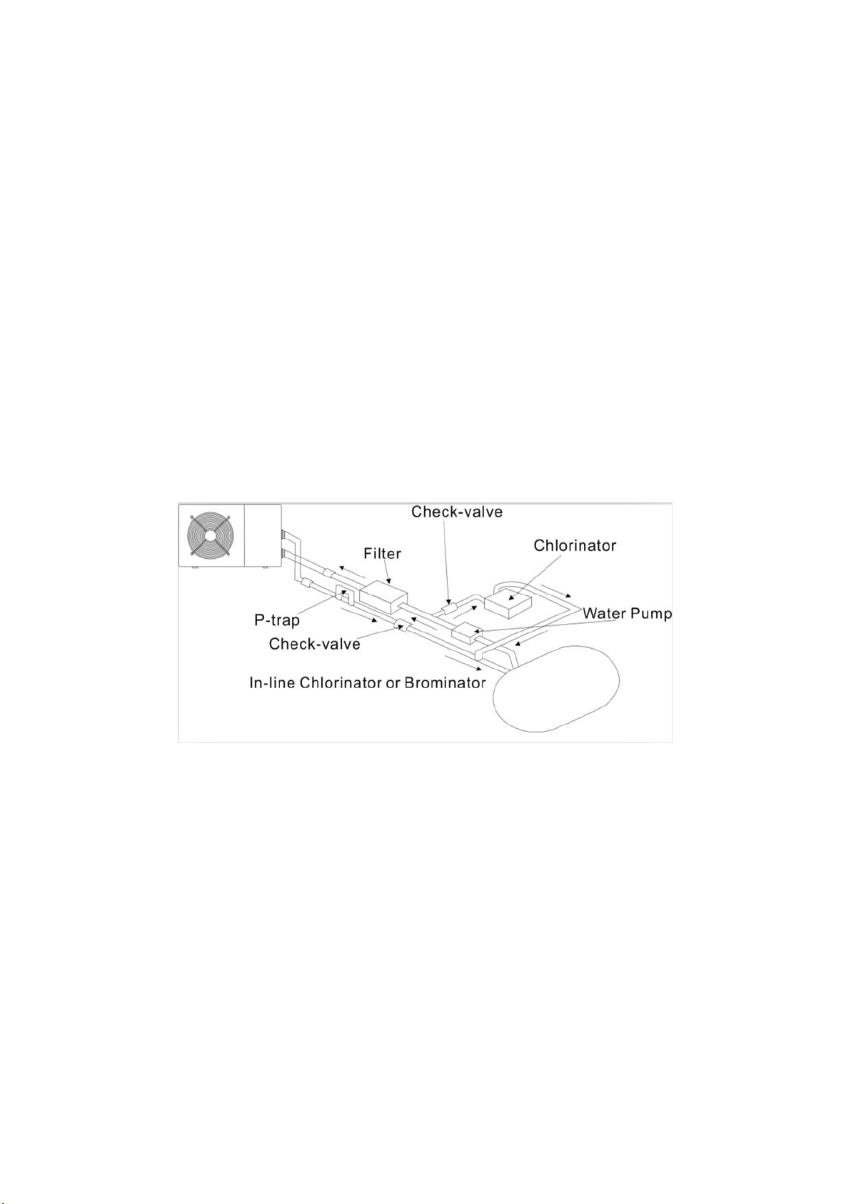
1. Switch on the filter pump. Check for leaks and verify that water is flowing from and to the
swimming pool.
2. Connect power to the heat pump and press the On/Off button on the electronic control
panel. The unit will start up after the time delay expires (see below).
3. After a few minutes, check whether the air blowing out of the unit is cooler.
4. When you turn off the filter pump , the unit should also turn off automatically, if not adjust
the flow switch.
5. Allow the heat pump and the filter pump to run 24 hours a day until the desired water
temperature is reached. The heat pump will stop running at this point. After this, it will
restart automatically (as long as the filter pump is running) whenever the swimming pool
water temperature drops 2 degrees below the set temperature.
Depending on the initial temperature of the water in the swimming pool and the air
temperature, it may take several days to heat the water to the desired temperature. A good
swimming pool cover can dramatically reduce the required length of time.
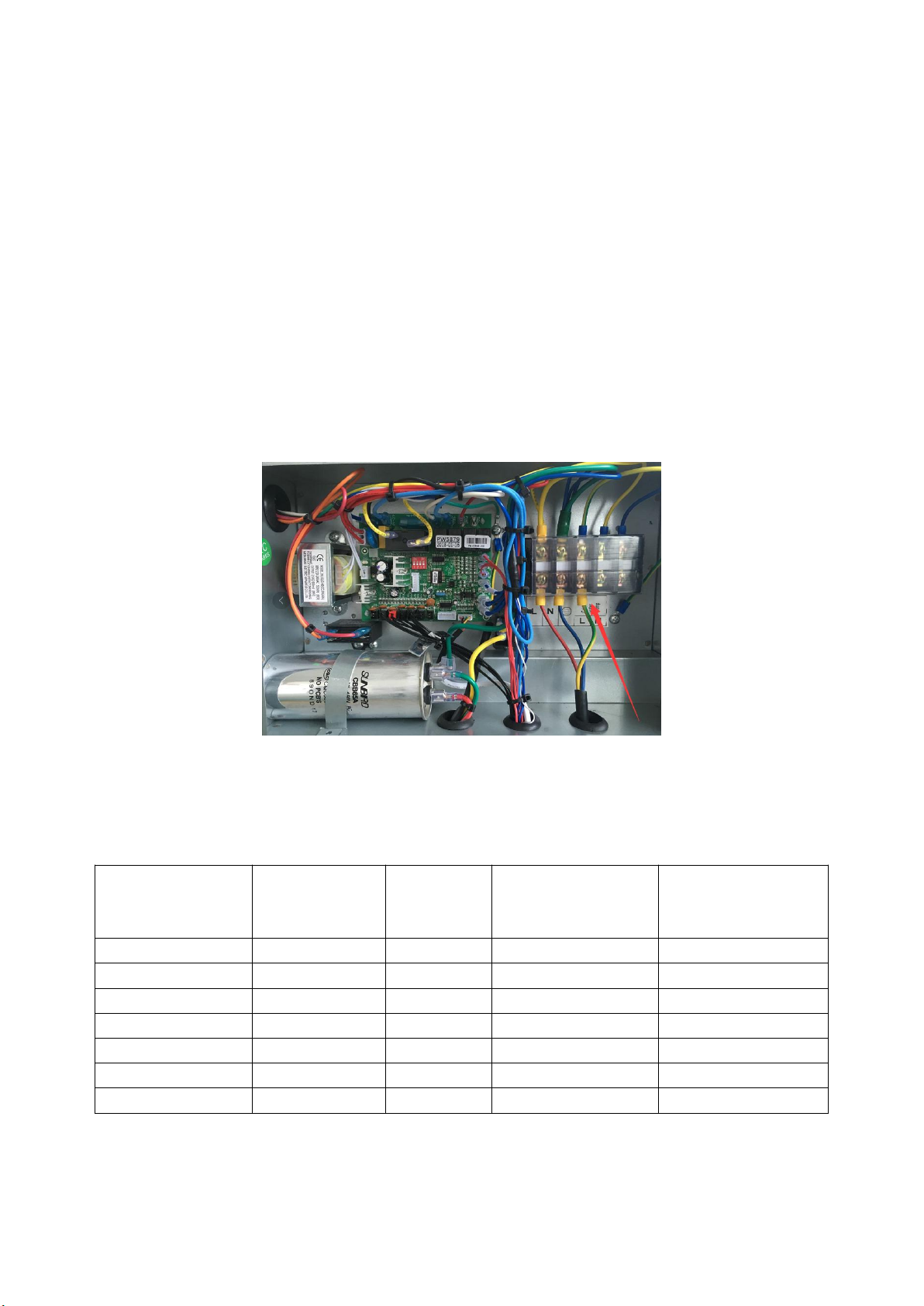
Water Flow Switch:
It is equipped with a flow switch to prevent the heat pump of running with inadequate water
flow rate. It will turn on when the pool pump runs and shuts off when the pump shuts off. If the
pool water level is more than 1m above or below the heat pump’s automatic adjustment knob,
your dealer may need to adjust its initial startup.
Time delay -The heat pump has a built-in 3-minute start-up delay to protect the circuitry and
avoid excessive contact wear. The unit will restart automatically after this time delay expires.
Even a brief power interruption will trigger this time delay and prevent the unit from restarting
immediately. Additional power interruptions during this delay period do not affect the 3-minute
duration of the delay.
3.9 Condensation
The air drawn into the heat pump is strongly cooled by the operation of the heat pump for
heating the pool water, which may cause condensation on the fins of the evaporator. The
amount of condensation may be as much as several litres per hour at high relative humidity.
This is sometimes mistakenly regarded as a water leak.

- 10 -
4. Accessories
4.2 Accessories Installation
Anti-vibration bases
1. Take out 4 Anti-vibration
bases
2. Put them one by one on
the bottom of the machine
like the picture.
Water Inlet & outlet
junction
1. Use the pipe tape to
connect the water Inlet &
outlet junction onto the heat
pump
2. Install the two joints like
the picture shows
3. Screw them onto the
water Inlet & outlet junction
10M Signal wiring
1. Take one side of the 10M
Signal wire, to connect with
the controller.
2. The other side needs to
be pulled through the hole,
like the third picture shows.
3. Then connect to the PC
board inside the machine :
the brown one --- first joint;
the blue one --- second joint;
the yellow one --- third joint.

- 11 -
Cable wiring
1. Connect the power supply
wire through the white hole
like the picture shows.
2. Fix the other side on
joints inside the electric box.
Water pump wiring
1. Connect the water pump
wire through the white
marked hole
2. Fix the other side on
joints inside the electric box.
5. Electrical Wiring
5.1 WiFi SWIMMING POOL HEAT PUMP WIRING DIADRA
PHP 03/06/09/12Hs-W

- 12 -
NOTE:
(1)The above electrical wiring diagrams are only for your reference, please subject the heat
pump to the posted wiring diagram.
(2)The swimming pool heat pump must be earthed well, although the unit heat exchanger is
electrically isolated from the rest of the unit .Earthing the unit is still required to protect you
against short circuits inside the unit .Bonding is also required.
Disconnect: A disconnector (circuit breaker, fused or un-fused switch) should be located
within sight of and easily accessible from the unit .This is common practice on commercial
and residential heat pumps. It prevents remotely-energizing unattended equipment and
permits turning off power to the unit while the unit is being serviced.
6. Display Controller Operation
6.1 The buttons of LED wire controller
When the heat pump is running or standby, the LED display shows the inlet water
temperature and setting temperature.
6.2 Start/stop the heat pump.
Press to start the heat pump, the LED display shows the desired water temperature for
5 seconds, then shows the inlet water temperature.

- 13 -
Press to stop the heat pump.
6.3 Choose heating/cooling/Automatic mode:
Press until “heat” or “Cool” “Automatic” light is on.
6.4 Setting the real time
Timer button: used for clock and timing setting
Touch button to enter clock setting, the clock at the bottom flashing to enter the clock Settings,
if need set the clock, click on the button to enter the hours setting, combine button to change
the hour Settings, after setting completed, and then click on the button to enter the minutes setting,
combined with change the minutes Settings, set up is completed, press complete set and
return to main interface.
6.5 Water temperature setting:
On standby or running mode, press to adjust the desired water temperature
6.6 Automatic start/stop of the heat pump
Long press button, enter the time setting for group 1 timing on/off settings, click the button to enter
hours setting, press or button to change the time, after setting completed, click the button
to enter minutes setting, press or button to change the time,after setting completed , click on the
button to enter regular shutdown Settings, set method is same with timing setting, after setting
completed,click the to enter next group setting. Same setting method based on above operation.
During timing setting state , click the to cancel current timing setting.
During the the main interface ,Press to set the current mode’s setting
temperature.

- 14 -
6.7Running data query and setting
Long press button to enter parameters query state, in the query conditions click the button to enter
parameter setting state, combined with and button to change the parameter value, press button again
to determine modification, During the parameter query condition press the button to return the main interface;No
operation is retained in the query condition.
Special note:
During Automatic mode, the icon is displayed;
During Cooling mode, icon is displayed ;
During Defrosting , icon is displayed;
During Heating mode, icon is displayed;
ICONS are used to identify the WIFI signals, its twinkle when its not connect with the server; its keeps on means
connection well .
7、System Parameter:
Parameter
Meaning
Range
Default
Remarks
P00
Memory function
0(No)\1(Yes)
1
Adjustable
P01
Operate at set time everyday
0(No)\1(Yes)
1
Adjustable
P02
Water temperature difference back
to restart
2-10℃
3
Adjustable
P03
Water Temperature difference to
stop
0-3℃
0
Adjustable
P04
Defrosting interval
30-90Min
40Min
Adjustable
P05
Defrosting on temperature (evaporator
coil temperature)
-30—0℃
-3℃
Adjustable
P06
Defrosting exit temperature
(evaporator coil temperature)
2-30℃
13℃
Adjustable
P07
Defrosting exit time
1-15Min
8Min
Adjustable
P08
Gas exhaust temperature protection
value
95-120℃
118℃
Adjustable
P09
Max. water set temperature
40~65
40
Adjustable
P10
Water pump operation mode
0(Special)\1
(Normal)
1
Adjustable
P11
Water pump stop time after reaching
water set temperature
3-20min
15
Adjustable
P13
Heating/Cooling option
0(Single cooling)/
1
Adjustable

- 15 -
1(Heating/Cooling)/
2(Single heating)
P14
Electronic expansion valve action cycle
20s~90s
30s
Adjustable
P15
Degree of super heat setting
-9℃~9℃
3℃
Adjustable
P16
expansion valve forced opening gas
exhaust temperature
80℃~110℃
100℃
Adjustable
P17
Electronic expansion valve opening
setting (under defrosting)
20~450P
400P
3 digits visible
P18
Electronic expansion valve minx.
Opening setting
50~200P
150P
3 digits visible
P19
Electronic expansion valve manual
setting
20~450P
350P
Adjustable
P20
Electronic expansion valve manual
setting option
0 (No) /1(Yes)
1
0:manual/1:
automatical
P22
expansion valve forced opening gas
exhaust temperature
80℃~110℃
100℃
Adjustable
A0
Water inlet temperature
-9~99℃
Actual
measurement
A1
Water outlet temperature
-9~99℃
Actual
measurement
A2
Evaporator coil temperature (under
heating mode)
-9~99℃
Actual
measurement
A3
Gas exhaust temperature
-9~99℃
Actual
measurement
A4
Ambient temperature
-9~99℃
Actual
measurement
A5
Gas suction temperature
-9~99℃
Actual
measurement
A6
Expansion valve opening
150~480P
Actual
measurement
8. Troubleshooting
8.1 Error code display on LED wire controller
Malfunction
Error code
Solutions
Heating condenser sensor failure
Er P1
Check or change the sensor
Exhaust temperature sensor failure
Er P2
Check or change the sensor
Inlet water temperature sensor failure
Er P3
Check or change the sensor
Outlet water temperature sensor failure
Er P4
Check or change the sensor
Ambient temperature sensor failure
Er P7
Check or change the sensor
Gas return sensor failure
Er P8
Check or change the sensor
Low pressure protection
Er P9
1.Check if there is any gas leakage ,re-fill the
refrigerant
2.Replace the filter or capillary

- 16 -
First grade antifreeze protection in Winter
Er PC
Water pump will run automatically for first grade
antifreeze
Second grade antifreeze protection in
Winter
Er PC
Heat pump will start heating for second grade
antifreeze
Water flow switch
Er PL
Check water flow /switch
Exhaust temperature too high protection.
Er 3
1. Replace the compressor discharge temperature
sensor.
2. Reconnect or clean compressor discharge
temperature sensor and wrap it with insulation
tape.
3. Replace the controller or PC Board.
High pressure protection
Er 4
1. Discharge redundant refrigerant from heat
pump gas system
2.Clean the water exchanger or water fifter
Communication failure
Er 8
Check the wire connection
Defrosting
Defrost
instructions
8.2 Other Malfunctions and Solutions (No display on LED wire controller)
Malfunctions
Observation
Reasons
Solution
Heat pump is
not running
LED wire controller shows
no display
No power supply
Check whether cable and
circuit breaker are
connected
LED wire controller
displays the actual time
Heat pump under standby
status
Startup heat pump to run.
LED wire controller
displays the actual
water temperature
1. Water temperature is
reaching set value, heat pump
under constant temperature status
2. Heat pump just starts to run
3. Under defrosting
1. Verify water temperature
setting
2. Startup heat pump after
a few minutes
3. LED wire controller
should display "Defrosting"
Water
temperature is
cooling when
heat pump runs
under heating
mode
LED wire controller
displays actual water
temperature and no error
code displays
1. Chose the wrong mode
2. Figures show defects
3. Controller defect
1. Adjust the mode
2. Replace the defect LED
wire controller, and then
check the status after
changing the running
mode, verifying the water
inlet and outlet temperature
3. Replace or repair the
heat pump

- 17 -
Short running
LED displays actual water
temperature, no error code
displays
1. Fan NOT running
2. Not enough air ventilation
3.Not enough refrigerant
1. Check the cable
connections between the
motor and fan, if
necessary, they should be
replaced
2. Check the location of the
heat pump, and eliminate
all obstacles to assure a
good air ventilation
3 Replace or repair the
heat pump
water stains
Water stains on heat pump
unit
1. Concreting
2. Water leakage
1. No action
2. Check the titanium heat
exchanger carefully if it
shows any defects
Too much ice
on evaporator
Too much ice on
evaporator
1. Check the location of
heat pump, and eliminate
all obstacles to assure a
good air ventilation
2. Replace or repair the
heat pump
9. Maintenance
(1) You should check the water supply system regularly to avoid the air entering the system
and occurrence of low water flow, because it would reduce the performance and reliability of
the heat pump.
(2) Clean your pools and filtration system regularly to avoid the damage of the unit as a result
of a dirty or clogged filter.
(3) You should discharge the water from the bottom of the water pump if the heat pump will
stop running for a long time (specially during the winter season).
(4) On any other moment, you should check if the unit has enough water before the unit
starts to run again.
(5) After the unit is conditioned for the winter season, it is preferred to cover the heat pump
with the special winter heat pump cover.
(6) When the unit is running, there is allways a little water discharge under the unit.

- 18 -
WIFI Controller Function Specification
1、Android WIFI Module Set Up Steps:
Scan the QR code to download or use the below link:
https://fir.im/124b to download and operate based on below steps .
Step 1:
Turn it on,when the drive by wire controller is out of full screen,buzzer rings
a sound like “Di”, it shows to be in the AP mode. Only when being in the AP mode,
the heat pump can be equipped with the WIFI module;
Enter the AP mode by hand(Press the button of ++for 3 seconds in the
same time. When entering the AP mode, the button is twinkling;
Step 2:
Turn on the WIFI on phone and get it connected to the WIFI hot spot,the WIFI hot
spot should be connected to the internet,show on the picture:Connected to WIFI
hot spot“TP-LINK_1906”;

- 19 -
Step 3:
Open the APP on the phone, type the account and password to login like the pictures
below.(If without account, register one according to the link at the bottom)
Successfully login in the main interface of server, like the picture shows:
Step 4:
Click the " AP mode " to search the swimming pool WIFI signal
Note: if the wireless network signal is not found, please slide the screen to search
again!

- 20 -
Select the pool machine WIFI signal and connect, such as: connect the pool machine
WIFI signal "Z_088810"; Enter the correct WIFI password, according to the
determination of the connection.
Step 5:
After a successful connection to WIFI signal for the pool machine, the system can
be used normally
This manual suits for next models
7
Table of contents