Harol BX270 User manual

Harol NV – Industriepark 3 – 3290 Diest – Belgium - +32 (0) 3 38 0 – info@harol.be – www.harol.com
Art. nr.: 050442 V03-04/ 8
Vervangen van de voeding en ontvanger voor LED-verlichting bij BX270
Art. nrs.: 050 36 - Set voeding BX270 LED - standaard
050 37 - Set voeding + ontvanger BX270 LED – RTS
050 38 - Set voeding + ontvanger BX270 LED – IO
063859 - Set voeding + ontvanger BX270 LED – IO dimbaar
Gebruik de test LED strip om de werking van de voeding te controleren.
Zorg dat het scherm steeds volledig spanningsloos is als je aan de elektrische verbindingen werkt.
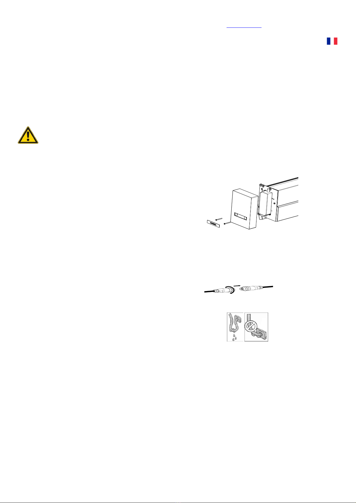
. Verwijderen bestaande voeding en ontvanger:
a. Verwijder de zijkap door de schroeven
achter het HAROL logo los te schroeven,
zodat de voeding en eventueel ontvanger
vlot bereikbaar zijn.
b. De connector en kabels losmaken aan de
24V en 230V zijde.
c. Verwijder de defecte voeding/ontvanger.
2. Nieuwe voeding/ontvanger plaatsen:
a. Zijplaat zuiver maken en voeding
vastschroeven.
b. Eventueel ontvanger vastkleven of
bevestigen met een colsonbandje.
c. Verbind de 24V uitgang met de ledstrip
via de connector.
d. 230V aansluiten, er is 3m kabel
voorzien.
e. Zijkap en HAROL logo terugplaatsen.
3. Testen
Zet de spanning terug op en test de installatie.
Volg de handleiding van de zender om de ontvanger terug in te leren.
Harol NV – Industriepark 3 – 3290 Diest – Belgium - +32 (0) 3 38 0 – info@harol.be – www.harol.com
Art. nr.: 050442 V03-04/ 8
Remplacement de l'alimentation et du récepteur pour l’éclairage à diodes
électroluminescentes de BX270
N° art. : 050 36 - Set alimentation BX270 LED - standard
050 37 - Set alimentation + récepteur BX270 LED – RTS
050 38 - Set alimentation + récepteur BX270 LED – IO
063859 - Set alimentation + récepteur BX270 LED – IO Dim.
Utilisez la bande de diodes électroluminescentes de test pour contrôler le fonctionnement de l'alimentation.
Veillez à toujours mettre le store entièrement hors tension lorsque vous travaillez sur les connexions
électriques.
. Ôter l'alimentation et le récepteur existants :
a. Ôtez le couvercle latéral en desserrant les
vis derrière le logo HAROL, de manière à
pouvoir accéder facilement à
l'alimentation et au récepteur éventuel.
b. Détachez le connecteur et les câbles des
côtés 24V et 230V.
c. Ôtez l'alimentation/le récepteur
défectueux.
2. Poser une nouvelle alimentation/un nouveau
récepteur :
a. Nettoyez le couvercle latéral et vissez
l'alimentation.
b. Collez ou fixez le récepteur éventuel avec un
collier de serrage.
c. Raccordez la sortie 24V à la bande de
diodes électroluminescentes via le
connecteur.
d. Branchez 230V, un câble de 3 m est
prévu.
e. Remettez en place le couvercle latéral et le
logo HAROL.
3. Vérification du fonctionnement
Remettez la tension et testez le fonctionnement de l'installation.
Suivez le manuel de l'émetteur pour procéder de nouveau à la détection du récepteur.

Harol NV – Industriepark 3 – 3290 Diest – Belgium - +32 (0) 3 38 0 – info@harol.be – www.harol.com
Product no: 050442 V03-04/ 8
Replacing the power supply and receiver for LED lighting with BX270
Prod. Nos.:
050 36 - Set power supply BX270 LED - standard
050 37 - Set power supply + receiver BX270 LED – RTS
050 38 - Set power supply + receiver BX270 LED – IO
063859 - Set power supply + receiver BX270 LED – IO dimmable
Use the test LED strip to check that the power supply is working.
Ensure the power to the awning is always completely switched off when working on the electrical connections.
. Removing the existing power supply and receiver:
a. Remove the side guard by unscrewing the
screws behind the HAROL logo, so that the
power supply, and if present, the receiver
are easily accessible.
b. Disconnect the connector and cables on
the 24V and 230V side.
c. Remove the faulty power supply/receiver.
2. Fitting the new power supply/receiver:
a. Clean pulley plate and tighten power supply
screws.
b. If necessary, glue the receiver or attach with
a Colson cable tie.
c. Connect the 24V output with the LED
strip via the connector.
d. Connect 230V, 3m cable has been
provided.
e. Put back the side guard and HAROL logo.
3. Testing
Turn the power back on and test the system.
Follow the sender guide to incorporate one or more receiver controls.
Harol NV – Industriepark 3 – 3290 Diest – Belgium - +32 (0) 3 38 0 – info@harol.be – www.harol.com
Art. nr.: 050442 V03-04/ 8
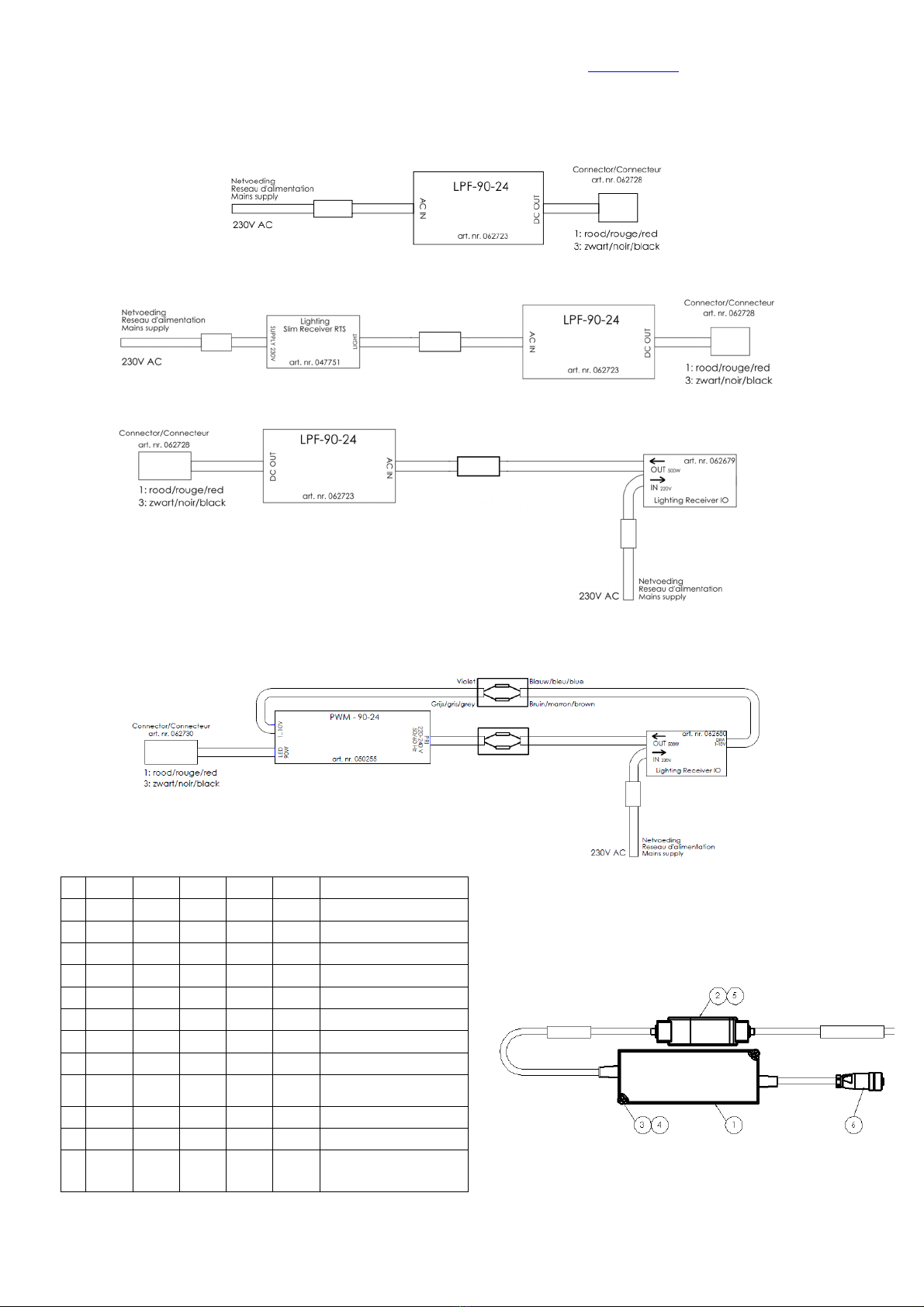
Elektrische schema’s / Schémas électriques / Electrical diagrams
. LED verlichting – Standaard / Éclairage LED – Standard / LED lighting – Standard
2. LED verlichting – RTS bediening / Éclairage LED – Commande RTS / LED lighting – RTS controls
3. LED verlichting – IO bediening / Éclairage LED – Commande IO / LED lighting – IO controls
4. LED verlichting – Dimbare IO bediening / Éclairage LED – Commande IO avec réglage de l’intensité /
LED lighting – Dimmable IO controls
8 50442
1 1 1 1 Handleiding / manual
7 50440
1 1 1 1 Test LED strip
6 62728
1 1 1 1 Connector
62723
- - 1 1 Colson strap
5 62784
- 1 - - Tape
4 2275 2 2 2 2 DIN 125 - M4
3 44262
2 2 2 2 DIN 7985 - M4 x 6
62680
- - - 1
Lighting receiver IO dim
62679
- - 1 - Lighting receiver IO
2 47751
- 1 - -
Lighting slim receiver
RTS
50255
- - - 1 Voeding PWM-90-24
1 62723
1 1 1 - Voeding LP -90-24
N°
Art.
N° 50436
50437
50438
63859
Omschrijving /
Description
Stuklijst / BOM / Bill of materials
Table of contents
Languages:


