Harol SC900 User manual

INSTALLATION INSTRUCTIONS
SUN PROTECTION
PROTECTION SOLAIRE
SHUTTERS
VOLETS
GATES
PORTES
SURFACE-MOUNTED SCREEN
SC900 - SC910
art.no. 60447

INSTALLATION INSTRUCTIONS SURFACE-MOUNTED SCREEN SC900 - SC910
03/15 |2
TABLE OF CONTENTS
1. INTRODUCTION 3
2. GENERAL WARNINGS 3
3. LIST OF TOOLS REQUIRED 4
4. INSTALLATION STEPS 5
4.1. Determine the type of screen 5
4.2. Check the package 5
4.3. Check the product 5
4.4. Check the height and width 5
4.5. The actual assembly in 10 steps 6
4.6. Installation of two or more adjacent screens 14
4.7. Checking the assembly 16
5. ELECTRICAL CONNECTIONS 17
5.1. Connection diagram for a single pole switch 17
5.2. Adjusting the motor - limit switches 18
6. TROUBLESHOOTING AND REPAIRS 20
6.1. The screen will not roll up or down 20
6.2. The motor hums 20
6.3. The motor does not stop in time 20
6.4. Bottom lath is slanted at the top 20
6.5. Bottom lath drops out of the lateral guides 20
6.6. The fabric tension is too slack; the bottom lath sticks
or shudders when the screen is lowered or raised 20
6.7. Folds and waves in the fabric 20
6.8. The direction of the motor’s rotation does not match the arrows on the switch 20
6.9. The fabric does not stop and roll up again 20
6.10. Automatic control does not operate properly 21
6.11. The bottom lath sticks or shudders when the screen is lowered or raised 21
7. REPAIRS 21
8. DISMANTLING AND REMOVAL 21
9. NOTES 22

INSTALLATION INSTRUCTIONS SURFACE-MOUNTED SCREEN SC900 - SC910
03/15 |3
1. INTRODUCTION
The SC900 screen is a flat hanging sun screen, which is fitted on top of the window with
a'zipper system' on each side of the fabric. This makes the screen particularly resistant to high
winds and keeps the fabric perfectly in place. In the down position the screen keeps out the
sun's rays, which can cause overheating, while at the same time it gives a view to the outside.
Moreover, this screen oers practical protection against insects, as the space between the
box, the guide rails and the fabric is completely sealed o.
The SC900 can also be fitted with fabrics that are almost fully opaque, making it especially
suitable to black out presentation rooms in oce buildings, laboratories, hospitals etc.
The installation of this sun protection system is explained step by step in these instructions.
The SC910 screen is a flat hanging sun screen with the same properties, but without the
insulation and cover (for the box). It is basically a 'naked' version of the SC900 screen.
Attention!
Open box, standard version without the back covered. This version requires a suitable
finish to avoid damage to and prevent dirt from settling on the fabric. (possible option =
full support plate instead of brackets)
2. GENERAL WARNINGS
A number of precautions have to be taken for the safe installation, operation and maintenance
of this screen. Please take notice of the following warnings for the safety of everyone concerned!
!These instructions have been drawn up for use by trained installers and therefore are
not suitable for use by amateurs or trainees.
!Please read these instructions carefully before starting the installation.
!Proceed carefully. Ensure that you have a robust footing.
!Make sure there is adequate lighting in the place of assembly. Remove any obstacles
and dirt. Ensure that no other persons other than the installers are present.
Unauthorised persons can get in the way or be at risk during the installation.
!The screen must be kept clearly in view at all times during installation and operation.
Persons in the vicinity may be at risk of injury.
!The installer must comply with the local regulations and standards with regards to
electrical connections.
!Our products must be installed in such a way that all parts remain accessible at all times
for maintenance and repairs. If this is not the case, Harol cannot be held responsible for
any additional costs (e.g. demolition work, repairs to exterior or interior walls) whichmay
result from this.

INSTALLATION INSTRUCTIONS SURFACE-MOUNTED SCREEN SC900 - SC910
03/15 |4
Guarantee, terms and conditions
• Harol has endeavoured to design and manufacture the screen in compliance with
the current CE standards. Always check that our version complies with your own
national standards institute.
• No rights can be derived from these instructions whatsoever. Technical modifications
are reserved without written notification.
• For large projects we strongly advise you to first fit 1 complete awning before fitting
the remaining awnings. This will help detect any potential faults early on and enable
them to be remedied at the lowest possible cost.
• For our general terms and conditions of sale, please refer to the price list.
• Make sure the screen box can always be opened so the mechanical parts inside can
be reached easily. If these rules are not respected, Harol cannot be held responsible
for the cost of demolition work or any paint work or wallpapering.
Harol NV
Industriepark 3 – 3290 Diest
Belgium
+32 (0)13 38 01 11
+32 (0)13 31 48 03
info@harol.be
www.harol.com
3. LIST OF TOOLS REQUIRED
• Ladder(s)
• Tape measure and pencil
• Cross-slotted screwdrivers
• Spirit level, plumb line or water hose
• Drill
• Set of drills
• Voltage meter or 220 V testing lamp

INSTALLATION INSTRUCTIONS SURFACE-MOUNTED SCREEN SC900 - SC910
03/15 |5
4. INSTALLATION STEPS
4.1. Determine the type of screen
Check the type of screen: SC900 (with insulation) or SC910 (without insulation)
4.2. Check the package
Check the package for any damage before removing the complete packaging from around
the box and guide rails.
4.3. Check the product
Check the product: ensure all guide rails and clip profiles are included and check if each
guide rail contains a holder with zipper profile.
Also check the bag with accessories. Verify that the screws for securing the support plate,
the clips for the bottom profile and the screws for securing the clip and bottom profiles
are there, together with the guarantee card.
4.4. Check the height and width
Check the width of the screen box and measure the window opening.
Verify that both match the desired mounting position.
Also check the height of the guide rails, including the end stop, and make sure they
correspond to the height of the window.
In the following steps logos are used to show the dierence between mounting the SC900
and SC910 screens.
SC900 SC910

INSTALLATION INSTRUCTIONS SURFACE-MOUNTED SCREEN SC900 - SC910
03/15 |6
4.5. The actual assembly in 10 steps
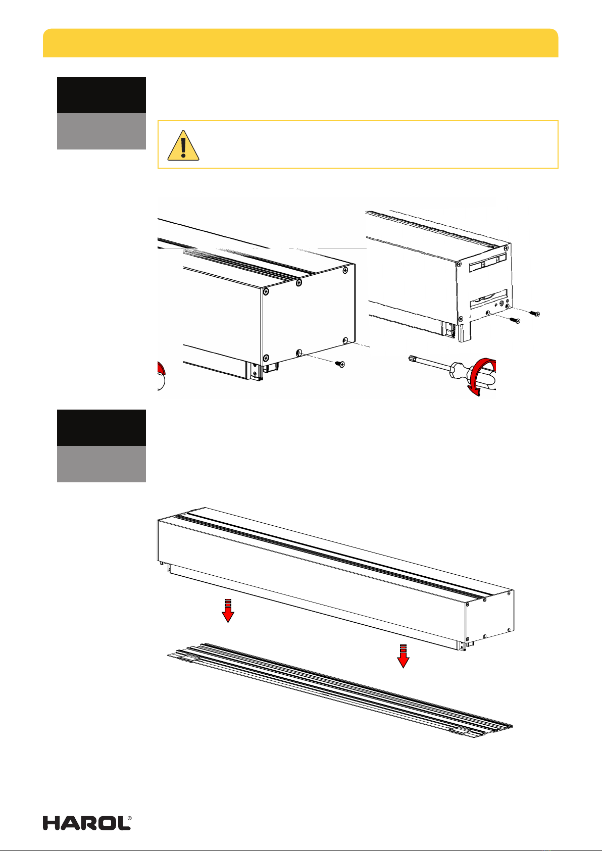
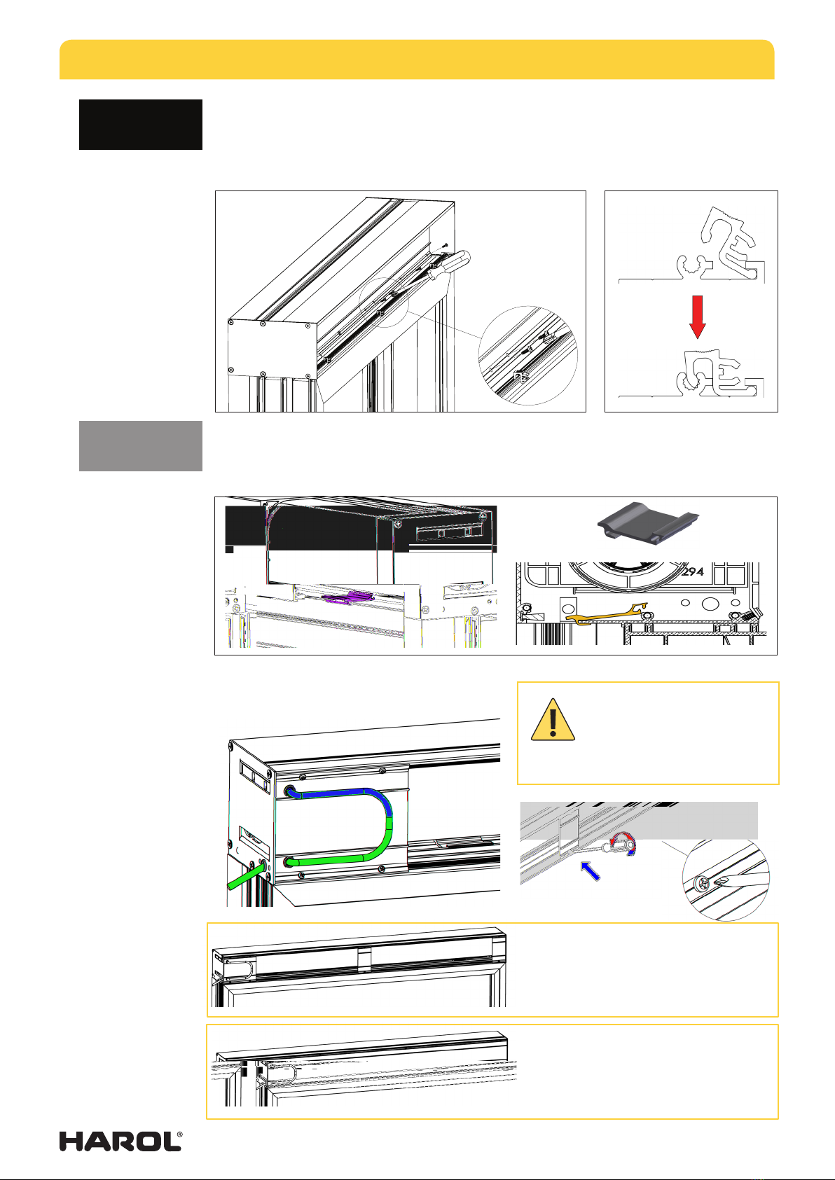
Step 1
• Remove the cover and the insulation.
• (SC900) The support plate and base plate are connected. The advantage of thisis
that the base plate does not bend when handling the box. Remove these screws
before mounting the screen!
• (SC910) Unscrew the brackets or support plate (optional) at the bottom, to free the
base plate.
SC900
SC910
SC900
SC900 SC910
INSTALLATION INSTRUCTIONS SURFACE-MOUNTED SCREEN SC900 - SC910
03/15 |7
• Then unscrew the two screws at the back that connect to the base plate.
Step 2
• Carefully let the base plate slide from the box.
Please note that this operation must be carried out on both sides of the box
before proceeding to the next step.
SC900
SC910
SC900
SC910
INSTALLATION INSTRUCTIONS SURFACE-MOUNTED SCREEN SC900 - SC910
03/15 |8
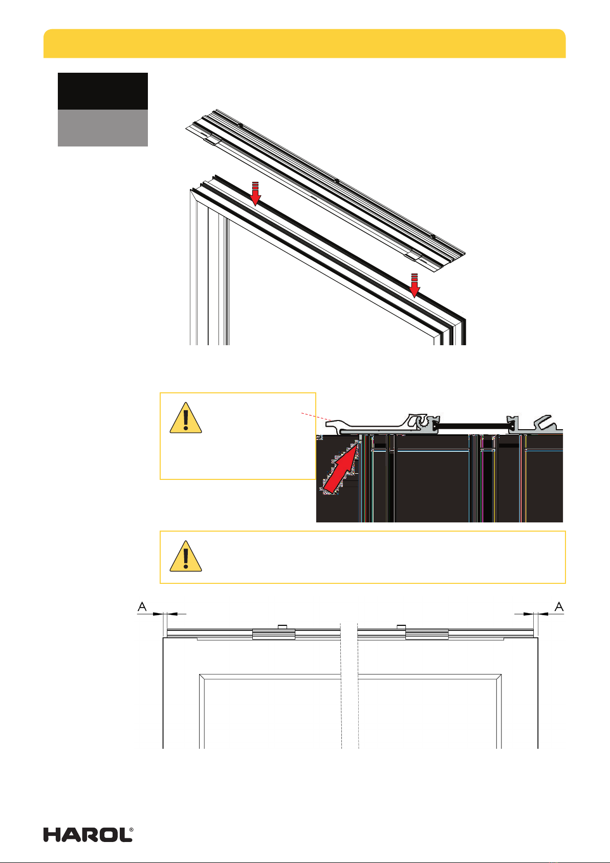
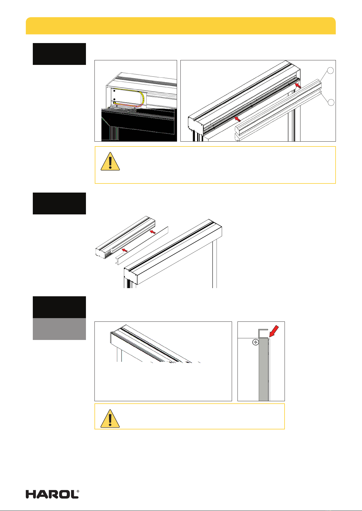
Step 3
• Centre the base plate on the window and screw it down.
• Make sure the base plate is correctly centred on the window.
• Distance (A) must be the same on both sides.
Tab at the bottom of the base profile forms the abutment with the window.
SC900
SC910
The touch component
for the bottom lath of
the SC910 screen is supplied
separately. This is mounted on
the base plate at a later stage!
INSTALLATION INSTRUCTIONS SURFACE-MOUNTED SCREEN SC900 - SC910
03/15 |9
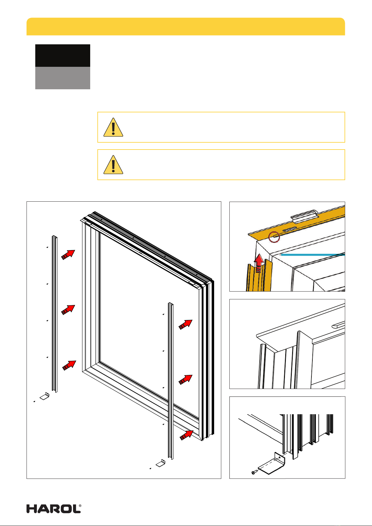
Step 4
• Attach the clip profiles with the hole in a downward position.
• First position the upper side of the clip profile against the tab on the bottom side of
the base plate (Fig. 1a-1b).
• Next, drill holes at regular intervals to secure the clip profile and attach it to the window.
• In the bottom pre-drilled hole, the clip profile must be secured together with the end
stop (Fig. 2).
Make sure the clip profiles are mounted perpendicular, and check the diagonals
(see 4.6).
There is a hole in the clip profile to secure the end stop (Fig. 2).
Fig. 1a
Fig. 1b
Fig. 2
SC900
SC910

INSTALLATION INSTRUCTIONS SURFACE-MOUNTED SCREEN SC900 - SC910
03/15 |10
Step 5
• Clip both lateral guides - together with the holder with zipper profile - onto the
clipprofile.
• No screws are required!
Plan view of the clip profile
and guide rail
SC900
SC910
INSTALLATION INSTRUCTIONS SURFACE-MOUNTED SCREEN SC900 - SC910
03/15 |11
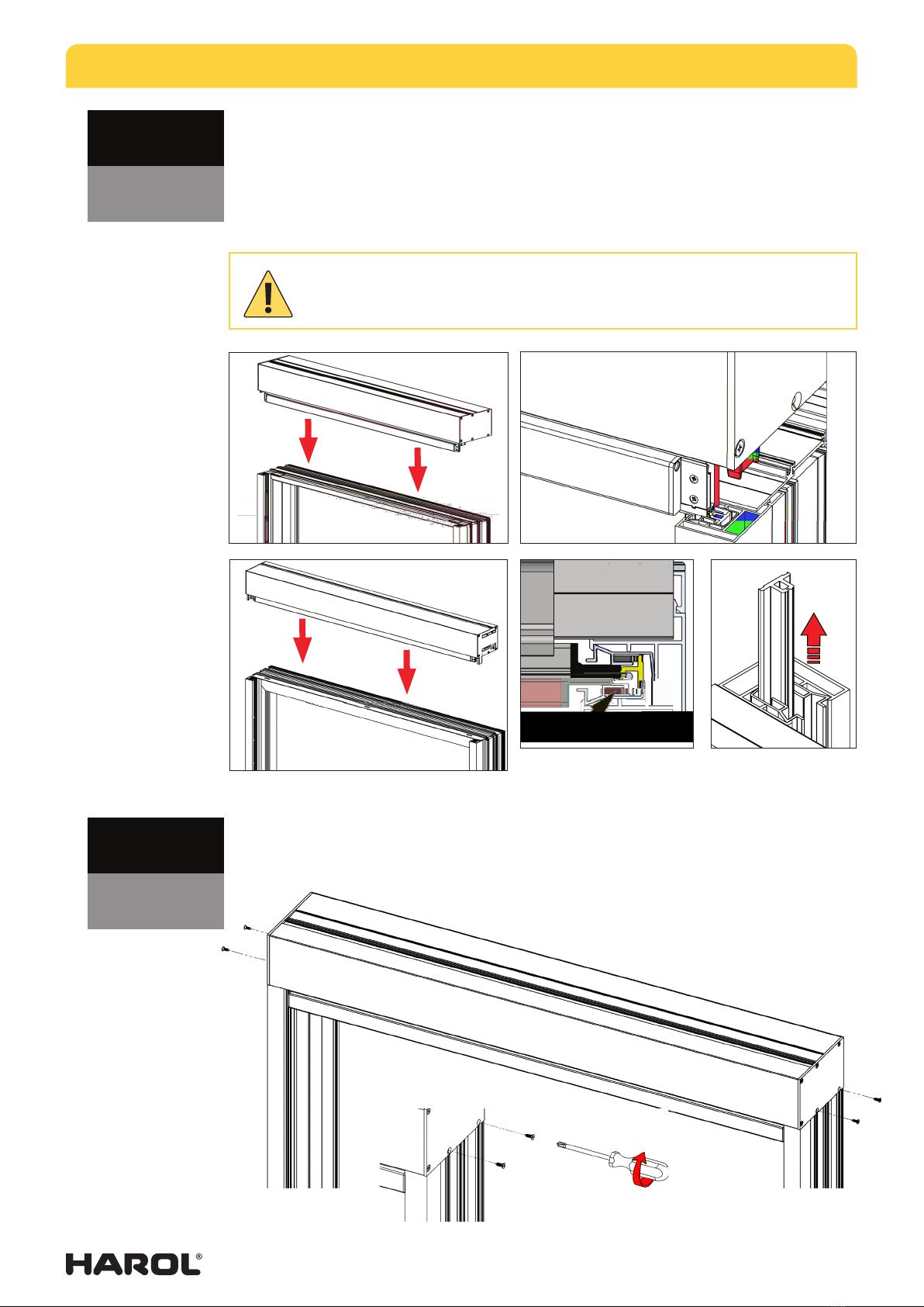
Step 6
• Place the box back on the base profile exactly as it was initially constructed (Fig. 3a-3b)
(see Step 1).
• Guide the bottom lath to the zipper guide profile, position the zipper in the zipper
guide profile and let it drop down (Fig. 5).
• To make it easier to slide the fabric zipper into the zipper profile, slide the zipper
guide upwards, so it is very slightly out of the holder (Fig. 6).
Step 7
• Screw the box back onto the base plate.
Pay attention when positioning the pin in the lateral guide and sliding the zipper
into the zipper guide (Fig. 4)! Make sure the zipper is placed correctly in the
zipper guide.
Fig. 3a
SC900 Fig. 4
Fig. 5
Fig. 6
SC900
SC910
Fig. 3b
SC910
SC900
SC910
INSTALLATION INSTRUCTIONS SURFACE-MOUNTED SCREEN SC900 - SC910
03/15 |12
Step 8
• Use the supplied screws to screw the bottom of the support plate to the base plate
(Fig 7).
• Position the supplied clips into the base profile and clip until fastened (Fig. 8).
• Now insert the supplied touchers for the bottom lath at approx. 100 mm from the sides
and clip to secure (Fig 9). For better accessibility lower the fabric.
• Tighten the supports with the supplied
screws (Fig 7).
Fig. 8
Fig. 7
SC900
SC910
Fig. 7
Fig. 9
Always provide a loop for
securing the motor cable.
This loop determines the
available movement of the
insert module! (Fig. 8.)
STANDARD cover for the box.
Ensure that the fabric is protected when
finishing the work!
OPTION
Complete support plate as cover for the box.
The fabric is fully protected by the
supportplate
Fig. 8
INSTALLATION INSTRUCTIONS SURFACE-MOUNTED SCREEN SC900 - SC910
03/15 |13
Step 9
• Place the thermal insulation blocks back in the box.
Step 10
• Close the box with the cover, push it down and secure with the appropriate clips
(seeStep 8).
Step 11 finishing profiles (optional)
• Glue down the supplied finishing profiles. One on each side console (small profiles)
and one length at the top of the box (flush with the cover profile!).
Window anchors
In order to fix the box into the wall recess, the following window anchor types can be used:
for the SC900 a minimum length of 160 mm is required.
− ALIPLAST ACVL 130 (160x38x2).
− REYNAERS window cl. Fulchs 439.119 (200x25x2) - available from Harol (optional).
Leave cover unobstructed! (SC900)
SC900
SC900
SC910
- First position the bottom (1) insulation profile and then the top one (2) (Fig. 10).
- Provide a cable wrap (loop) of approximately 20 cm in the chamber furthest
back (Fig. 9). In the event of subsequent maintenance or repair, the insert
module can be taken out of the box.
Fig. 9
1
2
SC900
Fig. 10

INSTALLATION INSTRUCTIONS SURFACE-MOUNTED SCREEN SC900 - SC910
03/15 |14
4.6 (a). Installation of two or more adjacent screens
Step 1
• Mount box uaccording to the prescribed installation procedure.
INSTALLATION INSTRUCTIONS SURFACE-MOUNTED SCREEN SC900 - SC910
03/15 |15
SC910
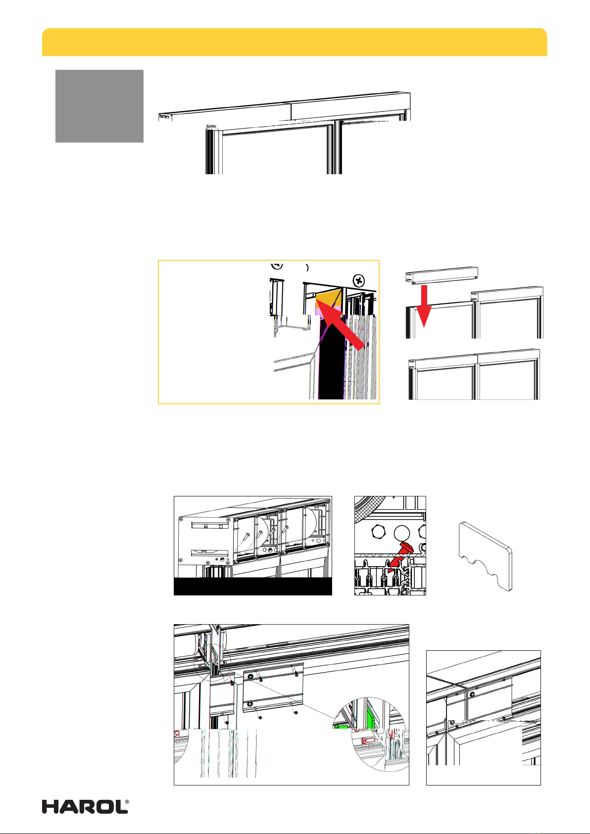
4.6 (b). Installation of two or more adjacent screens
Step 1
• Mount box uaccording to the prescribed installation procedure.
Step 3
• Position box v onto the mounted guide rails (Fig. 15), and slide the bottom lath/fabric
into the zipper guides. Screw the screen onto the window profile (Fig. 16a - 16b).
• Connect both screens using the supplied bolts and intermediate plate (Fig. 17).
Step 2
• Mount the guide rails for the second/next box vonto the window.
uv
• Finally, fit the supports plates (Fig. 18).
fig. 16b
fig. 17
fig. 17b
fig. 15
adjacent
fig. 16a
In order to determine the
correct position of the
second guide rail, secure
the second box onto
the window. The correct
position of the guide rail is
determined by the recess
in the base plate toucher.
fig. 17a
fig. 16b

INSTALLATION INSTRUCTIONS SURFACE-MOUNTED SCREEN SC900 - SC910
03/15 |16
−4.7. Checking for squareness
Make sure that the screens are always dead
level and installed perfectly square. This can
be checked and corrected in one way only.
1. Check first whether the whole
assembly is mounted dead level.
2. Check whether the guide rails
run parallel and perpendicular
to the box. Measure the distance
between the guide rails exactly
and to the millimetre. Begin
directly under the box. Deviations
of more than 2 mm can lead to
hitches with the screen and/or
bottom lath and the fabric may
not hang suciently taut.
3. Next measure accurately across
the diagonals, down to the exact
millimetre.
If the box and guide rails are not correctly fitted, then the bottom lath may roll up askew
into the box and the screen cloth will have diagonal or crosswise creases.
Once the screen has been accurately positioned and fitted, the potential small openings
between guide rails and wall (box and wall) can be sealed with silicon mastic.
4.8. Checking the assembly
The assembly is checked by testing its functionality.
The fabric is lowered and rolled back up. This should happen without any hitches and there
should be no pleats when let down again.
B1= B 2and D1= D2
B2
B1
D1 D2
INSTALLATION INSTRUCTIONS SURFACE-MOUNTED SCREEN SC900 - SC910
03/15 |17
5. ELECTRICAL CONNECTIONS
Note: The connections must be carried out by a registered installer (refer to guarantee card
2.1.) Electrical installation and connection diagrams must be applied correctly, the electrical
accessories employed must comply with the current standards and/or requirements.
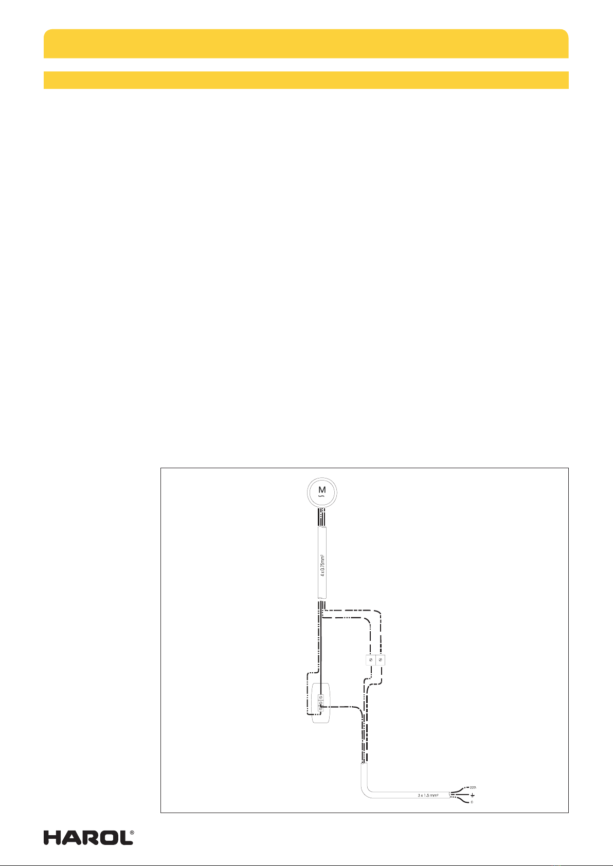
5.1. Connection diagram for a single pole switch
The motor has 4 wires. Yellow-green (earth), blue (neutral), brown and black (up and down
control). There should be three wires available from the mains electricity circuit. Yellow-
green (earth), blue (neutral) and phase. Connect the wires following the diagram. The phase
wire of the mains is to be connected to terminal L.
If required, reverse the brown and black wires from the motor in the switch so that the
arrows correspond to the up and down movement of the screen. The two earthing wires
are interconnected by means of separate terminals. The arrangement for the two neutral
wires is similar.
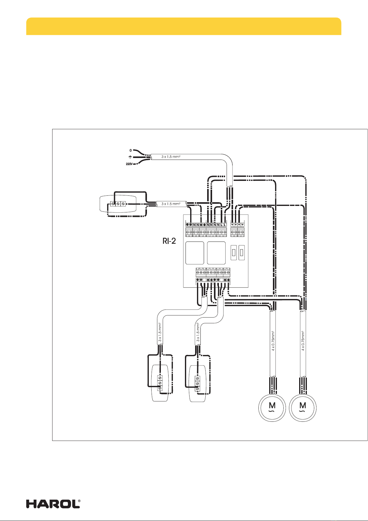
Connecting and installing the motor:
Feed the motor cable in a discreet manner into the control switch. Connect the motor
cable and the power supply to the single pole switch. See above. Interchange the brown
and black cable if necessary to follow the arrows on the switch. It is mandatory to use one
or more relay boxes when two or more motors are connected to a single switch. Refer to
diagram RI2 for making the connections.
Notes on the motor:
If the motor concerned is of the standard LT type, please continue using these instructions.
As regards the LS motor, the end positions are not set with push buttons but with adjustable
Allen key-setting pins (refer to the instructions supplied).
If it concerns an Altus RTS type, a Sunea IO type or the Altea ZIPWT, please consult the
user instructions supplied for the motor concerned.
yellow / green
brown / black
brown / black
red blue
INSTALLATION INSTRUCTIONS SURFACE-MOUNTED SCREEN SC900 - SC910
03/15 |18
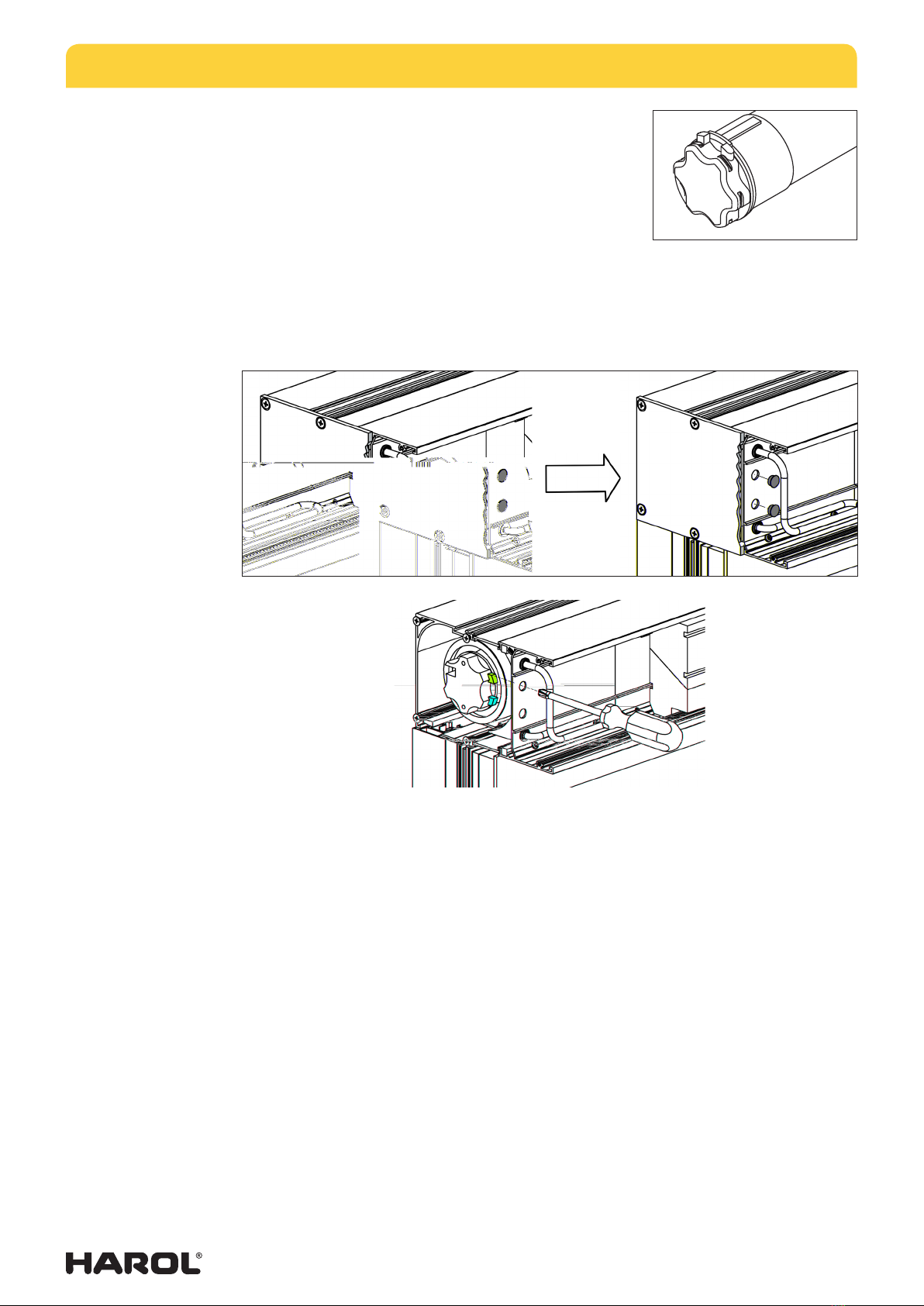
5.2. Adjusting the motor - limit switches
Temporarily connect the motor to a test cable.
On the control side of the screen, at the height of the
support plate, there is a viewing panel.
To adjust the end positions of the fabric (both top and
bottom), you can use the access holes provided in the
viewing panel. Once the plastic stops have been removed,
you can use a screwdriver to reach the motor adjusting
buttons (see Fig. 18).
If this does not have the desired result, remove the four screws to release the panel and
slide it away.
Make sure that when you replace the viewing panel, the cable does not remain in the most
front chamber. Make sure to tighten the wire.
1. Winding the motor down - Setting the bottom limit position
Let the motor wind down. Make sure that it stops at the correct point and not past the
final down position as the fabric could otherwise be rolled up in reverse and be damaged.
Themotor has not been set to any limits. Both buttons on the motor have been completely
pushed in as the factory setting (or press them both down if that is not the case). Themotor
will not stop by itself.
Let the screen wind down completely until the desired bottom position has been reached. Next
put the switch in the neutral position. Then push the white or yellow button (depending on
which side the motor is fitted), so that it rises slightly. The bottom position has now been set.
2. Running the motor up - Setting the top limit position
Now let the motor run up. Make sure that it stops in time. Just below the top limit. Nextput
the switch in the neutral position.
Then push the yellow or white button (depending on which side the motor is fitted), so
that the button rises slightly. The top position has now been set. The two limit positions
have now been set.
If it becomes necessary to reset the motor, the procedure can be repeated by simply pushing
in both buttons. By doing this the existing settings are deleted and the new settings can
be made following the instructions from point 1.
Fig. 18
INSTALLATION INSTRUCTIONS SURFACE-MOUNTED SCREEN SC900 - SC910
03/15 |19
Why use an RI2 relay box?
If several LT or LS motors are operated using the same switch, you must always use a relay
box. If relay boxes are not used, the integral limit switches will soon burn out due to the
high inductive and capacitive voltages which are mutually generated.
A useful tip: Always use the relay boxes and switches supplied by us for single operation
of 2 or more motors. The same applies to an automatic wind/sun screen.
yellow / green
brown / black
red
blue
yellow / green
blue

INSTALLATION INSTRUCTIONS SURFACE-MOUNTED SCREEN SC900 - SC910
03/15 |20
6. TROUBLESHOOTING AND REPAIRS
6.1. The screen will not roll up or down.
• The internal limit switch of the motor has not been activated in any direction. Pressboth
setting buttons and proceed with the setting of the end positions.
• Wire making poor contact when motor cable is extended. Check connections.
• Motor has overheated and runs in thermal safety mode. Leave 1/2 hour to cool down.
• Faulty adjustment of limit switches.
• No current supplied to switch. Check with a voltage meter.
• Motor is incorrectly connected. Check the connection diagram.
6.2. The motor hums.
• Check whether everything can turn freely in both directions. Is anything blocking
themotor?
• Capacitor in motor is broken (as a result of faulty connection to the motor).
• Motor is incorrectly connected, check the correct connection of the motor cables to
the switch using the diagram. A phase wire (brown or black) has been interchanged
with the neutral wire (blue). The motor will run in one direction, but in the other
direction it will just hum.
6.3. The motor does not stop in time.
• Faulty adjustment of limit switches.
6.4. Bottom lath is slanted at the top.
• The guide rails run parallel but not perpendicular to the box. First check whether
thebox is dead level, then measure along the diagonals and correct the installation.
6.5. Bottom lath drops out of the lateral guides
• Check if the end stops are fitted at the bottom of the guide rails.
6.6. The fabric tension is too slack; the bottom lath sticks or shudders when the
screen is lowered or raised.
• Check if the guide rails are aligned. The bottom lath is snug inside the guide rails.
• The zipper is not in the zipper guide profile.
• The bottom lath is not suspended properly from the fabric but rests for instance on the
window sill instead.
• The fabric is not positioned correctly in the fabric guide profile.
• Fabric is too wide.
• Lower end switch of the motor is too low or too loosely set.
6.7. Folds and waves in the fabric.
• Box and/or guide rail are not level. Position box and guide rails level.
6.8. The direction of the motor's rotation does not match the arrows on the switch.
• Swap the brown and black cable in the switch.
6.9. The fabric does not stop and roll up again.
• Use a relay box (RI2).
This manual suits for next models
1
Table of contents
Other Harol Tent manuals

Popular Tent manuals by other brands

Suncast
Suncast GS8500 owner's manual

PartySpace
PartySpace Casa Africa SAVANNA LODGE RONDE... manual

Oxybul
Oxybul 303334 quick start guide

Creative Play
Creative Play OCTAVIA OS117 installation instructions

Campvalley
Campvalley WMT-1010A Setup instructions

Rocktrail
Rocktrail POP-UP TENT 2.1 Operation and safety notes


