Canadian Tire 37-1398-2 User manual

- 1 -
AUTO STORAGE SHELTER
INSTRUCTION MANUAL
37-1398-2
10' x 17' x 9' 6" (3 x 5.2 x 2.9 m) 8-Leg
Questions?
If you have a question or if there are missing parts, please call:
1-866-567-4089
Monday-Saturday 7:00 a.m.-8:00 p.m. EST
Please read instructions fully before beginning assembly.
V.4.

- 2 -
TABLE OF CONTENTS
SAFETY INSTRUCTIONS...................................... 3
PARTS LIST............................................................4
ASSEMBLY........................................................4-12
LIMITED WARRANTY...........................................13

- 3 -
SAFETY INSTRUCTIONS
READ THIS PAGE FIRST!
! WARNING!
1. The cover is made of 3-layer polyethylene. Please do not use open flames and heated elements inside
or in close proximity to the product (including all types of stoves, gas heaters, gas lanterns, citronella
torches, mosquito coils, etc). The fabric will burn if left in continuous contact with a flame source. Any
burns as a result of using open flames or heating elements voids the manufacturer's warranty.
2. This is a temporary structure and is not recommended as a permanent structure.
3. Choose your shelter’s location carefully. Check for overhead utility lines, branches, etc. Do NOT install
near roofs or other structures that may shed snow or ice onto shelter.
4. Take an inventory of all parts before attempting installation.
5. Always wear safety glasses when assembling this product. Wear gloves when working with tubing, to
prevent cuts or abrasions.
6. Install product on a level surface.
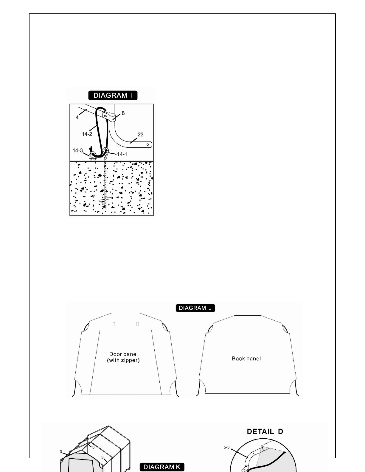
7. Anchors must be used with all shelters. When erecting shelters, covers should NOT be installed on
any product until it has been properly anchored to the ground. Any shelter that is not anchored
securely or properly will blow away. Proper anchoring for the shelter and the specific conditions are the
responsibility of the customer.
8. NEVER start engines from any vehicles or machines within the closed shelter. Special ventilation or an
open door should be used at all times for these situations.Any work with paints, cleaning products, etc.,
may require additional ventilation.
9. Do NOT use barbeque grills, smokers or other flammable equipment under or inside any shelters.
10. Do not cook, smoke, use flammable devices, refuel, store flammable materials or operate gas
powered vehicles/equipment in this shelter. Keep open flames a safe distance away from the shelter.
11. No snow accumulation should be allowed on the shelter. Watch out for accumulated snow on the roof.
Snow or ice accumulation may cause your shelter to collapse. This shelter is NOT meant to hold heavy
snow or ice loads. Brush snow and ice off the roof top with a broom or mop. Failure to remove snow
will void the manufacturer's warranty.
12. Never clear the roof of snow or debris from inside the shelter due to risk of collapse, damage to
property, personal injury and/or death.
13. Municipal by-laws must be checked prior to setting up the portable garage.
CARE & CLEANING
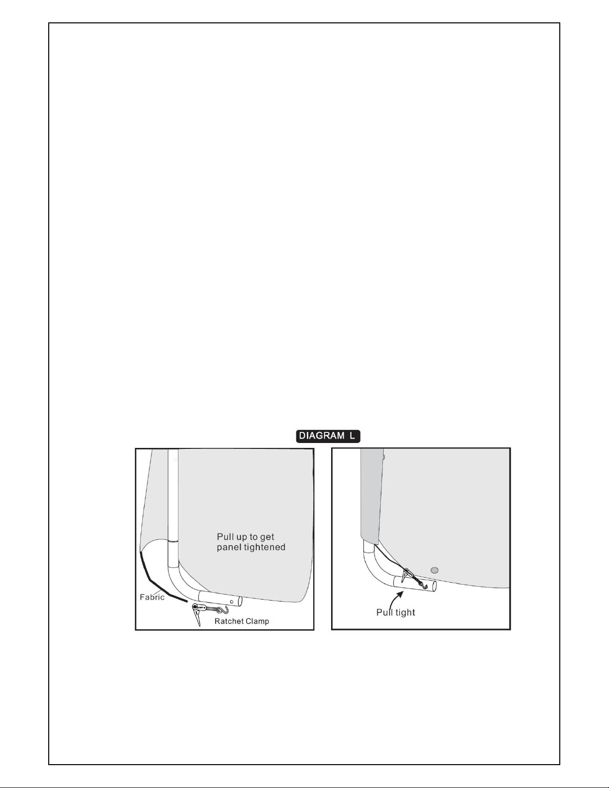
1. Periodically check the anchors, the tension of the ropes and all hardware to ensure the stability of the
shelter during the first few weeks of use and periodically thereafter. It may be necessary to tighten the
cover and the ends a few times. Be sure that all covers and ends are kept tight.
2. Do NOT apply any polishing or protective products to the cover and ends or use harsh abrasives,
bleach or cleansers. Cover and walls can be easily cleaned with mild soap and water.
3. Do not use the product in environments for which it is not intended (e. g.: extreme cold, high winds,
extreme heat, heavy rainfall, etc).
Please note that we are not responsible for damages to or caused by the shelter .

- 4 -
ASSEMBLY
Please read instructions fully before beginning assembly.
Note: It is suggested that you have at least one person help you during assembly as some
of the steps require heavy lifting.
Step 1:
Unpack and check the contents of the box. Make sure that you have all the parts described
in the below parts list.
If parts are missing, please contact the Toll-free Helpline:
1-866-567-4089
PARTSLIS

- 5 -
FRAME ASSEMBLY OVERVIEW
Tools (not included with the shelter) required to assemble shelter:
1-Slot screwdriver
1-Rubber mallet (to be used to ensure all pipes are fully inserted).

- 6 -
Step 2:
Lay out all the roof assembly parts as shown in Diagram B.
Note:
Detail C shows the directions of
each connector in use.
After being installed, the welded
socket for cross rail must be below
the bend.
Step 3: Roof Peak Assembly
Note: It is suggested that you have at least one person help you from this point forward during
assembly as some of the steps require heavy lifting.
A. Following below Diagram C, assemble the centre section of the roof first by using Cross Rails

- 7 -
(#3), 3-Way Top Connectors (#5-1) and 4-Way Top Connectors (#6-1). Then complete one side
by inserting Rafter Poles (#2) into the Connectors (#5-1 & #6-1), then repeat procedure for the
opposite side.
Be sure that all pipes insert fully together. Use a rubber mallet or wood dowel when
necessary.
B. As shown below Diagram D, complete the roof assembly by inserting 3-Way Connectors
(#5-2 -3) and 4-Way Side Connectors (#6-2) to each side; insert Cross Rail (#3) to
complete step.
Step 4: Attaching Upright Pole Support
Note: This assembly has no bolted connection. An assistant is necessary to complete the assemblyas
some of the steps require heavy lifting.
A.Prepare the 4 pieces of Centre Uprights (#1-1) by inserting a foot plate
into each Upright. To affix each foot plate use Pin (#15) and Cotter Pin
(#16) per upright. Place foot plate onto upright bottom end with punched
holes. Align upright holes with those of foot plate and insert Pin (#15).
Push pin through all holes until hole in pin end is exposed. Secure pin into
position by inserting Cotter Pin (#16) and then spreading tongues of
Cotter Pin (#16) with a slot screwdriver. Repeat for all 4 upright poles.See
Diagram E.
B.Connect Corner Upright (#1-2) to Bent Corner Leg (#23). Use a rubber
mallet when necessary. See DiagramF.
C. While one person raises one side of the roof assembly (ensure the opposite side
remains resting on the ground) the other person inserts Centre Uprights assembly (#1-1)
and Corner Uprights assembly (#1-2). Do not let the roof assembly rest on the upright
poles until a set of four (#1-1 & #1-2) have been installed completely to one side. See

- 8 -
Diagram G.
D. Repeat step C above for the other side of the structure. See Diagram H.
Step 5: Anchor Shelter
Note: Make sure the 8 legs are square before anchoring.
Base Fastening Stakes (#23) must be used to anchor the shelter. Four fastening stakes are
provided with the shelter. They are to be located on the 3-Way Connector at each corner of

- 9 -
the shelter.
Using a small length pipe or a wooden dowel insert it through the eye of the fastening
stake.Applying downward pressure and using the pipe or dowel for leverage, twist the
fastening stake into the ground until only 3”(7.62 cm) of the stake remains above ground
surface. Using the wire provided lash the Cross Rail (Bottom) (#4) down to the fastening
stake as shown in the illustration.
THIS SHELTER MUST BE ANCHORED AND IS NOT
TO BE USED WITHOUT COMPLETING THIS STEP.
DEPENDING ON SOIL CONDITIONS, THE
ANCHORS PROVIDED MAY NOT BE
SUFFICIENT TO HOLD THE STRUCTURE DOWN
DURING TIMES OF HIGH WINDS. THE USER OF
THE SHELTER MUST ENSURE TO TAKE
ADEQUATE PRECAUTIONS TO ANCHOR THE
SHELTER SECURELY.
Note: Do not proceed on to the panel and covering
steps until the frame is properly anchored
Step 6: Attaching End Panels
Starting from the peak, remove the Cross Rail (#3) from the 3-Way Top Connector
(#5-1). Place exposed at the top of the panel over the 3-Way Connector and under the
cross pole as shown in Detail E on the next page. Replace the Cross Rail (#3). At each
corner remove the Cross Rail (#3) and pull the fabric around to the inside, placing the
3-Way Socket (#5-2 or #5-3) through the opening in the fabric as shown in Detail D. Tighten
the panel by following Diagram L. Repeat above for another door.
See Diagram J for tightened end panel.

- 10 -
RATCHET ASSEMBLY INSTRUCTION
TIGHTENING
Open the Ratchet as shown in the picture below and pass the end of the strapping through
the slot of the ratchet spool; pull excess strapping through spool. Then pump ratchet handle

- 11 -
repeatedly to draw strapping tight (Caution: excessive tightening can cause damage to
straps and/or anchor point). Tighten ratchet to make final adjustments to cover.
Tighten ratchet to make final adjustments.
The shelter is now ready for use.
Note: Please check periodically and tighten the Ratchet Tie Down as needed. Monthly
inspection recommended.
When disassembling the shelter, depress the spring-loaded bar and open ratchet handle
completely to get the strapping out.
PLEASE RE-READ ALL WARNINGS CONTAINED ON PAGE 3 OF THESE
INSTRUCTIONS. SAVE THESE INSTRUCTIONS FOR FUTURE USE.
To dismantle, execute all instructions in reverse order.
Store your shelter in a cool, dry location
between seasons to prolong usable life of all
components. Components are not equally
durable and will require replacement over
time at differing intervals.

- 12 -
The left picture shows what it
looks like after the end panel
is tightened.
Step 7: Installing Roof Tarp and Lower Cross Rails
Note: Please fix the ratchet before installing Roof Tarp.
Using the Ropes (#21) for roof tarp assembly.
Lay out the Roof Tarp (#18), makeing sure the pockets with black straps should be
positioned so they will be located at the shelter front and back ends when assembly is
completed. Locate the open, empty pockets running perpendicular to the strap pockets
and near two edges of the roof tarp. When the roof tarp is in position these empty
pockets should be aligned facing the interior of the shelter along the lower frame of both
long sides.
Tie the two Ropes (#15) to the roof tarp through the eyelets on two corners. Throw
the rope over the frame to the other side. Go to the other side and pull the rope to get the
roof cover onto the frame. Draw the tarp gently over the frame ensuring that it does not
snag.
Requires two people.
Once the roof tarp is draped over the frame check the overhang of the roof tarp at both

- 13 -
the back and door panel. Ensure the overhang is approximately equal at each of the ends. If
it needs to be adjusted both people pulling together from the same end of the structure to
adjust the estimated amount simultaneously or the roof tarp may become twisted.
Once satisfied with the placement insert the remaining Cross Rail (#4) through the
interior pockets of the roof tarp.
Both people working together will push down on the cross rail but on opposite sides of
the same end of the frame. Estimating approximately the same height to each side for the
cross rail ,loosely secure one cross rail in place first using 3-Way Cover Rail Clamp (#8) for
the end frame along with 1- piece each of M6X45 Bolt (#11), M6 Nut (#12) and M6 Washer
(#13). See Detail F.
Repeat ,securing the opposite end of the cross rail using a 4-Way Rail Clamp (#11) and
the same hardware. See Detail B.
Only finger tighten the bolts and nuts at this time. Complete installing all cross rails in
this manner.
Once satisfied with the height position of all cross rails across both sides tighten the
nuts and bolts along one side of the frame. After tightening, the two people working together
will tighten the cross rails to the opposite side of the shelter. One will push down on the
cross rail causing the roof tarp to become taut while the other tights the bolt and nut.
When the cover rails are all secured proceed to the 4 corners straps and tighten them
fully to the feet through the ratchet.

- 14 -
LIMITED WARRANTY
This product is guaranteed for 1 year from the date of original retail purchase
against defects in materials and workmanship.
Subject to the conditions and limitations described below, this product, if returned to us
with proof of purchase within the stated warranty period and if covered under this
warranty, will be repaired or replaced (with the same model or one of equal value or
specification), at our option. We will bear the cost of any repair or replacement and any
costs of labour relating thereto.
These warranties are subject to the following conditions and limitations:
a) A bill of sale verifying the purchase and purchase date must be provided;
b) This warranty will not apply to any product or part thereof which is worn or broken or
which has become inoperative due to abuse, misuse, accidental damage, neglect or
lack of proper installation, operation or maintenance (as outlined in the applicable
owner’s manual or operating instructions) or which is being used for industrial,
professional, commercial or rental purposes;
c) This warranty will not apply to normal wear and tear or to expendable parts or
accessories that may be supplied with the product which are expected to become
inoperative or unusable after a reasonable period of use;
d) This warranty will not apply to routine maintenance and consumable items such as,
but not limited to, fuel, lubricants, vacuum bags, blades, belts, sandpaper, bits, fluids,
tune-ups or adjustments;
e) This warranty will not apply where damage is caused by repairs made or attempted
by others (i.e. persons not authorized by the manufacturer);
f) This warranty will not apply to any product that was sold to the original purchaser as
a reconditioned or refurbished product (unless otherwise specified in writing);
g) This warranty will not apply to any product or part thereof if any part from another
manufacturer is installed therein or any repairs or alterations have been made or
attempted by unauthorized persons;
h) This warranty will not apply to normal deterioration of the exterior finish, such as,
but not limited to, scratches, dents, paint chips, or to any corrosion or discolouring
by heat, or abrasive and chemical cleaners;
i) This warranty will not apply to component parts sold by and identified as the product
of another company, which shall be covered under the product manufacturer’s
warranty, if any.
Additional Limitations
This warranty applies only to the original purchaser and may not be transferred.
Neither the retailer nor the manufacturer shall be liable for any other expense, loss or
damage, including, without limitation, any indirect, incidental, consequential or
exemplary damages arising in connection with the sale, use or inability to use this
product.
Notice to Consumer
This warranty gives you specific legal rights, and you may have other rights, which may
vary from province to province. The provisions contained in this warranty are not
intended to limit, modify, take away from, disclaim or exclude any statutory warranties
set forth in any applicable provincial or federal legislation.
Table of contents