Harpers NL-404 User manual

cr
r=
tslco
-l l-
et 1*l
LVi'
rf
o
tart
d,j
r,
L3
4a
{st
Et
-
3
9-
Fl
-!
,EF]l
rv
$ tr
o
s
GENERAL INFORMATION
The Harpers Model NL-404 is a two-speed tape recorder designed to play and record
two tracks of material on standard-width recording tape.
Recordings can be made from a phonograph, radio, television receiver, or directly
from the microphone.
The two speeds arc? L/2 and 3 3/4 ips. Using both tracks, the recording times are
as follows:
ReeI Size
5" (600 ft. )
HOWARD W. SAilS &
The listing of any available replacement part herein does
not constitute in any case a recommendatlon, warranty or
guarantyby Howard W. Sams & Co., Inc., as to the quality
and suitability of such replacement part. The numbers of
these parts have been compiled from lnformatlon furnlehed
to Hovard W. Sams & Co. , Inc. , by the manufacturers of
cQ498
7 r/2 ips
/2 hour
(G |o.r I I{ (C. lndlanapollB 6, lndlana
the particular type of replacement part listed. Repro-
duction or use, without exprees permission, of editorial or
pictorial content, in any manner, le prohibited. No patent
Itability is assumed wlth reepect to the uae of the lnforma-
tion contained herein. @ ISOZ Howard W. Sams & Co. , Inc. ,
3 3/4 ips
I hour
Model NL-404 is designed to operate on 60 cycles, Il0-120 volts, AC supply only.
Supplied By:
Harpers lnternational, lnc.
3 l5 Fifth Avenue
New York I.6, New York
q
Fll
-l
ct!)
€
G'
-l
e
-
et
t+l
-
CE)
Indianapolis 6, Indiana.
otTt 10 - 62
Printed in U.S. of Amerlca
sH 600 r0[DER I
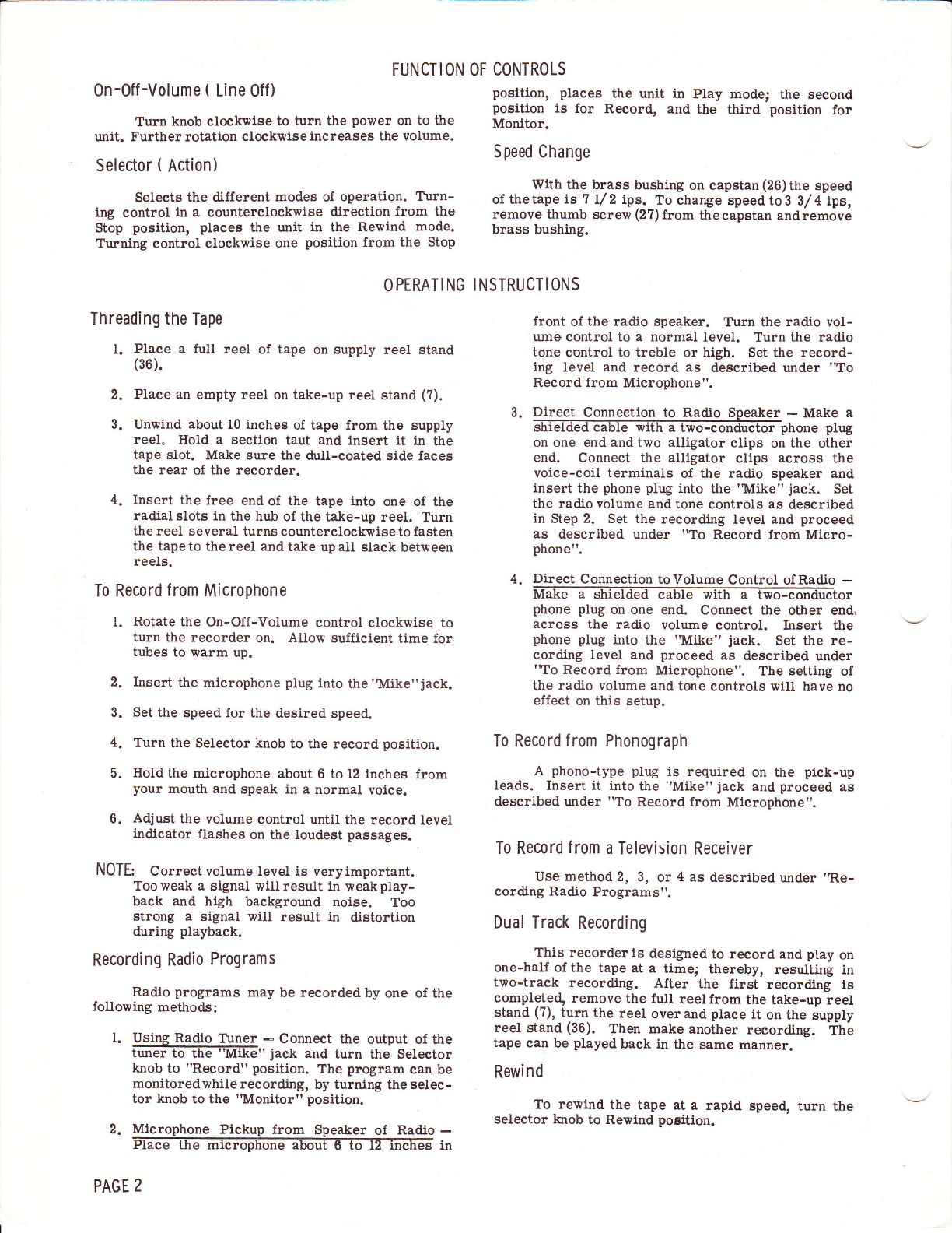
FUNCTION OF CONTROLS
0n-Off -Volume ( Line Off )
Turn knob clockwise to turn the power on to the
unit. Further rotation clockwise increases the volume.
Selector ( Action)
Selects the different modes of operation. Turn-
ing control in a counterclockwise direction from the
Stop position, places the unit in the Rewind mode.
Turning control clockwise one position from the Stop
O PERAT I NG
Threading the Tape
l. Place a full reel of tape on supply reel stand
(36).
2. Place an empty reel on take-up reel stand (?).
3. Unwind about I0 inches of tape from the supply
reel" HoId a section taut and insert it in the
tape slot. Make sure the dull-coated side faees
the rear of the recorder.
4. Insert the free end of the tape into one of the
radial slots in the hub ol the take-up reel. Turn
the reel s everal turns counterelockwise to fasten
the tapeto thereel and take upall stack between
reels.
To Record f rom Microphone
l. Rotate the On-Off-Volume control clockwise to
turn the recorder on. Allow sulficient time for
tubes to warm up.
2. Insert the microphone plug into the'Mike"jack.
3. Set the speed for the desired speed.
4. Turn the Selector knob to the record position.
5. Hold the microphone about 6 to 12 inches from
your mouth and speak in a normal voice.
6. Adjust the volume control until the record level
indicator flashes on the loudest passages.
N0TE: Correct volume level is veryimportant.
Tooweak a signal willresult in weakplay-
back and high background noise. Too
strong a signal will result in distortion
during playback.
Recording Radio Programs
Radio programs may be recorded by one of the
following methods:
I. Using Radio T\rner - Connect the output of t}re
iunFT6-Tfr€TiiE?.' jack and turn the Selector
knob to "Record" position. The program can be
monitoredwhile recording, by turning the selec-
tor knob to the 'Monitor" posltion.
2. Microphone Pickup from Speaker of Radio -
in
PAGE 2
position, places the unit in Play
position is for Record, and the
Monitor.
mode; the second
third position for
Speed Change
With the brass bushing on capstan (26)the speed
of thetape Ls 7 L/ 2 ipg. To change speed to 3 3/4 ips,
remove thumb screw (27)from thecapstan andremove
brass bushing.
I NSTRUCTI ONS
front of the radio speaker. Turn the radio vol-
ume control to a normal level. Turn the radio
tone control to treble or high. Set the record-
ing level and record as described under 'To
Record lrom Microphone".
3. Direct Connectlon to Radio Speaker - Make a
hone plug
on one end and tno alligator clips on the other
end. Connect the alligator clips across the
voice-coil terminals of the radio speaker and
insert the phone plug into the 'Mike" jack. Set
the radio volume and tone controls as described
in Step 2. Set the recording level and proceed
as described under "To Record from Micro-
phone".
4. Direct Connection toVolume Control of Radio -
Make a shielded cable with a two-conductor
phone plug on one end. Connect the other end,
across the radio volume control. Insert the
phone plug into the 'Mike" jack. Set the re-
cording level and proceed as described under
"To Record from Microphone". The setting of
the radio volume and tone controls will have no
effect on this setup.
To Record from Phonograph
A phono-type plug is required on the pick-up
Ieads. Insert it into tle 'Mike" jack and proceed as
described under "To Record from Microphone".
To Record f rom a Television Receiver
Use method 2, 3, or 4 as described under ,R,e-
cording Radio Programs".
Dual Track Recording
This recorder is designed to record and play on
one-half of the tape at a timel thereby, resulting in
two-track recordlng. After the first recording is
completed, remove the full reelfrom the take-up reel
stand (?), iurn the reel over and place it on the supply
reel stand (36). Then make another recording. Thb
tape can be played back in t}re same manner.
Rewind
To rewind the tape at a rapid speed, turn the
selector knob to Rewind poEition.
=
o
9T
llt>
FF
r.lI
3n
lv
j\ta
o
s
HAN I
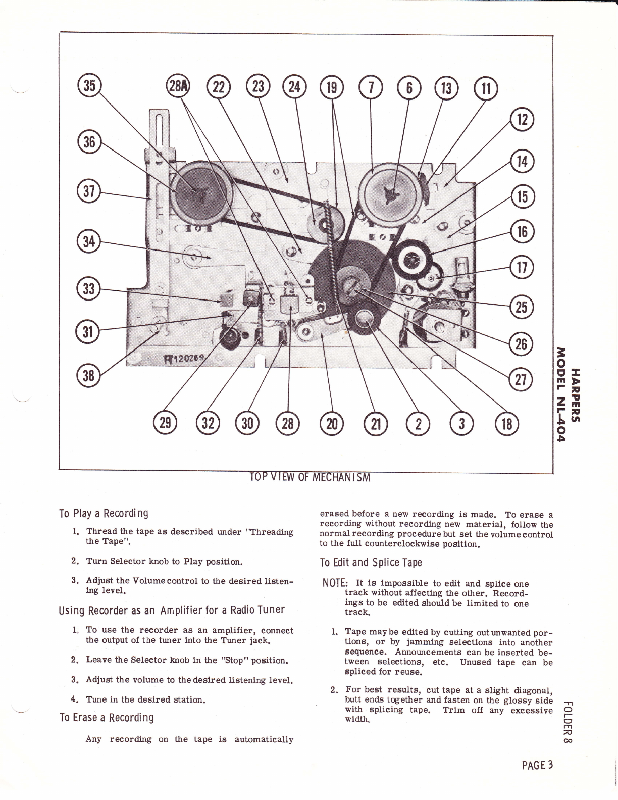
To Play a Recording
t. Thread the tape as described under "Threading
the Tape".
2. Turn Selector knob to Play position.
3. Adjust the Volume control to the desired listen-
ing level.
Using Recorder as an Amplif ier for a Radio Tuner
l" To use the recorder as an amplifier, connect
the output of the tuner into the Tuner jack"
2. Leave the Selector knob in the "Stop" position.
3. Adjust the volume to the desired listening level.
4. Ttrne in the desired station.
To Erase a Recording
erased before a new recording is made. To erase a
recording without recording new materlal, follow the
normal recording procedure but set the volume control
to the full counterclockwise position.
To Edit and Splice Tape
NOTE: It is impossible to edit and splice one
track without affecting the other. Record-
ings to be edited shoutd be Iimited to one
track.
l. Tape maybe edited by cutting outunwanted por-
tions, or by jamming selections into another
sequence. Announcements can be inserted be-
tween selections, etc. Unused tape can be
spliced for reuse.
2. For best results, cut tape at a slight diagonal,
butt ends together and fasten on the glossy side
with splicing tape. Trim off any excessive
width. O
I
rn
7
@
Any recording on the tape is automatically
PAGE 3
DISASSEMBLY
To Remove Mechanism f rom the Case 4. Remove the ftve hex nuts hotding mechantgm tn
the case.
l. Remove the Selector and On-Off-Volume control
knobs. 5. Lift mechanism up and unsolder the speaker
leads.
2. Remove thumb serew from the pressure roller
and remove presgure roller. 6. Lift the mechanism from the case.
3. Remove the four thumb screrils from t}te top 7. To reassemble, reverse the foregoing proced-
plate and remove top plate. ure.
ADJUSTMENTS
ReCOfd-PlaybaCk Head B. Set Votume control to the center of its range.
1. Thread a prerecorded 5r000-cycle note tape 4. Adiust serews(28A)for theangular position 6rat
onto t}te recorder. wlll give maximum output.
2. Place the recorder in the Playback mode.
CLEAN I NG
The record head, erase head, capstan, pres- and alcohol to remove the residue.
sure roller, and tape guides should be cleaned occa-
sionally to remove the tape resldue which ls worn off Clean the rubber-tlred idler wheels and belts
the tape as it passes these parts. Use a soft cloth with cleaning fluid.
LUBRICATION
All rotating parts areprovided with oilite bear- tlme. When lubrication becomes necessary, apply a
lngs and are lubricated at the factory. Under normal thin film of oil on bearing surfaces.
use, no lubrication is required for a long period of
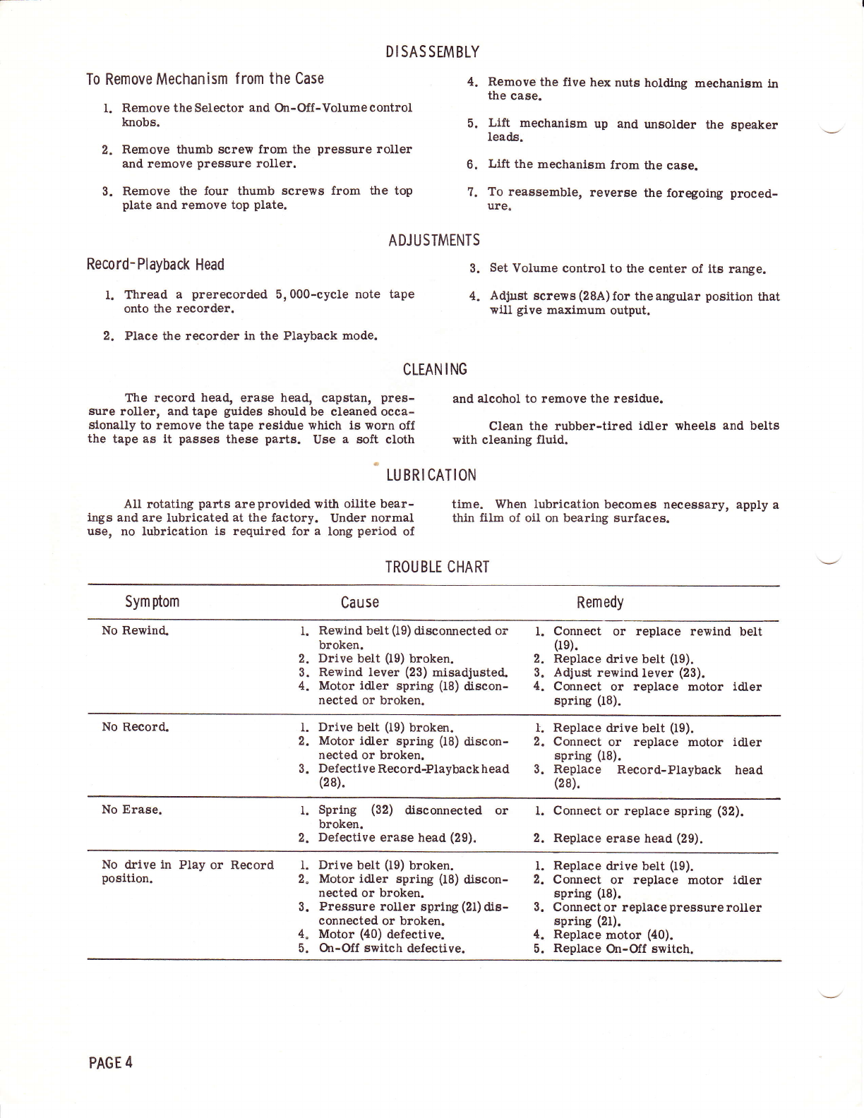
TROUBLE CHART
Sym ptom Cause Remedy
No Rewind. l. Rewind belt (19) diseonnected or l. Connect or replace rewind belt
broken.
2. Drive belt (19) broken. 0e).
2. Replace drive belt (19).
3. Rewind lever (23) misadjusted- 3. Adjust rewind lever (23).
4. Motor idler spring (I8) discon- 4. Connect or replace motor idler
nected or broken. spring (18).
No Record. I. Drive belt (19) broken. l. Replace drive belt (19).
2. Motor idler spring (18) discon- 2. Connect or replace motor idler
nected or broken. spring (18).
3. DefectiveRecord-Playbackhead 3. Replace Record-Playback head
(28). (2s).
No Erase. l. Spring (32) disconnected or l. Connect or replace spring (32).
broken.
2. Defective erase head (29). 2. Replace erase head (29).
No drive in Play or Record 1. Drive belt 09) broken.
position.
connected or broken.
4. Motor (40) defective.
l. Replace drive belt (r9).
2" Motor idler spring (18) discon- 2. Connect or replace motor idler
nected or broken. spring (18).
3. Pressure roller spring(21)dis- 3. Connector replacepressureroller
spring (21).
4. Replace motor (40).
PAGE 4
5. On-Off switch defective. 5. Replace On-Off switch.

BOTTOM VIEW OF AMPLIFIIR
35W4
I2AU6
I2AV6
=
o
E'tr
Ff
2E
f-
.Lu
o
5
'.l.l
o
t-
q7
ln
7
6
PAGE 5
Ref.
No. Part
No. Description
I
2
3
4
5
6
7
I
I
l0
tl
L2
l3
t4
l5
16
L7
18
19*
20
2L
537
539
505
502
536
531
561
533
534
54r
5r7
549
5u
509
538
548
547*
5t9
550
Escutcheon Thumb Screw (4 Req'd.)
Pressure Roller Thumb Screw
Pressure Roller
Knob, On-Off-Volume
Top Plate
Thumb Screw
Reel Stand, Take-up
Felt Ring, Take-up Reel Stand
Friction Wheel
Sleeve, Friction Wheel
Shoe, Brake
Lever, Brake
Spring, Brake Lever
Lever, Motor Idler
Main Actuating Lever
Idler Wheel
Motor Pulley
Spring, Motor ldler Lever
Belt, Drive, Rewind (2 Req'd. )
Pressure Roller Lever
Spring, Pressure Roller Lever
I Be. Drive- Rewind^ WALSCO Part No- l4?4
d,
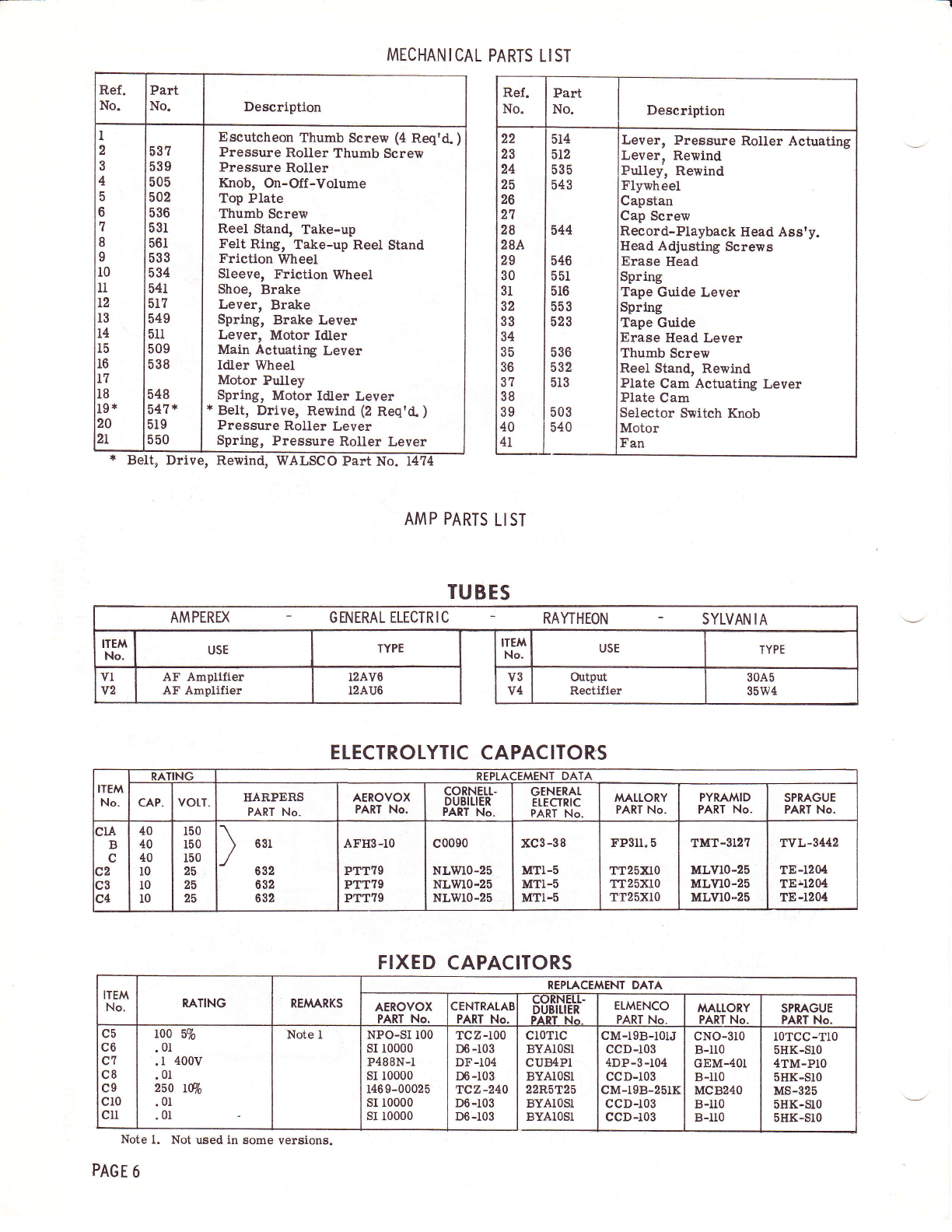
MECHANICAL PARTS LIST
AMP PARTS LIST
Ref.
No. Part
No. Description
22
23
24
25
26
27
28
28A
29
30
3t
32
33
34
35
36
37
38
39
40
4T
5r4
5r2
535
543
544
536
532
5r3
546
551
516
553
523
503
540
Lever, Pressure Rotler Actuating
Lever, Rewind
Pulley, Rewind
Flywheel
Capstan
Cap Screw
Record-Playback Head Ass'y.
Head Adjusting Screws
Erase Head
Spring
Tape Guide Lever
Spring
Tape Guide
Erase Head Lever
Thumb Screw
Reel Stand, Rewind
Plate Cam Actuating Lever
Plate Cam
Selector Switch Knob
Motor
Fan
TUBES
AMPEREX - GENERAL ELECTRIC - RAYTHEON - SYLVAN IA
AF Ampllfier
AF Amplifier
ELECTROTYTIC CAPACITORS
ITEM
No.
RATING REPLACEMENT DATA
CAP. VOTT. HAR,PERS
PART No. AEROVOX
PART No. coRNErt-
DUBITIER
PART No.
GENERAL
EtECTRIC
PART No. MALLORY
PdRT No. PYRAMID
PART No. SPRAGUE
PART No.
3rA
B
c
c4
40
40
40
t0
l0
IO
150
r50
t50
25
25
25
) oer
632
632
632
AFHS-TO
PTT79
PTT?9
PTT?9
c0090
NLmo-25
NLmo-25
NLWIo-25
xc3-38
MTI-5
MTI-5
MTI-5
FP3ll.5
TT25Xr0
TT25Xl0
TT25Xl0
TMT-3T2?
MLV10-25
MLVr0-25
MLVr0-25
TVL-3442
TE-1204
TErl204
TE-1204
FIXED CAPACITORS
c5
c6
c7
c8
c9
cl0
clr
100 570
.01
.r 400v
.01
260 tw
.01
.01
NPO-SI 100
sr 10000
P488N-l
sI 10000
146 9-00025
sI 10000
sI 10000
TCZ-100
D6 -103
DF-104
D6 -103
TCZ-240
D6-r03
D6-r03
cM-l9B-rolJ
ccD-103
4DP-3-104
ccD-103
cM-l9B-251K
ccD-103
ccD-r03
cloTlc
BYAIOSl
CUEIPI
BYA1OSI
22R5T25
BYAIOSI
BYAIOST
Note l. Not used in some versions.
PAGE 6
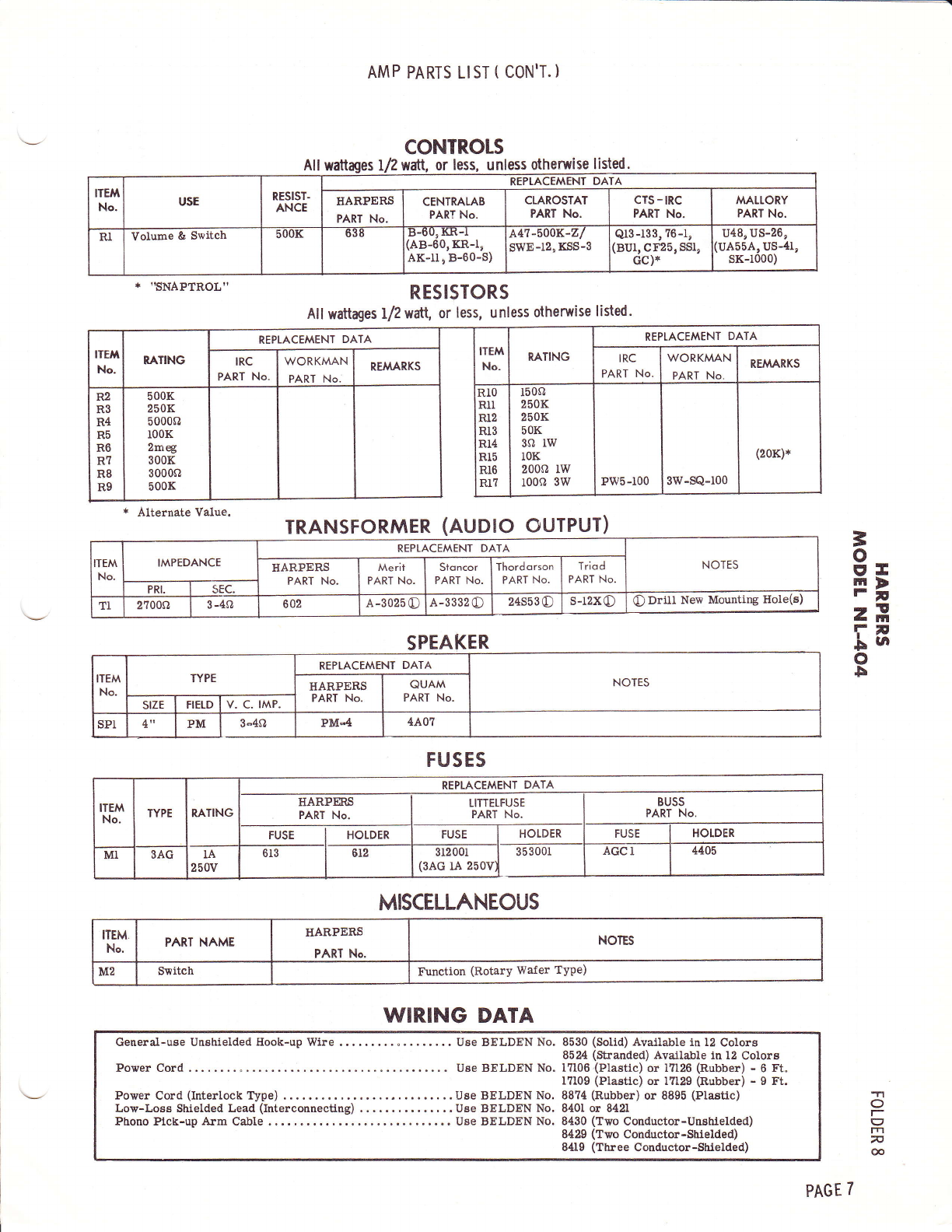
CONTROLS
All wattages I/2watl, or less, unless otherwise listed.
ITEM
No. usE RESIST.
ANCE
REPTACEMENT DATA
HARPERS
PART No. CENTRALAB
PART No. CTAROSTAT
PA,RT No. cTs - tRc
PART No. M^ALLORY
PART No.
RI Volume & Switch b00K 638 tt-ou, nr-l
:AB-60,KR-1,
AK-11 ! B-60-S)
A47-'OOK-Z/
swE-12, KSS-3 Qt3-133,76-1,
(8U1, CF25, SSl,
Gc;*
u48, u5-26,
luA55A, US-41,
sK-1000)
* ''SNAPTROL''
* Alternate Value.
AM P PARTS LIST ( CON'T. )
RESISTORS
All wattages L/2wdtl, or less, unless otherwise listed.
TRANSFORMER (AUDIO OUTPUT)
SPEAKER
=
o
ET
FI
r!
3n
r-
$ta
o
b
-1
O
t-
g
lrl
n
6
REPLACEMENT DATA
REPLACEMENT DATA
WORKMAN
PART No.
R2
R3
R4
R5
R6
R7
R8
R9
TEM
No. IMPEDANCE REPLACEMENT DATA NOTES
HARPERS
PART No. Merit
PART No. Stoncor
PART No. Thordorson
PART No. Triod
PART No.
PRI. sEc.
TI 2700s, 3-4sl 602 A-3025 c) A-3332 c) 24s53€) s-r2xc) O Driil New Mounting Hole(s)
ITEM
No. TYPE REPLACEMENT DATA
NOTES
HARPERS
PART No. QUAM
PART No.
srzE FIETD v- c- tMP.
sPl 4" PM 3-4s, PM-4 4A0?
FUSES
ITEM
No. TYPE RATING
REPLACEMENT DATA
TIARPM,S
PART No. LITTETFUSE
PART No. BUSS
PART No.
FUSE HOLDER FUSE HOLDER FUSE HOTDER
MI 3AG rA
250V 6r3 6r2 3r200r I 35300r
(3AG rA 25ovt AGCI 4405
MISCELLANEOUS
ITEM
No. PARI NAME IIARPERS
PART No. NOTES
M2 S$itch Function (Rotary Wafer TYPe)
WIRING DATA
General-use Unshielded llook-up Wire .. .. Use BELDEN No. 8530 (Solid) Avatlable in 12 Colorg
8524 (Stranded) Available in 12 Colore
Pover Cord ..... . Use BELDEN No. 17106 (Plastic) or l?126 (Rubber) - 6 Ft"
17109 (Plastic) or 17129 (Rubber) - 9 Ft.
Power Cord (Interlock Type) .. ....Use BELDEN No. 88?4 (Rubber) or 8895 (Plastic)
Low-Loss Shielded Lead (InterconnecHng) . Uee BELDEN No, 8401 or 8421
Phono Pick-up Arm Cable . Use BELDEN No. 8430 (Two Conductor-Unshielded)
8429 (Two Conductor-Shielded)
8ttl9 (Three Conductor-Shielded)
PAGE 7

,I
rf
o
lns
e,j
lll rr
L3
4t
{u
.t-
b
Ee 3€a-E F
EE s EFEe! :s
F' $lE;;uge9:
I*E=EgiEgEil
:: E g E sE: - E z'
;:ga€EEEEEiJ
li;;sEgEE: F
e3
L,
N<
F>
@3
x3
@3
U
;s
@,
Hd
GI
F
E,
I
VI
=
e.
FU.
r-r Q
o-E
+<E
IJ
fE- @=
o
<l
co
E@
6i
.J
ii r-d
=23
4^
RHH
5--
z-= (J
OL=
z 1-,J
ffP
LF
;<H
c, ii
;gr
rrJ !
HE
=t
e.
trJ F
=a
oz
Lrt R
Lr't v
lrl UJ
JI
ZF
==
ag
F(.5
2. z.
d.1 o
(J
-> r .:Y
#s=E
- 6-E! Vd
3-or.-<
z.*. z>
lJJv--l
v/ (-) O- -l
JU
i-_o.E=
E2Ez
4
rrr6oo
FHHS
d==G
=./, tlt ,^
o<<a
gs=E
J
J
{I+-*
lrJ
(-)
e,
o
tlt
-*
6=E
;96
&.
o
a\
rE=
==R
a r-n tLl
V,
o
t\
NI rz F
o
v
o
6.'
.F-
o
o
(\I
+-
c
o.
t\
o
\z
o
GJ v
o
o
rr1
o.
t\
d
c
6J c
<t
c! r<l
C\I
c
o.
t\
c
oc
6J s
Lt\
c
tI\
v
rn lz
(l\
Y,
o
o
rn (-)
z.
c
c
too
Lr\ o-
F
l!
4
F
\o
C\I
\o
\I
d
r3\
o
(Y\
sl
=
rn
=
trj
FC\.1 g
o
lrl
CJ
&,
=
o
tt
tf)
\f
=3
H|.)
-(It
e
a
(9
z.
a
s
&
I!
(J
z
rll', E
I .Jt
IH
r=al-
\!.i/ T "
h
o tz.
z>o
<o^
2e3
i.&t O O
\Z lr-
sPu
o6t
n; S--'
\2rOU
?:
=n.tl
*=vt
EPH
cr(J-
-I4JO
aE=
L/i -r g
-6=
o{o
c)Lz
oo(
a st2
=t=
C9 lrl
- at1 <)
.n e, <,
?Hd
!36cr-:
Err L-
!!a 2z
===i
=gHE
=,
o
e
lJ-
c)
Lr-l
C/'
N,
E=
T, Z. Lli
c)- c)
F= =
=u 5
a= g e,
z==82 3P
(J (J--a-!r^-
E=*EE-;3H=
5-oE
t! tz.l cL (, H G.l (Y..' <l tn
oo
i@H @
c
o
rn
>z
o
@
I
I
I
I
I
I
I
I
I
al
LrJ e-
+l
*l
Or
qi
oi
c):
lrJ I
u, l
i!
5i
o-l
5@
@
z.
O
E
c\t _
EI
lJl
ct) '
A
€/
\Z
o
o
tn
@
Ee
rJ\
. I4J
lr, 6t
o-*S
O*
g\
<.: d
=2.
<-
E
E
O
o
rd
@
o-€
=?
=o{
6
@
o
oo
&.
IJ
AE
(=) r
v L.J
IJ-J
ct)
v.
(J
F
J
o-
z
&.
L!,1
z.
F
PAGE 8


