Crestwood CP-201 User manual

PHoToFAcr- FolJ"* CRESTWOOD
moDEt cP-201
oo
oq
Od.
}Y
hE
6g
3*
Hq
rq
;{
po
leO
9e
Figure 1
GENERAL INFORMATION
The Crestwood Tape Recorder, Model CP-201, is designed to magnetically record
on a standard ?-inch reel of" lf{" wide tape, two tracks instead of one, which
doubles the playing time with no loss in frequency response or quality.
Erasing, in the Model CP-201, is obtained by a 35 KC frequency at approximately
1?5 volts through the erase head coil. The erase head is so placed on the recorder
that the tape passes through it before the recording head. Erasure takes place
automatically as recording occurs, so that no special step is necessary.
Power supply is from 105-120 volts, 60 cyclesAC. Do not connect the unit to
DC power source.
Manufactured by:
Crestwood Recorder Corporation
218 South Wabash Avenue
Chicago 4, Illinois
Fhis molerial compiled and published by
& co., lNc., INDIANAPO
0ut t2_50
o ALL N,IGHTS RESERVED
Lls,
sff il8 lNDIANA
t0rDtn 4
HOWARD w. sAil 5
OPERATING INSTRUC TIONS
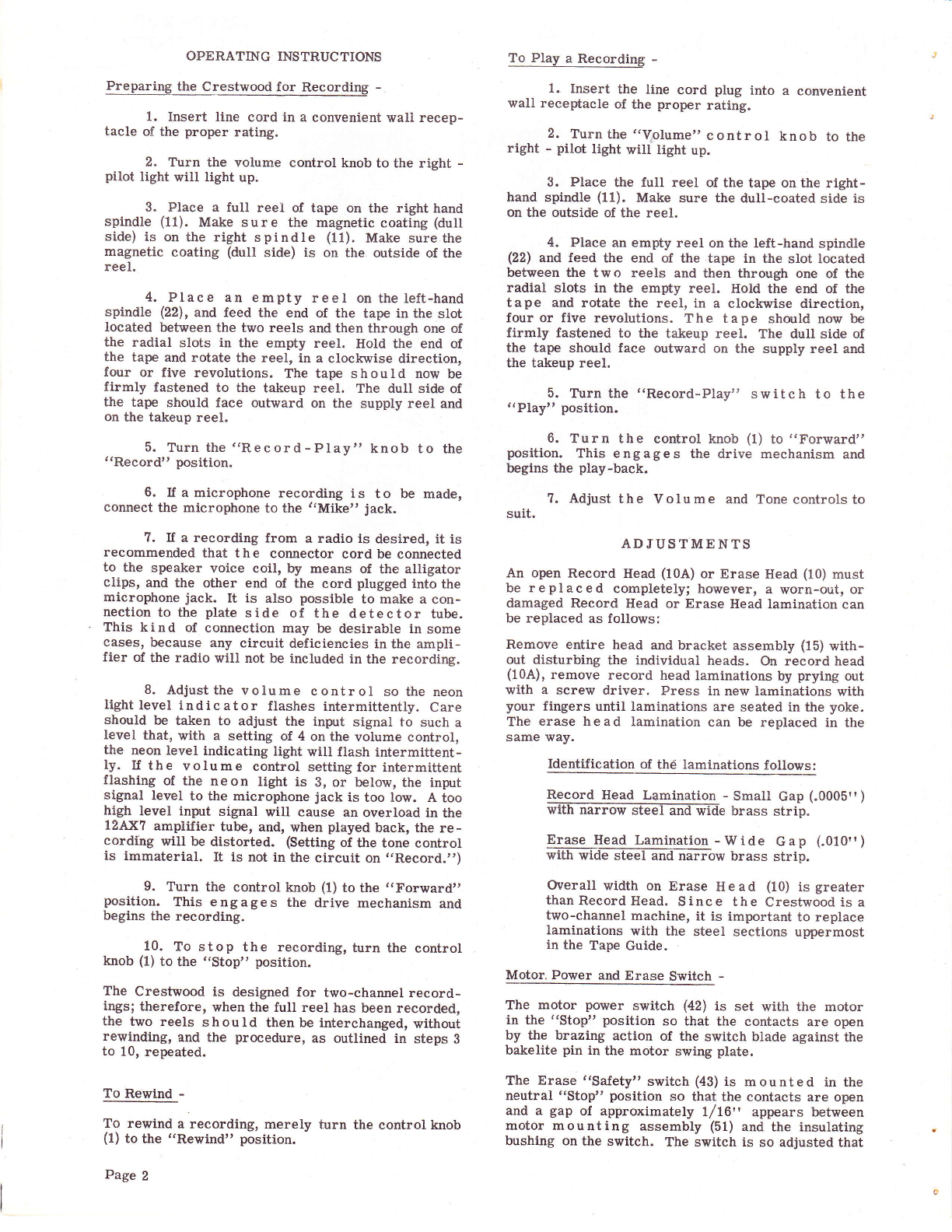
Preparing the Crestwood for Recording -
1. Insert line cord in a convenient wall recep-
tacle of the proper rating.
2. Turn the volume control knob to the right -
pilot light will light up;
3. Place a full reel of tape on the right hand
spindle (11). Make sure the magnetic coating (dull
side) is on the right spindle (11). Make sure the
magnetic coating (dull side) is on the outside of the
reel.
4. Place an empty reel on the left-hand
spindle (22), and feed the end of the tape in the slot
located between the two reels and then through one of
the radial slots in the empty reel. HoId the end of
the tape and rotate the reel, in a clockwise direction,
four or five revolutions. The tape shoutd now be
firmly fastened to the takeup reel. The dull side of
the tape should face outward on the supply reel and
on the takeup reel.
5. Turn the ('Record-Play,'knob to the
"Record" position.
6. If a microphone recording is to be made,
connect the microphone to the ,.Mike, jack.
?. If a recording from a radio is desired, it is
recommended that the connector cord be connected
to the speaker voice coil, by means of the alligator
clips, and the other end of the cord plugged into the
microphone jack. It is also possible to make a con-
nection to the plate side of the detector tube.
This kind of connection may be desirable in some
cases, because any circuit deficiencies in the ampli-
fier of the radio will not be included in the recording.
B. Adjustthe volume control so the neon
light level indic ator flashes intermittenily. Care
should be taken to adjust the input signal to such a
level that, with a setting of 4 on the volume control,
the neon level indicating light will flash intermittent-
ly. If the volume control setting for intermittent
flashing of the neon light is 3, or below, the input
signal level to the microphone jack is too low. A too
high level inpnrt signal will cause an overload in the
lzAxl amplifier tube, and, when played back, the re-
cording will be distorted. (Setting of the tone control
is immaterial. It is not in the circuit on ,,Record.r,)
9. Turn the control knob (1) to the ,,Forward,,
position. This engages the drive mechanism and
begins the recording.
10. To stop the recording, turn the control
knob (1) to the "Stop" position.
The Crestwood is designed for two-channel record-
ings; therefore, when the full reel has been recorded,
the two reels should then be interchanged, without
rewinding, and the procedure, as outlined in steps B
to 10, repeated.
To Rewind -
To rewind a recording, merely turn the control knob
(1) to the "Rewind" position.
Page 2
To Play a Recording -
1. Insert the line cord plug into a convenient
wall receptacle of the proper rating.
2. Turn the ,,Vplume', control knob to the
right - pilot light will tight up.
3. Place the full reel of the tape on the right-
hand spindle (11). Make sure the dull-coated side is
on the outside of the reel.
4. Place an empty reel on the left-hand spindle
(22) and feed the end of the tape in the slot located
between the two reels and then through one of the
radial slots in the empty reel. Hold the end of ttre
tape and rotate the reel, in a clockwise direction,
four or five revolutions. The tape should now be
firmly fastened to the takeup reel. The dull side of
the tape should face outward on the supply reel and
the takeup reel.
5. Turn the '(Record-Play" switch to the
"Play" position.
6. Turn the control knob (1) to t'Forurard"
position. This engages the drive mechanism and
begins the play-back.
7. Adjust the Volume and Tone controls to
suit.
AD JUS TM E NTS
An open Record Head (10A) or Erase Head (10) must
be replaced completely; however, a worn-out, or
damaged Record Head or Erase Head lamination can
be replaced as follows:
Remove entire head and bracket assembly (15) with-
out disturbing the individual heads. On record head
(10A), remove record head laminations by prying out
with a screw driver. Press in new laminations with
your fingers until laminations are seated in the yoke.
The erase head lamination can be replaced in the
same way.
Identification of th6 laminations follows:
Record Head Lamination - Small Gap (.0005" )
ffibrassstrip.
Erase Head Lamination -Wide Gap (.010")
ffibrassstrip.
Overall width on Erase Head (10) is greater
than Record Head. Since the Crestwood is a
two-channel machine, it is important to replace
Iaminations with the steel sections uppermost
in the Tape Guide.
Motor. Power and Erase Switch -
The motor power switch (42) is set with the motor
in the "Stop" position so that the contacts are open
by the brazing action of the switch blade against the
bakelite pin in the motor swing plate.
The Erase "Safety" switch (43) is mounted in the
neutral "Stop" position so that the contacts are open
and a gap of approximately 1/16" appears between
motor mounting assembly (51) and the insulating
bushing on the switch. The switch is so adjusted that

Figure 2
it makes a firm contact when the control knob is set
in the "Forward" position. (ffris switch prevents
accidental erasure while rewinding.)
The Forward Stop Lug -
The forward stop Iug (5?), Figure 3, should be set so
the motor mounting assembly (51) comes to a rest
position against it as soon as the drive roller (56)
makes firm contact with the flywheel (39). Excessive
pressure against the flywheel will prevent the motor
from starting when the control lever is pressed
quickly into the "Forward" position. Insufficient
pressure will result in a slippage and "Wow." The
best setting is to adjust the forward stop lug (57),
Figure 3, lf 16" from the edge of the swing plate (51)
at the point when the drive roller begins to touch the
flywheel.
There is no rewind stop 'adjustment; however, the
rewind drive pulley is located in a hanger whose
position is adjusted by bending the stop lug (a6A)
against the swing plate bushing in a manner that will
allow a clearance between the drive roller (56) and
the rewind pulley (a7) in the (Stop" position. This
will also allow the drive roller to engage the drive
pulley in the "Rewind" position. In this position, the
rewind drive pulley hanger (46) is away from the
stop, pressing the drive roller by means of the
torsion spring that needs no adjustment.
Pressgre Lever and Arm Adjusting Plte -
Set the pressure Iever (16) so that it is vertical when
the control knob is in the ('Forward" or ((Record-
trIayback" position. A I s o adjust the arm adjusting
plate (58), Figure 2, so it will clear the pressure arm
(16) by l/64" when in this position. With normal
adjustments, the tape guide (9) witl move very
slightly, or not at all, when the control is turned from
the "Off" to the "Rewind" position.
Brake Spring -
The brake spring (29) should be adjusted so that the
brake (26) clears the takeup pulley (44) and allows it
to turn freely in either the "Forward" or "Rewind"
position. The pressure in the "Off" or "Stop" pos-
ition should be sufficient to prevent "coasting" of
the reel. If the brake clearance is not equal in the
t'Forward" and fuRewind" positions, then the ad-
justment on the motor transf er Iever (49) is
incorrect.
Transfer Lever -
The transfer lever (49) should be adjusted when the
control is in the c'Off" or "Stop" position. Move
the transfer lever (49) slightly and tightenthe set
screws of the transf er lever (49) when the drive
roller (56) is midway between the rewind drive pulley
(47) and the flywheel (39).
Head Pressure -
The head pressure is ad justed by means of two
screws in the slotted holes in the head bracket (15).
Both the Record Head (10A) and the Erase Head (10)
should be adjusted into the'tape guide block until the
pressure pads on the reverse side show a movement
of slightly less than Lf32'" . This adjustment gives
the necessary 30 grams head pressure against the
shoe for each head. "Wowt' will result if too much
pressure is used at this point.
Head Alignment -
The lateral movement of each head is done by moving
the heads in the required direction by means of the
screws in the slotted holes that hold the heads to the
head bracket (15). The position should be such that
there is no hanging up of the tape pressure guide
when the control lever is turnedtothe "stop"
position.
The Record Head (11A) should be adjusted so that
the air gap in the lamination is at right angles to the
direction of the tape travel.
TROUBLES
Irregular Qpeed "Wow" -
1. FeIt pressure pads in tape guide assembly
(9) worn.
2. Oil or grease on drive roller (56) or pres-
sure roller (20).
3. Head pressure too great (see adjustment on
head pressure). Be careful not to disturb the head
alignment.
Es
Hq
rr!
;{
!o
bo
oe
Page 3

Figure 3
4. Insufficient pressure on pressure roller
(20). Tighten spring (1?) or replace roller (20).
5. Drive roller (56) or pressure roller (26)
eccentric. Allow mechanism to run for 20 minutes.
If after this time the rollers are still eccentric, re-
place with new rollers.
6. Motor shaft binding. Motor shaft should
turn freely when the control knob is in the ,,Off,
position. If necessary, realign bearings by tapping
motor lightly with wooden mallet.
Motor Runs but Mechanism WiIl not errelg -
1. Motor Stop is adjusted incorrecily (see
adjustment on "Pressure Lever and Arm Adjusting
Plate").
2. Drive roller (56) defective. Replace.
1. Check rewind belt (45) or take-up belt (21)
for being broken or loose. Replace.
2. Motor Stop not adjusted properly (see ad-
justment on ('Pressure Lever and Arm Adjusting
Plate").
3. Pressure roller (20) interferes with panel
in rewind position.. Remove pressure roller (20) and
chamfer bottom edge of roller l/16,, x 4bo.
Control Knob Turns but Motor Assembly
-
1. Motor transfer lever (49) set screws loose.
Tighten the set screws with the mechanism in the
"Stop" or "Neutralt' position.
2. Transfer lever (49) Ioose at hub. Replace.
No Positive Detent Position for Motor Assembly -
1. Detent lever (48) loose. Tighten set screws.
2. Check detent lever (48) to see if it is loose
at the hub. If so, replace.
Slow Speed -
1. Low-operating temperature.
Page 4
2. Pressure arm spring (1?).
3. Head pressure too great (see adjustment on
t(Head Pressure").
4. Flywheel (39) shaf t binding. Checkto see
that the s c r e w s holding front and rear plates are
tight and that plates are not warped.
5. Motor shaft binding. Realign bearings by
tapping lightly on the motor.
Machine Will Play Back
bfDoefiA R;Eord=*
1. Defective microphone.
2. Microphone plugged in speaker outlet.
3. Defective amplifier.
High Background Noise (Hiss) -
1. Defective bias oscillator tube or circuit.
2. Defective tape.
3. Defective Record-Playback Head.
4. Record head magnetized. Demagnetize
with 60-cycle AC air core coil.
Incomplete Erase -
1. Erase Voltage po\trer too low.
2. Defective 6C4 oscillator.
3. Erase head open. Replace.
4. Poor contact on Record-play switch.
Poor Recording -
1. Head g a p not at right angles to tape (see
adjustment on "Head Alignment").
2. Overloading.
3. Defective, or damaged, head.
4. Head lamination damaged or worn.
5. Poor contact of head to tape caused by worn
felt pressure pad.
Mechanism Runs Forward but Will not Rewind,

@F- ffi
@# m
ffi
A PHOTOFACT ''EXPLODED'' VIEW
O Howord W. Soms & Co., lnc. 1949
ts
HU
rr rl
;{
PO
l$O
9E
Page 5

f;$
{i[
.L5j
;w;
*-$tu;
g'l {rtt @(Lt r.'.t:g.l)
Figure 5
Figure 4
Figure 6
Page 6

ts
Hffi
FEE
;€
po
*rO
gs
ot
E
Glo
6
E
A
c!
€
A
€
c
a
ld
o
{
F
!.t
c
o. +F
rt
.9
L
et
s
cs
c{
.E
ts I
t
L
c
s
c\
+I+
3
.o
!
o;
r
E
oa, {lo
gg
+rc{
oo
+)P
o. o.
1J +J
Oo i
oo
&l{
$rt}{
d.(J
oo
t< tr
02to
(dd
d)d)
EI
U
tr
=
tl,
I
us'
'nX
7
OP
Sd
bu
Zod
6E
&,O
6
z3
i, ox
b)
ir O
<:
b()
o
I
o
U'
o
z
6
d
a
u
(,
z
n
6
E
d
Hu'
n
r{h H
la
/a.I
\€?z ar ut
L*g
ho
lrl
6
tr
LJ
|,-@Fll''
@+f a
I \:y
@
A
€l
o
L
9>
H,',
a
ei
ils ft.
lJr lr'-
o
Olr.
tlX
J}Fil,,
t
g
4
o
o
o
€
(
o
h
{{}
r-\
\y
o
l&
o
--t
(9) r
Ol|.
Yq>
o urE
N /h\
inr9\g'
n
(a) q
>flHl,'
tlnl
Page 7
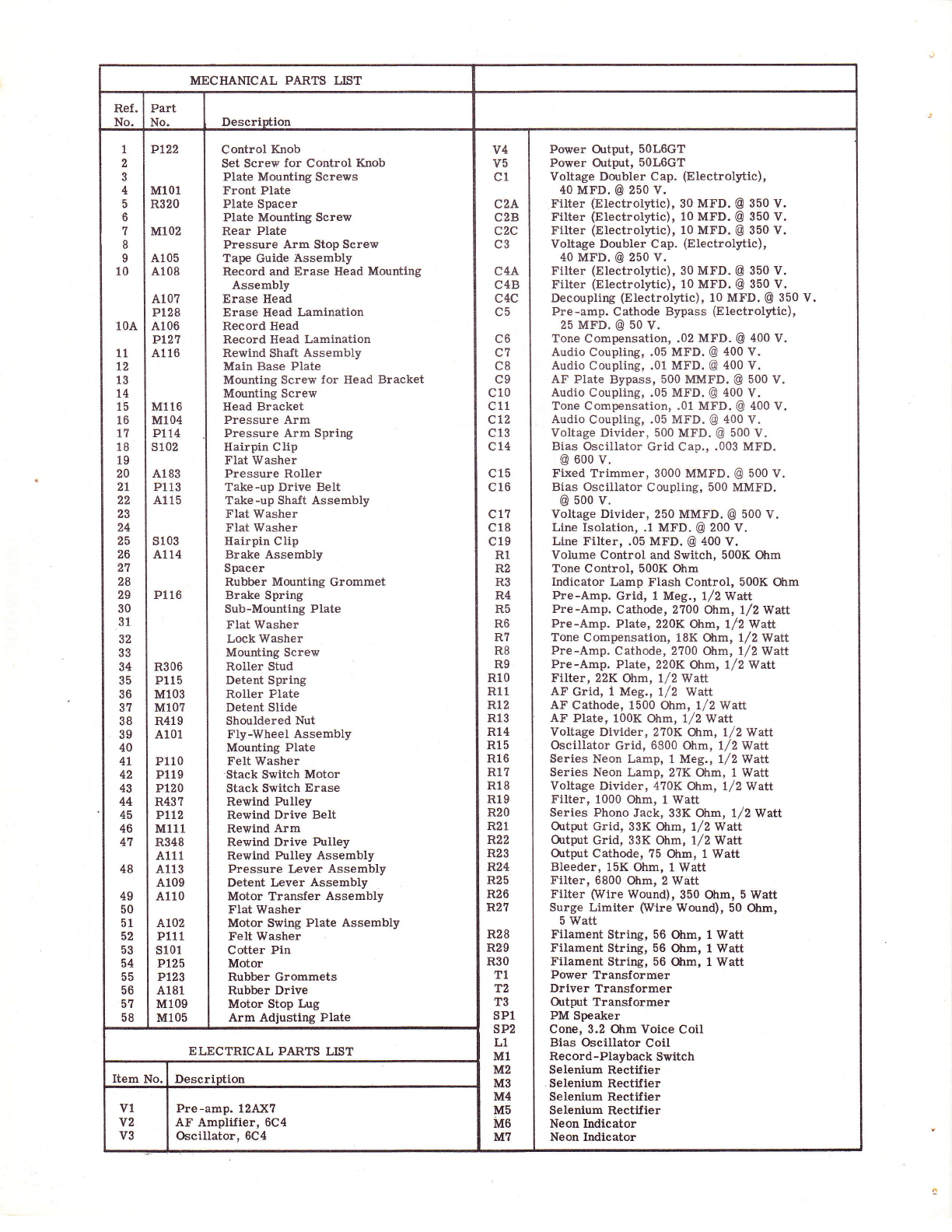
MECHAMCAL PARTS Lr;T
Ref.
N^ Part
N^ Descriution
I
2
3
4
5
6
7
I
I
10
10A
11
12
13
14
15
16
1?
18
19
20
2t
22
23
24
25
26
21
28
29
30
31
32
33
34
35
36
37
38
39
40
4L
42
43
44
45
46
41
48
49
50
51
52
53
54
55
56
51
58
Pl22
M101
R320
M102
A105
A108
A10?
p128
A106
PI2'I
A116
M116
M104
P114
s102
A183
Pl13
A115
s103
A114
P116
R306
Pl15
Ml03
Ml07
R419
A101
P110
Pl19
Pl20
R43?
Pttz
Ml11
R348
A111
A113
A109
A110
A102
Pl11
s101
P125
Pl23
A181
M109
Ml05
Control Knob
Set Screw for Control Knob
Plate Mountlng Screws
Front Plate
Plate Spacer
Plate Mounting Screw
Rear Plate
Fressure Arm Stop Screw
Tape Guide Assembly
Record and Erase Head Mounting
Assembly
Erase Head
Erase Head Lamination
Record Head
Record Head Lamination
Rewlnd Shaft Assembly
Main Base Plate
Mounting Screw for Head Bracket
Mounting Screw
Head Bracket
Pressure Arm
Pressure Arm Spring
Hairpin Clip
FIat Washer
Pressure Roller
Take-up Drive Belt
Take-up Shaft Assembly
Flat Washer
Flat Washer
Hairpin Clip
Brake Assembly
Spacer
Rubber Mounting Grommet
Brake Spring
Sub-Mounting Plate
Flat Washer
Lock Washer
Mounting Screw
Roller Stud
Detent Spring
Roller Plate
Detent Slide
Shouldered Nut
Fly-\{heel Assembly
Mounting Plate
Felt Washer
'Stack Switch Motor
Stack Switch Erase
Rewind Pulley
Rewind Drive Belt
Rewind Arm
Rewind Drive Pulley
Rewind Pulley Assembly
Pressure Lever Assembly
Detent Lever Assembly
Motor Transfer Assembly
Flat Washer
Motor Swing Plate Assembly
Felt Washer
Cotter Pin
Motor
Rubber Grommets
Rubber Drive
Motor Stop Lug
Arm Adjusting Plate
v4
v5
c1
c2A
c2B
c2c
c3
c4A
c4B
c4c
c5
C6
c1
c8
c9
c10
c11
c12
c13
c14
c15
c16
c1?
c18
c19
R1
R2
R3
R4
R5
R6
R7
R8
R9
R10
R11
Rt2
R13
R14
R15
R16
R1?
Rl8
Rl9
R20
R21
F"22
R23
F"24
R25
R26
R27
R28
R29
R30
T1
T2
T3
sP1
sP2
L1
M1
M2
M3
M4
M5
MO
M7
Power Ortput, 50L6GT
Power Ortput, 5OLOGT
Voltage Doubler Cap. (Electrolytic),
40 MFD. @ 250 V.
Filter (Electrolytic), 30 MFD. @ 350 V.
Filter (Electrolytic), 10 MFD. @ 350 V.
Filter (Electrolytic), 10 MFD. @ 350 V.
Voltage Doubler Cap. (Electrolytic),
40 MFD. @ 250 v.
Filter (Electrolytic), 30 Mtr.D. @ 350 V.
Filter (Electrolytic), 10 MFD. @ 350 V.
Decoupling (Electrolytic), 10 MFD. @ 350 V.
Pre-amp. Cathode Bypass (Electrolytic),
25 MFD. @ 50 V.
Tone Compensation, .02 MFD. @ 400 V.
Audio Coupling, .05 MFD. @ 400 V.
Audio Coupling, ,01 MFD. @ 400 V.
AF Plate Bypass, 500 MMFD. @ 500 V.
Audio Coupling, .05 MFD. @ 400 V.
Tone Compensation, .01 MFD. @ 400 V.
Audio Coupling, .05 MFD. @ 400 V,
Voltage Divider, 500 MFD. @ 500 V.
Bias Oscillator Grid Cap., .003 MFD.
@ 600 v.
Fixed Trimmer, 3000 MMFD. @ 500 V,
Bias Oscillator Coupling, 500 MMFD.
@ 500 v.
Voltage Divider, 250 MMFD. @ 500 V.
Line Isolation, .1 MFD. @ 200 V.
Line Filter, .05 MFD. @ 400 V.
Volume Control and Switch, 500K Ohm
Tone Control, 500K Ohm
Indicator Lamp Flash Control, 500K Ohm
Pre-Amp. Grid, 1 Meg., 1/2 Watt
Pre-Amp. Cathode, 2?00 Ohm, l/2Watt
Pre-Amp. Plate, 220K Ohm, 112 Watt
Tone Compensation, 18K Glm, 1,/2 Watt
Pre-Amp. Cathode, 2700 Ohm, l/2Waltt
Pre-Amp. Plate, 220K Ohm, 1/2 Watt
Filter, 22K Ohm, 1/2 Watt
AF Grid, I Meg., l/2 w^tt
AF Catlrode, 1500 Otrm, 1/2Watt
AF Plate, 100K Ohm, l/2Watt
Voltage Divider, 2?0K Ohm, l/2Watt
Oscillator Grid, 6800 Ohm, 1/2 Watt
Series Neon Lamp, 1 Meg., 1/2 Watt
Series Neon lamp, 2?K Ohm, 1 Watt
Voltage Divider, 4?0K Otrm, l/2$latt
Filter, 1000 Ohm, 1 Watt
Series Phono Jack, 33K Ohm, 1/2 Watt
Ortprt Grid, 33K Otrm, l/2Walt
Ortput Grid, 33K Otrm, l/2Watt
Ortput Catlode, ?5 Ohm, 1 Watt
Bleeder, 15K Ohm, l Watt
Filter, 6800 Ohm, 2 Watt
Filter (Wire Wound), 350 Ohm, 5 Watt
Surge Limiter (Wire Wound), 50 Ohm,
5 Watt
Filament String, 56 Ohm, I'iy'att
Filament String, 56 Ohm, I Watt
Filament String, 56 Ohm, 1 Watt
Power Transformer
Driver Transformer
OrtErt Transformer
PM Speaker
Cone, 3.2 Ohm Voice Coil
Bias Oscillator Coil
Record-Playback Switch
Selenium Rectifier
Selenium Rectifier
Selenium Rectifier
Selenium Rectifier
Neon Indicator
Neon hdicator
ELECTRICAL PARTS LIfIT
Item No. Descriotion
v1
v2
V3
Pre-amp. 12AX?
AF Amplifier, 6C4
Oscillator, 6C4
Table of contents


