HARTING Ha-VIS RF-R500 User manual

HARTING
Issue / 版1.0
Version / 版1.0
Status / ステータス: 2014-08 / English/日本語
Ha-VIS RF-R500 RFID Reader
Assembly Manual / 組立てマニュアル
People | Power | Partnership

ii
HARTING Electric GmbH

i
Ha-VIS RF-R500 - Assembly Manual / Issue 1.0
English
Title
Ha-VIS RF-R500 RFID Reader
Assembly manual
- English version -

ii
HARTING Electric GmbH
Ha-VIS RF-R500 - Assembly Manual
English
All brand and product names are trademarks or registered trademarks of the owner
concerned.
1st Edition 2012, revised 08/14
© HARTING Electric GmbH & Co. KG, Espelkamp
Author: HARTING
Editor: HARTING
All rights reserved, including those of the translation.
No part of this manual may be reproduced in any form (print, photocopy, microlm or any
other process), processed, duplicated or distributed by means of electronic systems without
the written permission of HARTING Electric GmbH & Co. KG, Espelkamp.
Subject to alterations without notice.
Printed on bleached cellulose. 100% free from chlorine and acid.

iii
Ha-VIS RF-R500 - Assembly Manual / Issue 1.0
Contents
English
About this Manual .............................................................................................................................................. v
Subject........................................................................................................................................................................... v
Audience........................................................................................................................................................................ v
Before you begin............................................................................................................................................................ v
Ha-VIS RFID documentation ........................................................................................................................................ vi
Explanation of the symbols........................................................................................................................................... vi
Typographical conventions ........................................................................................................................................... vi
Feedback ...................................................................................................................................................................... vi
Safety Instructions / Warnings - Read before start-up ! ................................................................................. 1
1. Reader Family Ha-VIS RF-R500-p / RF-R500-c ................................................................................................ 3
1.1 Performance features..........................................................................................................................................3
1.2 Available Reader types ....................................................................................................................................... 3
1.3 Available Accessories .........................................................................................................................................3
2. Installation .......................................................................................................................................................... 4
3. Terminals............................................................................................................................................................. 5
3.1 Antenna connection ............................................................................................................................................5
3.1.1 Power supply connection on X1 ............................................................................................................... 6
3.2 Interfaces ...........................................................................................................................................................7
3.2.1 Power Supply via PoE (Power over Ethernet) on X2 ............................................................................... 7
3.2.2 Ethernet-Interface on X2 (10/100Tbase) ................................................................................................. 8
3.2.3 USB-Interface X3 (Host Communication)................................................................................................. 8
3.2.4 USB-Interface X4 (WLAN and Conguration Cloning) ............................................................................. 9
3.2.5 RS 232-Interface X6................................................................................................................................. 9
3.2.6 RS 485-Interface X6............................................................................................................................... 10
3.3 Digital Inputs X5................................................................................................................................................ 11
3.4 Outputs..............................................................................................................................................................12
3.4.1 Digital Outputs X5 .................................................................................................................................. 12
3.4.2 Relays X5 ............................................................................................................................................... 13
4. Operating and Display Elements .................................................................................................................... 15
4.1 Status LEDs ......................................................................................................................................................15
4.2 Reset Push Button ............................................................................................................................................ 16
4.3 Reader Power adjustment.................................................................................................................................16
4.3.1 EU Reader (EN 302 208) .......................................................................................................................16
4.3.2 U.S. Readers.......................................................................................................................................... 17
4.3.3. CN-Reader ............................................................................................................................................. 18
4.3.4 Japan Reader ........................................................................................................................................ 18
5. Radio Approvals............................................................................................................................................... 19
5.1 Europa (CE) ......................................................................................................................................................19
5.2 USA (FCC) and Canada (IC)............................................................................................................................. 19
5.2.1 USA (FCC) and Canada (IC) warning notices........................................................................................ 19
5.2.2 Label Information ................................................................................................................................... 21
5.2.3 Installation with FCC / IC Approval......................................................................................................... 21
5.2.4 USA (FCC) and Canada (IC) approved antennas.................................................................................. 21
5.3 China................................................................................................................................................................. 22
5.4 Japan ................................................................................................................................................................22
6. Technical Data .................................................................................................................................................. 24

iv
HARTING Electric GmbH
Ha-VIS RF-R500 - Assembly Manual
English
Figures
Figure 1 Installation drawing..................................................................................................................................... 4
Figure 2 Connection Overview .................................................................................................................................5
Figure 3 External antenna connection ANT1-4 and X1 for the power supply........................................................... 6
Figure 4 Connection for the power supply................................................................................................................ 6
Figure 5 LAN and PoE connection ...........................................................................................................................7
Figure 6 USB-Interface for host communication....................................................................................................... 8
Figure 7 USB-Interface for external WLAN interface................................................................................................ 9
Figure 8 RS 232 interface pin-outs on X6.................................................................................................................9
Figure 9 Wiring example for connecting the RS 232 interface ............................................................................... 10
Figure 10 RS 485 interface pin-outs on X6...............................................................................................................10
Figure 11 Optocoupler pin-outs IN1 – IN5................................................................................................................ 11
Figure 12 Internal and possible external wiring of the optocouplers......................................................................... 11
Figure 13 Optocoupler outputs OUT1-2 ...................................................................................................................12
Figure 14 Internal and possible external wiring of the optocoupler outputs OUT1-2................................................ 13
Figure 15 Relay output pin-outs REL1-3 ..................................................................................................................13
Figure 16 Internal and possible external wiring of the relay output .......................................................................... 14
Figure 17 Position of the reset switches T1 and T2..................................................................................................16
Figure 18 Equipment Classication according to ETSI EN 301 489: Class 2.......................................................... 19
Tables
Table 1 Reader types ..............................................................................................................................................3
Table 2 Optional reader accessorie.........................................................................................................................3
Table 3 Connection terminals.................................................................................................................................. 5
Table 4 Push button function................................................................................................................................... 5
Table 5 External antenna connection...................................................................................................................... 5
Table 6 Pin assignment for power supply................................................................................................................6
Table 7 Maximum cable length if PoE is used.........................................................................................................8
Table 8 Standard factory conguration of the Ethernet connection......................................................................... 8
Table 9 Successfully tested WLAN sticks ...............................................................................................................9
Table 10 RS 485 interface pin-outs......................................................................................................................... 10
Table 11 Required external series resistor Rext .......................................................................................................12
Table 12 Conguration of the status LEDs.............................................................................................................. 16
Table 13 Calculation of the output power................................................................................................................ 17

v
Ha-VIS RF-R500 - Assembly Manual / Issue 1.0
Contents
English
About this Manual
Subject
This book describes the assembly of the RFID Reader Ha-VIS RF-R500 from HARTING.
The instructions given in this manual are based on advantageous boundary conditions.
HARTING does not give any guarantee promise for perfect function in cross environments and
does not give any guaranty for the functionality of the complete system which incorporates the
subject of this document.
HARTING call explicit attention that devices which are subject of this document are not
designed with components and testing methods for a level of reliability suitable for use in or in
connection with surgical implants or as critical components in any life support systems whose
failure to perform can reasonably be expected to cause signicant injury to a human. To avoid
damage, injury, or death, the user or application designer must take reasonably prudent steps
to protect against system failures.
Using the devices described in this document in the transportation market, the rights of third
parties may be injured. Harting can give no warranty that the rights of third parties are not
infringed by the use of the devices. If you plan such usage, please contact us at HARTING, to
clarify potential patent or intellectual property rights issues.
HARTING assumes no responsibility for the use of any information contained in this manual
and makes no representation that they free of patent infringement. HARTING does not convey
any license under its patent rights nor the rights of others.
Audience
This book is intended for application developers who want to develop applications with Ha-VIS
RF-R500.
Before you begin
This book assumes familiarity with RFID.
vi
HARTING Electric GmbH
Ha-VIS RF-R500 - Assembly Manual
English
Ha-VIS RFID documentation
This book is part of the Ha-VIS RFID documentation set. Visit http://www.HARTING.com to
obtain the latest version of the Ha-VIS RFID documentation and additional information and
resources.
Explanation of the symbols
The following symbols are used in this software guide:
WARNING
This text describes warning notes that indicate a low-level source of danger. If not avoided,
human damage to property may result.
ATTENTION
This text describes warning notes that indicate a low-level source of danger. If not avoided,
damage to property may result.
Note
This symbol describes general notes supplying important information concerning one or more
operating steps. It also provides references to further information supplied within this manual.
Typographical conventions
This manual uses the following typographical conventions to describe the software interface:
Format Meaning Example
blue (in normal text) Link to other chapters
Link to external web pages
Ha-VIS RFID - Getting Started Guide
http://www.HARTING.com
italic blue Paths; folder c:/Programme/HA-VIS/RFID
bold Names of modules and other
important items
EventType
bold italic Names of characteristics or similarly OnApplicationMessage
Feedback
We would like to receive your opinions, suggestions, and feedback on this documentation.
You can email comments and suggestions to the Ha-VIS RFID documentation team at
[email protected]. Although we do not reply to emails sent to this address, we read all
suggestions with interest.

1
Ha-VIS RF-R500 - Assembly Manual / Issue 1.0
English
Safety Instructions / Warnings
Safety Instructions / Warnings - Read before start-up !
• Thedevicemayonlybeusedforthepurposeintendedbythemanufacturer
• WheninstallingthedeviceinareascoveredunderUS47CFRPart15aminimum
separationof25cmbetweenantennaandthehumanbodymustbemaintained.
• Theoperationmanualshouldbekeptreadilyavailableatalltimesforeachuser.
• Unauthorizedchangesandtheuseofsparepartsandadditionaldeviceswhichhavenot
beensoldorrecommendedbythemanufacturermaycausere,electricshocksorinjuries.
Suchunauthorizedmeasuresshallexcludethemanufacturerfromanyliability.
• Theliability-prescriptionsofthemanufacturerintheissuevalidatthetimeofpurchaseare
validforthedevice.Themanufacturershallnotbeheldlegallyresponsibleforinaccuracies,
errors,oromissionsinthemanualorautomaticallysetparametersforadeviceorforan
incorrectapplicationofadevice.
• Repairsmayonlybeundertakenbythemanufacturer.
• Installation,operation,andmaintenanceproceduresshouldonlybecarriedoutbyqualied
personnel.
• Useofthedeviceanditsinstallationmustbeinaccordancewithnationallegalrequirements
andlocalelectricalcodes.
• Whenworkingondevicesthevalidsafetyregulationsmustbeobserved.
WARNING
Specialadviceforwearersofcardiacpacemakers:
Althoughthisdevicedoesn‘texceedthevalidlimitsforelectromagneticeldsyoushouldkeep
aminimumdistanceof25cmbetweenthedeviceandyourcardiacpacemakerandnotstayin
theimmediateproximityofthedevice’santennaforanylengthoftime.
ATTENTION
ThereaderHa-VISRF-R500-pofferstheoptiontosupply24VDContheantennaoutputs.
Ifthevoltageisapplieddirectlytoanantenna,theantennacanbedestroyedandcausere
(seesystemmanualsection4.4CFG3).
Thispowermustonlybeusedincombinationwithanexternal,optionalantennamultiplexer.
Observe before beginning with installation procedures.
• InaccordancewithEN50110-1/-2(VDE0105Part100),qualiedpersonnelonly
areallowedtocarryouttransport,installation,commissioningandmaintenancetasks.
GuidelinescontainedinIEC60364andHD384(DINVDE0100)aswellasnational
accidentpreventionregulationsmustbeadheredto.
• Installconnectionandsignalwiresensuringthatthebuscommunicationisnotimpairedby
inductiveorcapacitiveinterferences.
• Theelectricalinstallationmustbecarriedoutinaccordancewiththerelevantregulations
andstandards(protectiveearthconnection,wirecross-sectionsandsoforth).
• Ensurecorrectpolaritywhenconnectingthesupply.

2
HARTING Electric GmbH
Ha-VIS RF-R500 - Assembly Manual
English
Electrical Safety
Deviceisdesignedforoperationwithasafetyextralowvoltage(SELV)inaccordancewithIEC
950/EN60950/VDE0805.
ATTENTION
SuppliedbyNECClass2orLPSPowerSupplyonly.

3
Ha-VIS RF-R500 - Assembly Manual / Issue 1.0
Reader Family Ha-VIS RF-R500-p / RF-R500-c
English
1. Reader Family Ha-VIS RF-R500-p / RF-R500-c
1.1 Performance features
TheReaderhasbeendevelopedforreadingpassivedatacarriers,so-called„SmartLabels“,
usinganoperatingfrequencyintheUHFrange.
1.2 Available Reader types
ThefollowingReadersareavailable:
Reader type Description
Ha-VISRF-R500-p-EU DeviceversionforEuropewithPoE
Ha-VISRF-R500-c-EU DeviceversionforEuropewithoutPoE
Ha-VISRF-R500-p-US DeviceversionforUSAwithPoE
Ha-VISRF-R500-c-US DeviceversionforUSAwithoutPoE
Table 1 Reader types
1.3 Available Accessories
Thefollowingoptionalaccessoriesarecurrentlyavailable:
Identication Description
Protectioncap
Ha-VISRF-R500
ProtectioncapswithPGcableglandforIP64
DINrailmountingkit MountingofthereaderontoDINrail
Table 2 Optional reader accessorie
4
HARTING Electric GmbH
Ha-VIS RF-R500 - Assembly Manual
English
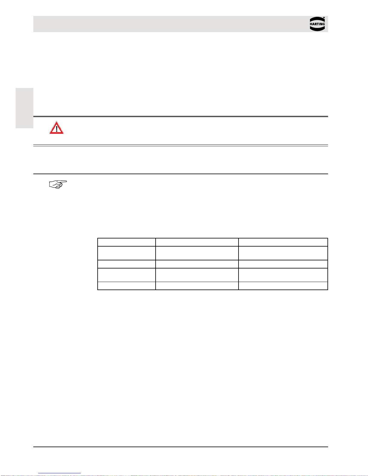
2. Installation
TheReaderisdesignedforwall-mount,includingoutdoors.Holesformountingonawallare
providedinthehousing.
Note
InTurkey,RFIDsystemsmayonlybeinstalledindoor.
Itisnotnecessarytoopenthereaderhousing.
Figure 1 Installation drawing
5
Ha-VIS RF-R500 - Assembly Manual / Issue 1.0
Terminals
English
3. Terminals
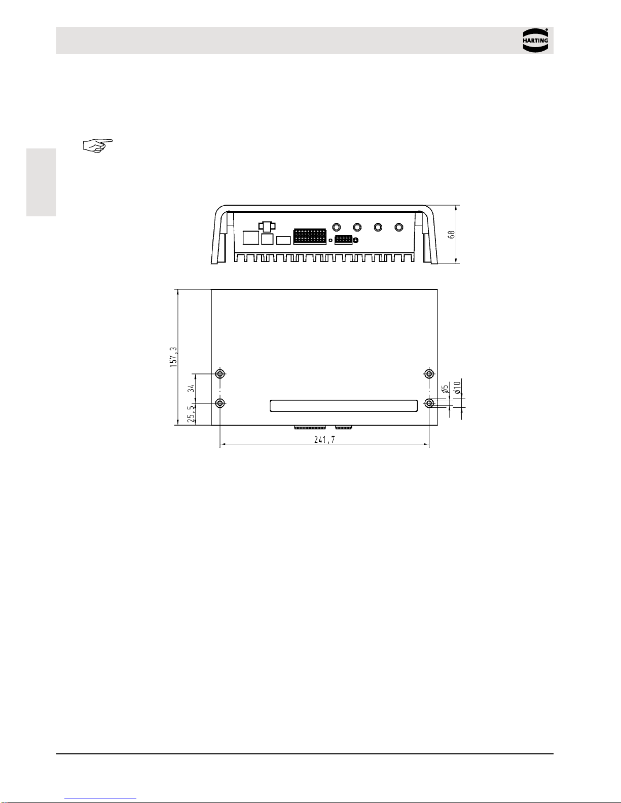
Onthelowersideofthereaderhousingthedifferentcableconnectorsarepositioned.Fig.2
showsthearrangementoftheconnectorsandTable3showswhichconnectionforthedifferent
cablesareusedfor.Table4showstheavailablepushbuttons.
ANT1X1
X3 X4 X5 T1 X6
T2
X2
ANT2 ANT3 ANT4
Figure 2 Connection Overview
Connector Description
ANT1-4 Connectionoftheexternalantennas(Impedance50Ω)
X1 Powersupply24VDC±5%
X2 10/100Base-TnetworkconnectionwithRJ45(withPoE)
X3 USBinterfaceforhostcommunication
X4 USBinterfaceforWLAN-Sticks
X5 Digitalinputandoutputandrelayoutput
X6 RS232/RS485interface
Table 3 Connectionterminals
Push button Description
T1 Internalpushbuttonforcompletecongurationreset
T2 ExternalpushbuttonforCPU-Reset
Table 4 Push button function
3.1 Antenna connection
ATTENTION
ThereaderHa-VISRF-R500-pofferstheoptiontosupply24VDContheantennaoutputs.
Ifthevoltageisapplieddirectlytoanantenna,theantennacanbedestroyedandcausere
(seesystemmanualsection4.4CFG3).
Thispowermustonlybeusedincombinationwithanexternal,optionalantennamultiplexer.
TheexternalSMAantennaconnectorsarepositionedonthelowersideofthereader.
ThemaximumtighteningtorquefortheSMAsocketsis0.45Nm(4.0lbfin).
ATTENTION
Exceedingthetighteningtorquewilldestroytheplug.
Terminal Description
ANT1-4 Connectionforexternalantennas(inputimpedance50Ω)
Table 5 External antenna connection

6
HARTING Electric GmbH
Ha-VIS RF-R500 - Assembly Manual
English
Figure 3 External antenna connection ANT1-4 and X1 for the power supply
3.1.1 Power supply connection on X1
Thesupplyvoltageof24VDChastobeconnectedtoTerminalX1.
Terminal Abbreviation Description
X1/Pin1 VDC Vcc–supplyvoltage24VDC±5%
X1/Pin2 GND Ground–supplyvoltage
Table 6 Pin assignment for power supply
Figure 4 Connection for the power supply
ATTENTION
AnoperationofanHa-VISRF-R500-pviaanexternalpowersupplyandPoweroverEthernet
(PoE)atthesametimecancauseinterferencesduringoperation.
ApowersupplyviaPoEandoveranexternalpowersupplyatthesametimeisnot
recommended.

7
Ha-VIS RF-R500 - Assembly Manual / Issue 1.0
Terminals
English
3.2 Interfaces
3.2.1 Power Supply via PoE (Power over Ethernet) on X2
Optionalthereader(onlyHa-VISRF-R500-p)canbepoweredviatheLANconnectoronX2
withtheuseofaPoE„PoweroverEthernet“powersupplyaccordingtoIEEE802.3at*,Class4
(30/25,5Watt).TheDCsupplycanbeachievedviathefreepin’s4,5and7,8(Midspan-
Power).Alsoa“PhantomPowering”(Inline-Power)viathesignalpins1,2,3,and6ispossible.
*Fordetailedtechnicalinformationregardingthe802.3atstandard,pleaserefertothemost
recenteditionofthecorrespondingIEEEspecication.
Figure 5 LAN and PoE connection
Note
TakecareifPoEisusedthemaximumreaderoutputpowerofthereadermustbelimitedto
1Watt.
Itmustbeensuredthatthereaderissuppliedwith42,5VDC(48VDC–cablelosses)atleast.
ThisfunctionalityisonlyavailablewiththereadermodelsHa-VISRF-R500-p-EUandHa-VIS
RF-R500-p-US.
IfPoveroverEthernetisusedWLANisnotavailable.
ATTENTION
AnoperationofanHa-VISRF-R500-pviaanexternalpowersupplyandPoweroverEthernet
(PoE)atthesametimecancauseinterferencesduringoperation.
ApowersupplyviaPoEandoveranexternalpowersupplyatthesametimeisnot
recommended.

8
HARTING Electric GmbH
Ha-VIS RF-R500 - Assembly Manual
English
Dependingonthecablecross-sectionthefollowingcabledistancescanbeused.
Cable cross-section (Cat. 5 ... 7) Maximum cable length for PoE
0.4mm ≈30m
0.6mm ≈70m
Table 7 Maximum cable length if PoE is used
3.2.2 Ethernet-Interface on X2 (10/100Tbase)
TheReaderhasanintegrated10/100Base-TnetworkportforanRJ45.Connectionismadeon
X2andhasanautomatic“CrossoverDetection”accordingtothe100Base-TStandard.
WithstructuredcablingCat.5cablesshouldbeused.Thisensuresareliableoperationat
10Mbpsor100Mbps.
TheprerequisiteforusingTCP/IPprotocolisthateachdevicehasauniqueaddressonthe
network.AllReadershaveafactorysetIPaddress.
Network Address
IPaddress 192.168.10.10
Subnet-Mask 255.255.255.0
Port 10001
DHCP AUS
Table 8 Standard factory conguration of the Ethernet connection
Note
TheReaderincludesaDHCP-ableTCP/IPinterface.
3.2.3 USB-Interface X3 (Host Communication)
TheUSBsocketontheboardisterminalX3.Thepinoutisstandardized.Thedatarateis
reducedto12Mbit(USBfullspeed).AstandardUSB-cablecanbeused.
Figure 6 USB-Interface for host communication
Note
ThelengthoftheUSB-cablecanbeamax.of5m(20inch).Itisnotallowedtouselonger
cables.

9
Ha-VIS RF-R500 - Assembly Manual / Issue 1.0
Terminals
English
3.2.4 USB-InterfaceX4(WLANandCongurationCloning)
TheUSB-PortX4canbeusedforastandardWLANUSBstick
Figure 7 USB-Interface for external WLAN interface
Note
ItispossibletousestandardWLANUSBsticks.Itmustbeensuredthatthisstickcontainsa
„Ralink“Chipsatz„RT2500USB“or„RT73“.
ForexamplethefollowingWLANsticksaresuccessfullytestedwiththeHa-VISRF-R500:
Manufacturer Description Model
Buffalo Wireless-NNFinitiHighPower WLI-UC-G300HP-EU
Buffalo Wireless-NNFiniti WLI-UC-G300N-EU
Cisco/Linksys WirelessNetworkUSBAdapter WUSB100
Netgear Wireless-G54USBAdapter WG111v3
Table 9 Successfully tested WLAN sticks
CongurationCloning
TheRFIDReaderHa-VISRF-R500supportsfullcongurationcloning.Thecongurationofthe
RF-R500canbestoredonaUSBstick,forexampleviatheHa-VISRFIDcongsoftwareorthe
webinterface.IftheUSBstickwiththecongurationlesisinsertedintothereader(interface
X4),thefullcongurationisautomaticallyloadedonrebootoftheRF-R500.
3.2.5 RS 232-Interface X6
TheRS232interfaceisconnectedonX6.Thetransmissionparameterscanbeconguredby
meansofsoftwareprotocol.
Figure 8 RS 232 interface pin-outs on X6

10
HARTING Electric GmbH
Ha-VIS RF-R500 - Assembly Manual
English
Figure 9 Wiring example for connecting the RS 232 interface
3.2.6 RS 485-Interface X6
TheconnectionoftheRS485interfacetakeplaceviatheX6connectoraswell.Theinterface
parametercanbeconguredviasoftwareprotocols.
Figure 10 RS 485 interface pin-outs on X6
Abbreviation Description
GND RS485–GND
A- RS485–(A-)
B+ RS485–(B+)
Table 10 RS 485 interface pin-outs
3.2.6.1 Address assignment of RS 485 for bus operation
ForbusoperationtheReadercanbeassignedtherequiredbusaddressviasoftware.
Theaddressisassignedbythehostcomputer.Thesoftwareisusedtoassignaddresses“0”
through“254”totheReader.
ApossiblynecessaryterminationoftheRS485buscanalsobeconguredbysoftware.
Note
SinceallReadersarefactorysetwithaddress„0“,theymustbeconnectedandconguredone
aftertheother.
11
Ha-VIS RF-R500 - Assembly Manual / Issue 1.0
Terminals
English
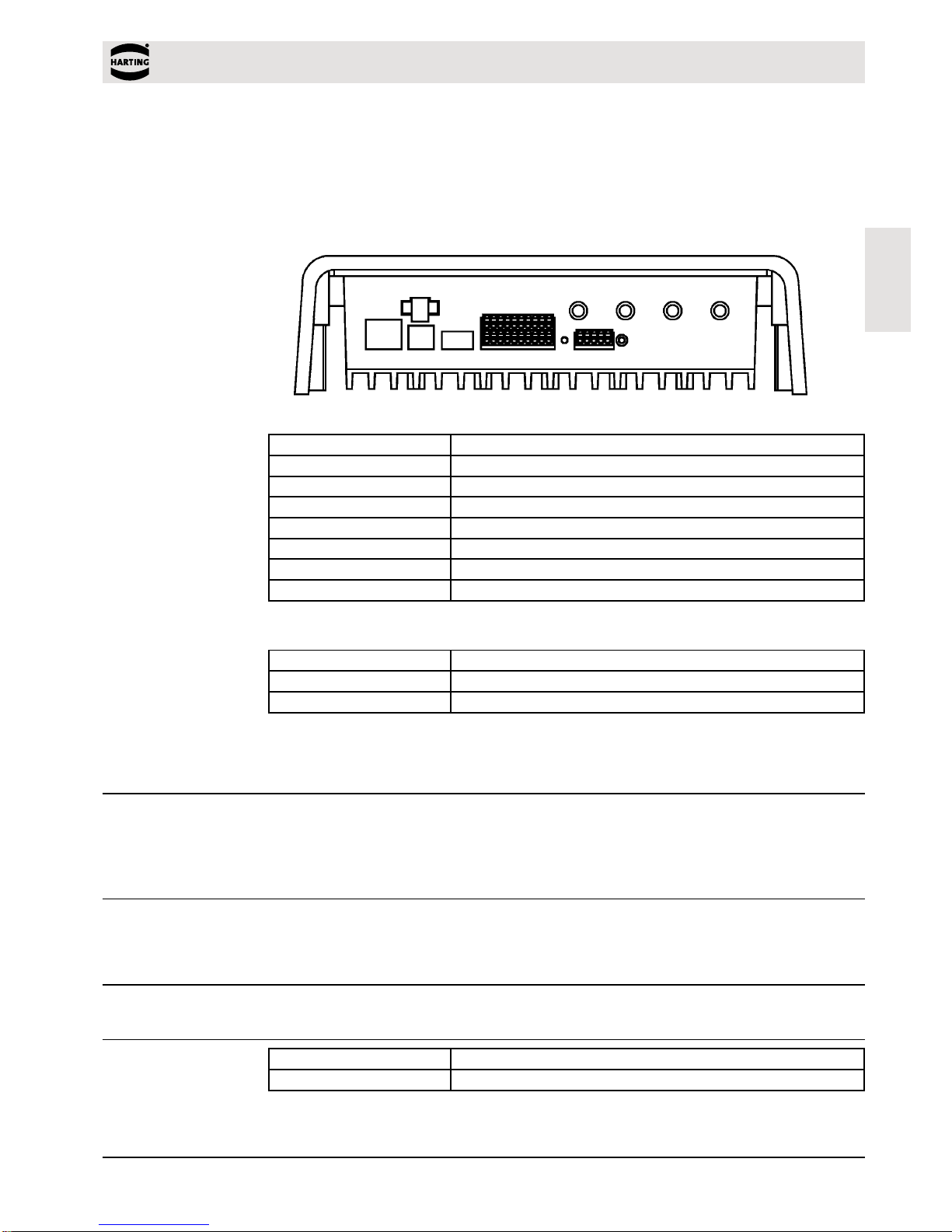
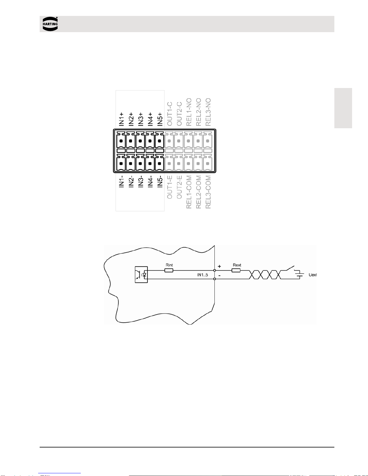
3.3 Digital Inputs X5
TheoptocouplersonTerminalX5aregalvanicallyisolatedfromtheReaderelectronicsand
mustthereforebeexternallysupplied.
Figure 11 Optocoupler pin-outs IN1 – IN5
Figure 12 Internal and possible external wiring of the optocouplers
Optocoupler input (X5 / IN1-5):
TheinputLEDassociatedwiththeoptocouplerisconnectedinternallytoaseriesresistorof
500Ω.Forsupplyvoltagesofgreaterthan10Vtheinputcurrentmustbelimitedtomax.20mA
bymeansofanadditionalseriesresistor(seetable11).
Table11showsthenecessaryexternalresistorsforvariousexternalvoltagesUext.

12
HARTING Electric GmbH
Ha-VIS RF-R500 - Assembly Manual
English
External voltage Uext Required external series resistor Rext
5V...10V -
11V...15V 270Ω
16V...20V 560Ω
21V...24V 820Ω
Table 11 Required external series resistor Rext
Note
Theinputisconguredforamaximuminputvoltageof5...10VDCandaninputcurrentof
max.20mA.
Polarityreversaloroverloadontheinputwilldestroyit.
3.4 Outputs
3.4.1 Digital Outputs X5
Optocoupler output (X5/1-2):
Thetransistorconnections,collectorandemitter,oftheoptocoupleroutputaregalvanically
isolatedfromtheReaderelectronicsandarecarriedtotheoutsidewithoutanyinternalancillary
circuitryonterminalX5.Theoutputmustthereforebepoweredbyanexternalpowersupply.
Figure 13 Optocoupler outputs OUT1-2
Table of contents
Popular Card Reader manuals by other brands


Salto
Salto NCoder EC Series installation guide

KeyMatrix
KeyMatrix KeyMaster AC-1100 Technical reference manual

OBID
OBID i-scan ID ISC.LRU2000-A-EU installation instructions

ddm hopt+schuler
ddm hopt+schuler 855-S1610040400 manual

Farpointe Data
Farpointe Data MCR-30 quick start guide

Hama
Hama 56123 Quick reference guide


