HARVEY T-60S User manual

INSTRUCTION MANUAL
Operation Instructions
Wood Lathe
Model: T-60S

1
Contents
Appreciation Letter To Users......................................................................................................2
Limited Warranty............................................................................................................................ 3
General Safety Rules.....................................................................................................................4
Introduction......................................................................................................................................5
Features............................................................................................................................................ 5
Features Identification.................................................................................................................. 6
Optional Accessories.................................................................................................................... 6
Specifications..................................................................................................................................7
Power Supply.................................................................................................................................. 7
Assembling and Adjustment.......................................................................................................8
Base........................................................................................................................................... 8
Unpacking................................................................................................................................8
Packing Contents................................................................................................................... 8
Legs Installation..................................................................................................................... 9
Tool Storage Bracket............................................................................................................ 9
Comparator Brackets..........................................................................................................10
Spindle Shield....................................................................................................................... 10
12”Swing Away Extension Bed..................................................................................... 11
20”Extension Bed (Optional)...........................................................................................12
Operation........................................................................................................................................13
Control Panel.........................................................................................................................13
Speed Range Adjustment.................................................................................................. 14
Recommended Turning Speed Table............................................................................. 14
Tool Rest Base (Banjo).......................................................................................................15
Tool Rest................................................................................................................................15
HeadStock and TailStock...................................................................................................15
Spur Centers Installation/Removing.............................................................................. 15
Face Plate Installation and Removing........................................................................... 16
Tailstock Quill....................................................................................................................... 16
Live Centers Installation/Removing............................................................................... 16
General Maintenance.................................................................................................................. 17
Trouble Shooting......................................................................................................................... 18
Wiring Diagram............................................................................................................................. 19
Inspection Certificate..................................................................................................................20
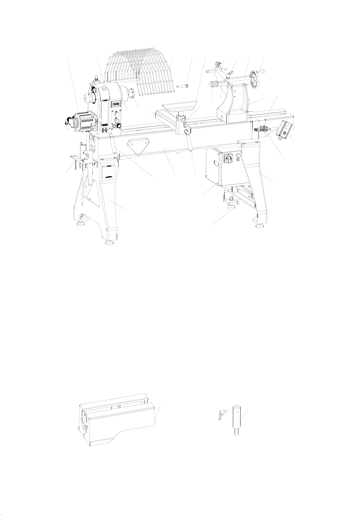
Exploded View and Parts List...................................................................................................21

2
Letter of Appreciation
Dear Woodworker:
Thank you for your purchase of the T-60 Wood Lathe and welcome to the
woodworking family of Harvey Industries.
We understand that you have a choice when purchasing machines and we appreciate
the confidence you have in our products. Every product sold by Harvey Industries has
been carefully designed, engineered and crafted from a woodworker's perspective.
Today, we offer high-performance machines with innovative solutions that meet the
needs of woodworkers and their ever-evolving craft.
We appreciate your business and thank you again for becoming a part of the Harvey
Industries family.

3
Limited Warranty
New woodworking machines sold by Harvey Industries carry a one-year warranty from the
date of shipping. Harvey Industries guarantees that all new machines sold are free of
manufacturers’ defective workmanship, parts and materials. For any parts determined by
Harvey Industries Co., Ltd. to be a manufacturer’s defect, we will repair or replace at no
charge. We require the defective item/part be returned to Harvey Industries. In the event
the item/part is determined to be damaged due to lack of maintenance, cleaning or
misuse/abuse, the customer will be responsible for the cost to replace the item/part, plus all
related shipping charges. This limited warranty does not apply to natural disasters, acts of
terrorism, normal wear and tear, product failure due to lack of maintenance or cleaning,
damage caused by accident, neglect, lack of or inadequate dust collection, misuse/abuse
or damage caused where repair or alterations have been made or attempted by others.
Harvey Industries Co., Ltd is not responsible for additional tools or modifications sold or
performed (other than from/by Harvey Industries Co., Ltd.) on any Harvey Industries
Co., Ltd. woodworking machine. Warranty may be voided upon the addition of such
noted tools and/or modifications, determined on a case-by-case basis.
Normal user alignment, adjustment, tuning and machine settings are not covered by
this warranty. It is the responsibility of the user to understand basic woodworking
machinery settings and procedures and to properly maintain the equipment in
accordance with the standards provided by the manufacturer.
Parts, under warranty, are shipped at Harvey Industries Co., Ltd cost either by common
carrier, UPS Ground service or similar method. Technical support to install
replacement parts is primarily provided by phone, fax or email. The labor required to
install replacement parts is the responsibility of the user.
Harvey Industries is not responsible for damage or loss caused by the Freight
Company or other circumstances not in our control.
Only new machines sold to the original owner are covered by this warranty.
Warning -- no portion of these materials may be reproduced without written approval
from Harvey Industries Co., Ltd.

4
General Safety Rules
Please operate the lathe with awareness of the potential for injury. If you have any doubts
about safety, please contact your local dealer before using.
Warning! Failure to follow the listed rules may result in serious personal injury.
TO ENSURE SAFE USE, READ THIS MANUAL BEFORE OPERATING THE TOOL.
ALWAYS USE A FULL-FACE SHIELD. A full-face shield will protect your eyes and face.
KEEP THE WORK AREA CLEAN and have good lighting.
WEAR PROPER APPAREL. Do not wear loose fitting clothing, gloves, neckties, rings,
bracelets or other jewelry, which may get caught in moving parts. Non-slip footwear is
also recommended. Secure long hair.
DISCONNECT THE MACHINE from the power supply before servicing and changing
accessories.
NEVER LEAVE THE MACHINE RUNNING UNATTENDED. Do not leave the lathe
unless it is turned “OFF” and completely stopped.
USE THE RIGHT TOOL. Do not use a tool or attachment to do a job for which it was not
intended or designed.
TIGHTEN ALL CLAMP HANDLES on the headstock, tailstock, and the tool rest before
operating the lathe.
Before turning a large wood piece, it is advisable to reduce the excess before mounting
the stock to the lathe. When turning a large wood piece, the turner should not stand in
line with the workpiece in order to avoid being struck by a wood piece ejected by an
imbalance.
Hold the tool handle firmly to avoid the rebound.

5
Introduction
Turbo lathes are designed and built to satisfy the most imaginative fantasies of
woodworkers. With outstanding new features, superior performances and so many user-
friendly considerations, Turbo lathes make turning an unprecedented experience.
Features
> High grade cast iron structure for headstock beds and stands to secure maximum
stability
> All beds are precisely ground to a mirror like surface for smooth operation
> Driven by an advanced YFD variable speed motor with variable speeds 60-3500 RPM
> Digital wide-angle speed readout with blue backlight
> Extraordinarily high torque at low speeds for ease of working on large work piece
> Oversized alloy spindle supported by three precision bearings
> Easy belt changing without removing spindle
> Sliding headstock for easy outboard turning
> Unique “Swing-away” Extension Bed System (SEB) for easy tailstock storage
> Heavy duty banjo with easy maneuvering and secure locking
> Cast steel chrome trimmed tool rest
> End mounts for mounting the extension bed for longer center distance
> Side mounts of mounting the extension bed for back turning
> Lower end mounts for mounting the extension bed for outboard turning set up
> Extension bed mounts on both ends of the bed
> Built-in spindle lock and index

6
Features Identification
A: Motor L:Tail stock
B: Belt Access Door M:Tail stock Hand Wheel
C: Head stock N:Tail stock Lock Lever
D: Face Plate O:12” Swing Away Extension Bed
E: Spur Center P:Bed Lock Assembly
F: Tool Rest Lock Handle Q:Leg
G: Tool Support R:Bed
H: Tool Rest Base S:Tool Rest Base Lock Lever
I: Live Center T : Head stock Lock Lever
J: Tail stock Quill U : Tool Kits
K: Quill Lock Handle V : Leveler
W: Electrical Box X:Control Switch
Y: Spindle Guard Z: Rear Support Bracket
Optional Accessories
A: 20 ” Extension Bed B: High Tool Rest
B
A
A
CD
F
G
H
S
T
NO
P
Q
IJ
KM
B
U
L
R
Q
V
W
X
E
YZ

7
Specifications
Models T-60S
Operation Information
Swing Over Bed 24”
Dist. Between Centers 48”
Swing Over Tool Rest Base 20”
Spindle Speeds: High Range 200-3500rpm(Variable)
Low Range 60-1000rpm (Variable)
Floor to Spindle Center Height 44” (NO Leveler )
Headstock Travel Full Length
Max. Outboard Turning Swing 34”
Spindle
Spindle Taper MT#2
Spindle Size 1-1/4x8(RH)TPI
Spindle Bore 5/8”
Spindle Index# 48
Spindle Bearing 2x6209 Front, 1x6208 Rear
Tailstock
Tailstock Taper MT#2
Hole through Tailstock 3 /8”
Tailstock Quill Travel 4-1/2”
Swing Away Standard
Accessories
Tool Rest Width 14”
Face Plate 3”
Swing away Bed Length 12”
Spur Center MT#2
Live Center MT#2
Extension Bed 20”
Electrical And Motor Information
Motor Type AC Induction
Motor Power 3HP
Speed 180-3180rpm
Power Requirement 200-240V/single phase
Power Supply
Warning: For your own safety, have all electrical installations performed under the
supervision of a qualified electrician.
Caution: If the factory installed plug does not fit the outlet, before making any
changes, please seek assistance from a qualified electrician to ensure that the
electrical supply meets local standards. .
Warning:The machine must be connected with three phase and five wire power
supply, otherwise there may be no speed display on the screen.
Voltage: 220V/240V Frequency: 50/60Hz Phase: Single Phase Current: 10.3A

8
Assembling and Adjustment
Warning: The lathe must be powered off during assembly, adjustment or
maintenance.
Base
A level concrete floor is the best location for the lathe. The lathe should be located in a dry
area. Keep the electrical box and motor away from direct sunshine. Plenty of space around
the lathe is good for operations and maintenance.
Unpacking
Report any damage to your shipping agent or dealer immediately as soon as the unit has
been checked for shipping damage.
Check the shipping crate with the following parts list to make sure all parts are intact. If
there are any missing parts please report it immediately to your dealer. Read this manual
thoroughly for assembly, maintenance, operation and safety instructions.
Shipping Contents
Fig. 1
ALathe bed with Headstock, Tailstock,
Tool Rest Base (Banjo),Tool Rest
Q12” Swing away Extension Bed x 1
BLeg Assemblies x 2 L12mm Spring Washer x 2
CKnock Out Rod x 1 M12mm Flat Washer x 2
DFace Plate Wrench x 1 NTool Kits x 1
ELocating Rod x 1 OLevelers x 4
GLive Center x 1 P3” Face Plate x 1
HSpur Center x 1 RM12×40 Bolt x 8
I10mm Hex Wrench x 1 SOperation Manual x 1
J3mm Hex Wrench x
K
M12×20 Bolt x 2
TSpindle Guard USupport Bracket
V
Rear Support Bracket
W
Profiling Center
XProfiling Center

9
Legs Installation
(Refer to Fig. 2)
1. Lift the lathe off the pallet by using a hoist or forklift. Place it on a table or workbench with
sufficient clearance which allows for the support legs to be attached from underneath.
2. Attach the legs to the bed with 12mm hex head screws (A). Then firmly tighten the
screws.
3. After firmly securing the legs to the lathe, carefully lower the lathe onto the floor.
4. Install four leveling feet (B), and tighten four nuts(C) against the legs. (These can be
adjusted later.) Make sure that the lathe does not rock.
Fig.2
Tool Storage Bracket
(Refer to Fig. 3)
The tool storage bracket (D) can be mounted to the left end of the lathe. Use two 12mm
head cap screws (A) with flat (C) and spring washers (B) to secure it to the lathe.
Fig.3
ABC
D
A
C
B

10
Comparator Brackets
(Refer to Fig.4)
Mount the front comparator bracket (C) to the back of the headstock with two M12 socket
head cap screws (D). This bracket can be also used for mounting the spindle shield.
Mount the rear comparator bracket (A) to the back of the tailstock. The bracket has a slot
so it can be aligned with the front comparator bracket. Use two M12 head cap screws (B) to
secure the rear comparator bracket to the tailstock.
Fig. 4
Spindle Shield
(Refer to Fig. 5)
1. Lift up the spring pin (B) and insert the support rod (A) into the bracket hole. Release the
spring pin, slide the rod and you will feel that the spring pin snaps into position.
2.Install the outer collar (C) and tighten the set screw (D).
Fig. 5
A
C
B
D
D
C
B
A

11
12” Swing Away Extension Bed
(Refer to Fig. 6)
To mount the 12” Swing Away Extension Bed (A), you need to attach the hinge (C) to the
hinge axis(B).
Fig. 6

12
20” Extension Bed (Optional)
Refer to Fig.7 -Fig.9
The optional 20” extension bed can be mounted on the lathe in three locations:
A: Right end of bed (as shown in Fig. 7) for up to 56” center distance.
Fig. 7
B: Right leg (as shown in Fig.8) for outboard turning.
Fig.8
C: Front bed (as shown in Fig.9) for convenient operation.
Fig. 9
B
C
A

13
Operation
Notice:
The lathe must be powered off during assembly, adjustment or maintenance.
Please start the lathe by using the lowest speed!
Control Panel
Refer to Fig. 10
Fig.10
1. Emergency Stop Button ---Button A:
2. Start/Stop Button ---Button B:
Turns the lathe ON or OFF.
3. Positions Switch ---Gear Switch C:
“F”: forward; “R”: reverse; “O”: stop
4.Speed Adjustment Knob ---D: .
Change the spindle speed by turning this knob.
Note: If a sudden power failure occurs, the spindle will not re-start automatically when the
power is restored. Turn the Switch C to “O”, then press the button B to reset, and then turn
Switch C to F (forward) or R (reverse).
A
B
D
C

14
Speed Range Adjustment
(Refer to Fig. 11)
The lathe is designed having two speed ranges: Low Range: 60-1000 rpm and High
Range: 2000-3500 rpm.
In each range, the speed can be changed variably by the electronic variable speed
controller.
Follow the steps below to change the speed range:
1. Disconnect the lathe from the power supply;
2. Open the HeadStock Guard which is held by a strong magnetic pad;
3. Loosen the Motor Locking Handle “A”, pull up the Motor Mount Handle to release the belt
tension;
4. Position the belt on the desired speed range pulleys;
5. Turn the spindle hand wheel by hand, ensuring that the belt rotates smoothly and is
engaged with both the motor pulley and the spindle pulley;
6. Tighten the belt by pushing down the motor mount handle, then tighten the motor locking
handle “A”. Close the HeadStock Guard.
Fig. 11
Note: The best belt tension is determined by pressing the belt with one finger. The belt
should deflect about 1/4” -1/2” (about 6-12mm).
Recommended Turning Speed Table
Notice: Please start the lathe by using the lowest speed!
Wood Piece Dia. Rough Turning Normal Turning Sanding
<50mm 1600rpm 3500rpm 3500rpm
50-100mm 800rpm 1600rpm 2500rpm
100-150mm 500rpm 1100rpm 1700rpm
150-200mm 400rpm 800rpm 1250rpm
200-250mm 300rpm 700rpm 1000rpm
250-300mm 250rpm 550rpm 900rpm
300-400mm 200rpm 450rpm 680rpm
400-500mm 150rpm 350rpm 550rpm
500-600mm 100rpm 280rpm 400rpm
≥600mm 80rpm 200rpm 300rpm
BA
C

15
Tool Rest Base (Banjo)
The Banjo is designed with a cam-lock system, it can slide along the bed freely when
unlocked. Loosen the locking handle and move the Banjo to the desired place. Lock the
lever firmly after adjustment.
Tool Rest
The 14″tool support is provided with your lathe as standard equipment. It is designed
to allow the adjustment for height and angle. Loosen the locking lever to raise or lower
the tool rest and angle it to the work. Tighten the handle before operating the Lathe.
The locking lever can be inserted into one of three holes on the tool rest base.
HeadStock and TailStock
Both headstock and tailstock can slide along the bed. Loosen the locking lever and
move the Headstock or Tailstock to a desired place. Tighten the lever firmly after
adjustment.
CAUTION: Always Unplug the lathe from the power source before adjusting the
headstock.
Spur Centers Installation/Removing
(Refer to Fig. 12)
1. Unplug the lathe from the power source.
2. Make sure the taper of the center and the spindle taperred hole are clean and free of
debris. Then push the center into the spindle taperred hole for installation.
3. To remove the center, insert the knockout rod into the back hole in the end of spindle
and tap the center end out.
Fig .12

16
Face Plate Installation and Removing
(Refer to Fig. 13)
1. Unplug the lathe from the power source.
2. Mount the face plate to the work piece.
3. Install the face plate onto the spindle thread and turn it clockwise
4. Insert the lock rod (A) into the hand wheel hole. Hold the rod and tighten the face plate
with the face plate wrench (B).
5. Tighten the set screw on the face plate when you work with the lathe in reverse rotation.
6. Reverse these directions to dismount the Face Plate.
B
A
Fig .13
Tailstock Quill
Loosen the Tail Stock Quill Locking Handle, rotate the Tail Stock Hand Wheel to the
desired Tail Stock Quill position, and then tighten the Tail Stock Quill Locking Handle.
Live Centers Installation/Removing
1. Make sure the taper of the center and the quill hole are clean and free of debris. Push
the center into the quill hole.
2. To remove the center from the tailstock, loosen the tailstock quill locking lever and move
the quill out by turning the quill hand wheel until the quill end is almost inside the tailstock,
then the center can be taken out by hand.

17
General Maintenance
Daily:
Wipe off the dust from the lathe with a soft bench brush.
Apply a coat of wax on the Spindle, Tail Stock Quill and bed.
Monthly:
Check the belt tension.
Check the belt for wear and tear and change the worn and torn belt.
Clean the dust from the belt.
Check the stability of the lathe base.

18
Trouble Shooting
Trouble Probable Cause Remedy
Lathe won’t start.
No incoming power. Check power supply, lead
connections
Problem with driver. Contact Harvey Technical
Service.
Motor fails to
develop full
power.
Undersized wires in power
supply system. Increase supply wire size.
Faulty driver. Contact Harvey Technical
Service.
Worn motor. Replace motor.
Motororspindle
stalls or will not
start.
Excessive cut. Reduce depth of cut.
Improper belt adjustment, or
worn or broken belt. Adjust or replace belt as needed.
Worn spindle bearings. Replace bearings.
Worn motor. Replace motor.
Excessive
vibration.
Workpiece warped, out of
round, has major flaw, or was
improperly prepared for
turning.
Correct problem by planing or
sawing workpiece, or discard
entirely and use new workpiece.
Worn spindle bearings. Replace spindle bearings.
Worn drive belt. Replace drive belt.
Motor mount lock handle is
loose. Tighten lock handle.
Lathe on uneven surface. Adjust leveling feet.
Lathe runs at one
speed only.
Driver is not programmed
properly, or is defective, or
there is loose wiring.
Contact Harvey Technical Service
to help identify problem.
Tools tend to grab
or dig in.
Dull tools. Keep tools sharp.
Tool support set too low. Reposition tool support height.
Tool support set too far from
workpiece.
Reposition tool support closer to
workpiece.
Improper tool being used. Use correct tool for operation.
Tailstock moves
when applying
pressure.
Cam lock nut needs adjusting. Tighten cam lock nut.
Lathe bed and tailstock
mating surfaces are greasy or
oily.
Remove tailstock and clean
surfaces with a
cleaner/degreaser. Re-apply light
coat of oil to Lathe bed surface.

19
Wiring Diagram
Table of contents
Other HARVEY Lathe manuals