HARWI ORCA Series User manual

MANUAL
ORCA
Harwi Holland BV
Lage Dijk 28
5705 BZ Hel ond
the Netherlands
Tel. + 31 (0)492 543355
Fax + 31 (0)492 522305

2
Orca Eng. 9-2004

3
CONTENTS
GENERAL SAFETY REGULATIONS.........................................................................................6
GENERAL INFORMATION ....................................................................................................7
TECHNICAL DATA...............................................................................................................8
TRANSPORT FRAME WITH CRANE/FORKLIFTRUCK ...............................................................9
TRANSPORT BEAM WITH CRANE/FORKLIFTTRUCK ............................................................. 10
SETTING UP THE MACHINE............................................................................................... 11
POSITIONING VERTICAL SLIDE WAY ................................................................................. 12
ADJUSTING THE FRAME....................................................................................................13
ADJUSTING THE FRAME....................................................................................................14
CONNECTING TO THE ELECTRICITY SUPPLY......................................................................15
DIRECTION ROTATION OF THE MAIN SAW-BLADE ............................................................. 16
ADJUSTING THE MEASURE FOR VERTICAL CUTS ................................................................17
ADJUSTING THE MEASURE FOR HORIZONTAL CUTS...........................................................18
VERTICAL CUTTING.......................................................................................................... 19
HORIZONTAL CUTTING ....................................................................................................20
REITERATION STOP ......................................................................................................... 21
STOPS FOR HORIZONTAL CUTS ........................................................................................22
ADJUSTING THE RIVING KNIFE .........................................................................................23
FITTING THE MAIN SAW-BLADE........................................................................................ 24
CLEANING ....................................................................................................................... 25
CHECK BRUSHES ON HORIZONTAL TRACKS .......................................................................26
SMOOTHENING MIDWAY FENCES...................................................................................... 27
SMOOTHENING THE BOTTOM SUPPORT ............................................................................28
ADJUSTING MEASURE ......................................................................................................29
ADJUSTING MEASURE FOR HORIZONTAL CUTTING ............................................................ 30
MALFUNCTIONS ...............................................................................................................31
OPERATING THE SCORING BLADE (OPTIONAL)..........................................................32
OPERATING THE SCORING BLADE (OPTIONAL)..........................................................33
TRANSPORT ROLLERS (OPTIONAL)....................................................... 34
DIGITAL READ OUT (OPTIONAL) ......................................................35
DIGITAL READ OUT (OPTIONAL) ......................................................36
DIGITAL READ OUT (OPTIONAL) ......................................................37
DIGITAL READ OUT (OPTIONAL) .................................................... 38
EXPLODED VIEW TYPE ORCA ............................................................................................ 39
PARTS LIST TYPE ORCA.................................................................................................... 40
EXPLODED VIEW FRAME................................................................................................... 41
PARTS LIST FRAME ..........................................................................................................42
PARTS LIST FRAME ..........................................................................................................43
EXPLODED VIEW ALUMINIUM BACK SUPPORT....................................................................44
PARTS LIST ALUMINIUM BACK SUPPORT ...........................................................................45
EXPLODED VIEW TRK-SYSTEM-L (OPTIONAL)................................................................. 46
PARTS LIST TRK-SYSTEM-L (OPTIONAL) ......................................................................47
EXPLODED VIEW TRK-SYSTEM-R (OPTIONAL) ................................................................ 48
PARTS LIST TRK-SYSTEM-R (OPTIONAL).......................................................................49
EXPLODED VIEW MIDWAY FENCE...................................................................................... 50
PARTS LIST MIDWAY FENCE .............................................................................................51

4
CONTENTS
EXPLODED VIEW TRANSPORT ROLLERS (OPTIONAL).......................................................... 52
PARTS LIST TRANSPORT ROLLERS (OPTIONAL)..............................................................53
EXPLODED VIEW LENGTH STOP ........................................................................................54
PARTS LIST LENGTH STOP................................................................................................ 55
EXPLODED VIEW VERTICAL SLIDEWAY..............................................................................56
PARTS LIST VERTICAL SLIDE WAY .................................................................................... 57
PARTS LIST VERTICAL SLIDEWAY .....................................................................................58
EXPLODED VIEW STOPS FOR HORIZONTAL CUTS...............................................................59
PARTS LIST STOPS FOR HORIZONTAL CUTS ...................................................................... 60
EXPLODED VIEW HINGE FENCE (OPTIONAL) .................................................................. 61
PARTS LIST HINGE FENCE (OPTIONAL)........................................................................62
EXPLODED VIEW EXTRACTION PIPE.................................................................................. 63
PARTS LIST EXTRACTION PIPE.......................................................................................... 64
EXPLODED VIEW MOTOR CARRIAGE..................................................................................65
PARTS LIST MOTOR CARRIAGE ......................................................................................... 66
EXPLODED VIEW OPERATING SYSTEM FENCE ....................................................................67
PARTS LIST OPERATING SYSTEM FENCE (OPTIONAL).........................................................68
EXPLODED VIEW REITERATION STOP................................................................................ 69
PARTS LIST REITERATION STOP .......................................................................................70
EXPLODED VIEW HOUSING............................................................................................... 71
PARTS LIST HOUSING ...................................................................................................... 72
PARTS LIST HOUSING ...................................................................................................... 73
PARTS LIST HOUSING ...................................................................................................... 74
EXPLODED VIEW SPINDLE WITHOUT SCORING UNIT ......................................................... 75
EXPLODED VIEW SPINDLE WITH SCORING UNIT (OPTIONAL).............................................76
PARTS LIST SPINDLE WITHOUT SCORING UNIT.................................................................77
PARTS LIST SPINDLE WITH SCORING UNIT (OPTIONAL) ....................................................78
PARTS LIST SPINDLE WITH SCORING UNIT .......................................................................79

5
APPLIANCES
The Orca vertical panel saws are only to be
used for cutting plastics, wood and wood-like
panels (e.g. chipboard, block board, MDF
etc.)
Maxi u panel sizes:
- for type Orca 1850
4,3 * 1,85 * 0,060 eter
-for type Orca 2150
4,3 * 2,15* 0,060 eter
Cutting of other aterials with the standard
saw-blade is prohibited. Cutting other
aterials with a special saw-blade only with
per ission of anufacturer.
All other appliances except for the above are
i proper use of the achine and therefore
prohibited. The producer cannot be held
responsible for da age as a result of
i proper use. Da age will be recovered fro
the user.
The machine may not be operated, used
or maintained by persons not
acquainted with the dangers o the
machine.
Permission or operating, using and
maintaining the machine have to be
clearly described by a person or persons
responsible within the organisation.
Maintenance has to be perfor ed by the
anufacturer or custo er service.
One has to be acquainted and co ply with
the country's applicable safety regulations.
Only original Harwi parts are to be used.
We cannot give warranty or be held
responsible for da age caused by using non-
original Harwi parts.
The anufacturer cannot be held responsible
for da age caused by changes ade to the
achine by the user.
Re aining risks:
If the achine is co pletely used according
to all safety regulations there still will re ain
so e risks:
- Touching o the saw-blade with the
sawing area.
- Touching o the saw-blade when the
lid is opened
- Breaking o the saw-blade or parts o
the saw-blade hurtling out o the
guard.
- Touching o parts under voltage while
junction box or switch is opened.
- Damage to the hearing by constant
use o the machine without ear
protection.
- Throw out o harm ul dusts or vapours.

6
GENERAL SAFETY REGULATIONS
Harwi Holland B.V. has bestowed great care
on co piling this anual. Read the co plete
anual carefully before operating the
achine.
Person under the age of 18 are not allowed
to work on or with circular sawing achines.
Except for a training progra on a legal
basis.
The achine ay only be operated by
educated personnel or under supervision of
educated personnel.
To avoid touching with rotating saw-blades
ake sure that:
Clothing fits tightly to the body
One works with closed fingers
No rings or other jewellery are worn.
A hairnet is used by long hair.
Be careful when changing the saw-blades.
They are sharp and cause injuries.
Do not re ove woodchips when the saw-
blade is running. Stop the achine first.
Broken saw-blades or defor ed blades are
not to be used. Neither are HSS blades
The applied saw-blade is to be used and
sharpened according to the directions of the
anufacturer.
Sharpening only by co petent crafts en.
Stick to ax. ad issible r.p. . entioned on
the blade. Preferably use noise-reduced saw-
blades.
Flexible hoses of the dust extractor have to
be fro a highly infla able quality
(according to DIN 4102).
The safety guard and other safety
equip ent ay not be re oved or put out
of order.
The pressure pad ay not be cla ped. The
riving knife has to be used every ti e except
for drop-in cuts. The riving knife has to be
adjusted properly.
Asse bling or repairs are only to be
perfor ed if the achine cannot be
switched on. The switch or the ain switch
are to be switched off and locked with for
instance a padlock.
Repairs to the electricity supply are only to
be executed by skilled crafts en. Always
disconnect the achine fro the ains
supply.
When leaving the working area ake sure
that the achine cannot be switched on by
inco petent persons.
It is obligatory to wear a dust- ask, ear
protection and safety glasses.
Take care of a clean working area.
The achine has to be lighted. When using
strip lighting take into account the
stroboscopic effect. A rotating saw-blade
see s to be standing still

7
GENERAL INFORMATION
MANUFACTURER
HARWI Holland B.V.
Lage Dijk 28
5705 BZ Hel ond, the Netherlands
Tel: +31 (0)492-543355
Fax: +31 (0)492-522305
E ail: info@harwi.nl
MACHINE
Vertical panel saw Orca
Type:.....................................................
Machine nu ber:...................................
Manufactured:.......................................
EU DECLARATION OF CONFORMITY FOR MACHINERY
(according to Annex II A of the Machinery Directive)
We, HARWI Holland B.V. Lage Dijk 28, 5705 BZ Hel ond, the Netherlands herewith declare, on
our own responsibility, that the product entioned above, which this declaration refers to, is in
confor ity with the following standards;
EG Machine Directive 98/37/EG, changed in 98/79/EG.
EG Low Voltage Directive 73/23/EWG, changed in 93/68/EWG.
EG-EMV Directive 89/336/EWG, changed in 93/68/EWG
Hel ond, the Netherlands,
Date…………………………………………………………………..(signature)
Quality control………………………..…………………………..(na e)

8
TECHNICAL DATA
MEASURES AND WEIGHTS
Type Orca 1850
2150
Length of cut 4300
4300
Height of cut 1850
2150
Depth of cut 60
60
Speed ain blade rp 5000
5000
Speed scoring blade (optional) rp 13000
13000
Dia eter ain blade Ø 250
250
Dia eter scoring blade (optional) Ø 70
70
Motor power kW 4
4
hp 4
4
Voltage V 400
400
Machine-di ensions:
Length 5300
5300
Depth 1400
1400
Height 2700
3000
Weight kg 600
640
NOISE INFORMATION
Used saw-blade:
A-weighed Equivalent Continuous Noise pressure
Idle 80.7 dB(A)
Loaded 83.3 dB(A)
Measuring perfor ed according to DIN 45635 part 1659. Measured when cutting chipboard
thickness 18 , length 2 eter. Safe deviation can be approx. 3 db(A).
The above entioned values are radiated noise pressures and not necessarily noise pressures
to work safely with this achine. Supple entary easures for ear protection can be
necessary. The following can be of influence:
duration of operations
working area
other noises
Maxi u value ay vary per country. Above infor ation can be used for better valuation of
dangers and risks subsequent to using this achine.
9
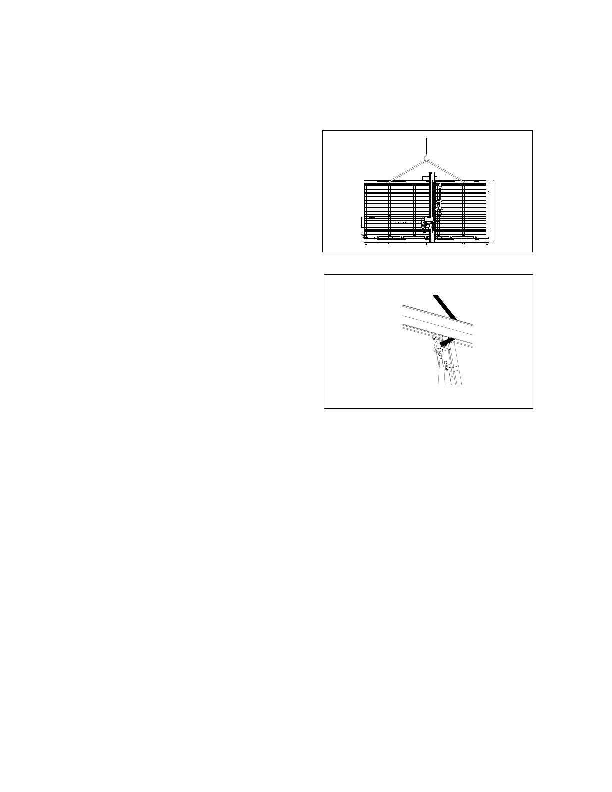
TRANSPORT FRAME WITH CRANE/FORKLIFTRUCK
The rame may only be li ted with the
special cask grips (see ig. 1 and 2)
Recommended carrying capacity o
crane or orkli t
truck:…………….........1000 Kgs.
The fra e ay only be loosened fro the
slings if it is stable on the floor.
The machine may only be installed by
skilled cra tsmen.
Fig. 1
Fig. 2

10
TRANSPORT BEAM WITH CRANE/FORKLIFTTRUCK
The sideway may only be li ted with
the special cask grips (see ig. 3 and 4).
Recommended carrying capacity o
crane or orkli t
truck:……………………………..1000 kgs.
The slide way ay only be lifted with the
special cask grip on the topside of the slide
way.
The vertical slide way ay only be placed on
the fra e after securing the achine to a
flat and solid floor.
The slide way may only be placed on
the rame by skilled cra tsmen.
(See chapter: Positioning vertical slide way).
Fig. 3
Fig. 4

11
SETTING UP THE MACHINE
SETTING UP
1 Place the achine on a flat and solid
floor. The back side of the achine has to
be attainable.
2 Secure the achine to the floor. In both
supports of the achine are holes. Drill
the holes into the floor through these
holes, and secure the achine with
expanding bolts to the floor.
3 Adjust the face plates at both ends of the
achine in such a way that they touch
the floor.
Also adjust the iddle face plate for type
Orca 1850 en 2150.
4 Fasten face plates with the nuts.
5 Re ove the hexagon nut which block the
counter weight (at the botto side of the
track). Secure the hexagon socket head
cap screw ( ounted on the handle of the
depth adjust ent).
6 Connection to the ains supply has to be
perfor ed by an electrical engineer.
7 Check the rotation of the saw-blade.
DUST EXTRACTION
1 If used inside, the achine has to be
connected to a dust extractor.
The dia eter of the connection is 100 or
160 (TRK-syste ).
2 The dust extractor has to be connected
in such a way that otor and dust
extractor are switched on
si ultaneously.
3 The extracting capacity has to be
calculated in such a way that a ini u
air speed of 20 /s is reached at the
connection of the achine.
4 The air speed V is 1450 3 /hour at Vair =
20 /s at a depression of about 2000 Pa.
12
POSITIONING VERTICAL SLIDE WAY
0 Regard the centre of gravity when
re oving the slide way fro the crate or
the supports. Use the cask grips on the
top when lifting the slide way. (see
Transport of the slide way with
crane/forklift truck fig. 3 and 4).
1 Dis antle bearing support at the botto
side of the slide way by re oving the
two bolts (see figure 5).
2 Adjust the two bearings of the slide way
carriage ax. backwards.
3 Place slide way on the fra e.
Notice: At the back side of the slide way is
a T-profile. This has to be lifted over the
tracks (figure 6).
4 Adjust the bearings of the carriage at the
top side of the slide way.
5 Asse ble bearing support on botto
side of the slide way.
6 Push the bearing support tightly against
the adjusting bolts at the front side.
7 Fasten the bearings support with two
M10 bolts.
RELEASE COUNTERWEIGHT
1 Re ove the protruding bolt at the
botto side of the track (figure 7).
2 Insert and tighten the short bolt, stuck
on the grip of the depth adjust ent.
Fig. 5
Fig. 6
Fig. 7
13
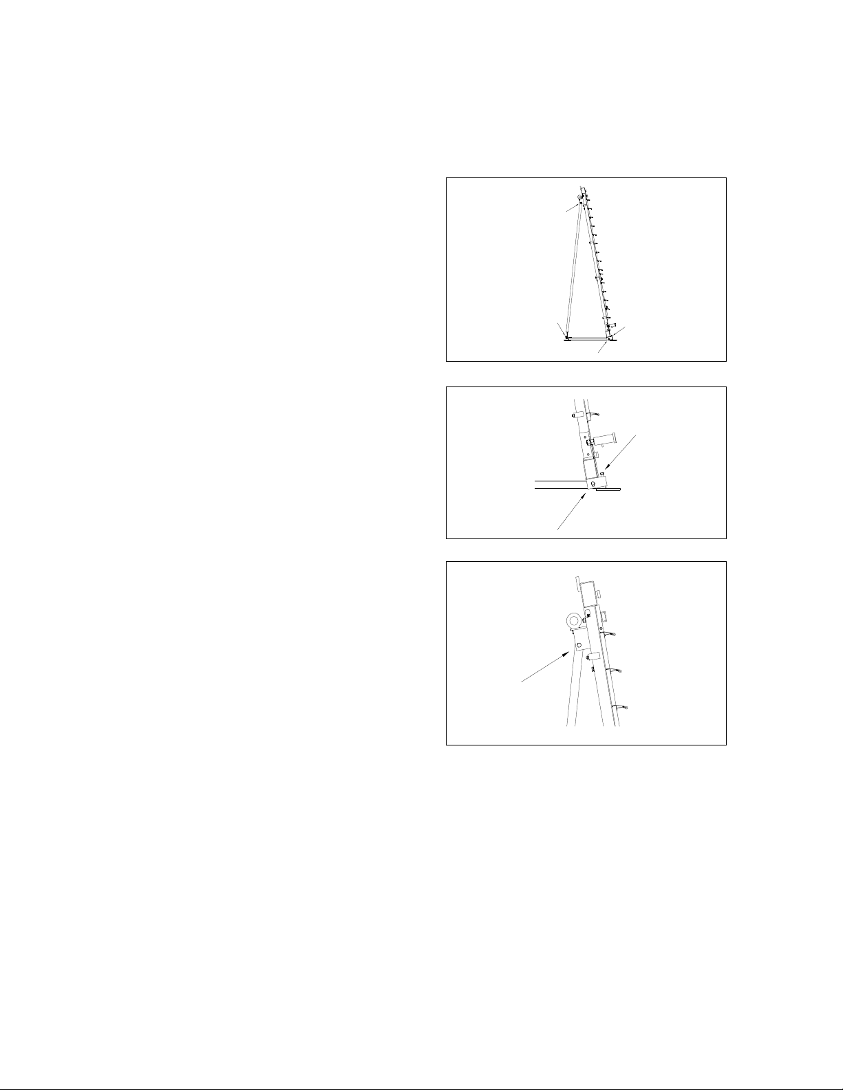
ADJUSTING THE FRAME
In case one o the ollowing
mal unctions occurs, the rame needs
adjusting.
a The vertical slide way cannot be locked
in the notches.
b The fra e is twisted. (The panel is not
fully supported by the alu iniu strips).
0 Overall drawing adjusting points (Fig. 8)
1 Position the vertical slide way near a
vertical support.
2 Loosen the horizontal bolt-nut connection
of the support (Fig. 9).
3 Check if the vertical slide way can be
oved easily fro left to right.
4 If not, adjust the vertical bolts of the
support (Fig. 9). Check oving of the
slide way.
5 Secure the nut of the vertical bolts
without rotating the bolts.
6 Do not secure the horizontal bolt nut
connection at this o ent.
7 Loosen the bolt nut connection of the
vertical supports without re oving the
bolt and the nut (Fig. 10).
Fig. 8
Fig. 9
Fig. 10

14
ADJUSTING THE FRAME
8 Adjust the angle between fra e and
botto at 80º with the M16 nuts (Fig.
11).
9 Attach cables with (lead)weights to the
horizontal bearing track at the sa e
heights as the vertical supports (Fig. 12).
10 Check if the distance between fra e and
cables is identical. If not adjust the M16
nuts of the vertical supports to get the
sa e distance (fig. 11).
11 Fasten the nuts of the vertical supports
(fig. 11).
12 Fasten the bolt nut connection of the
vertical supports (Fig. 10).
13 Fasten the horizontal bolt nut connection
of the fra e support (Fig. 9).
14 Adjust the face plates at both ends of the
achine in such a way that they touch
the floor.
15 Type Orca 1850 and 2150 has also a
iddle face plate. Adjust it the sa e way.
16 Secure the face plates with the nuts.
Check if the vertical slide way can be easily
locked in the notches at the top and botto .
The fra e is adjusted correctly.
Fig. 11
Fig. 12
15
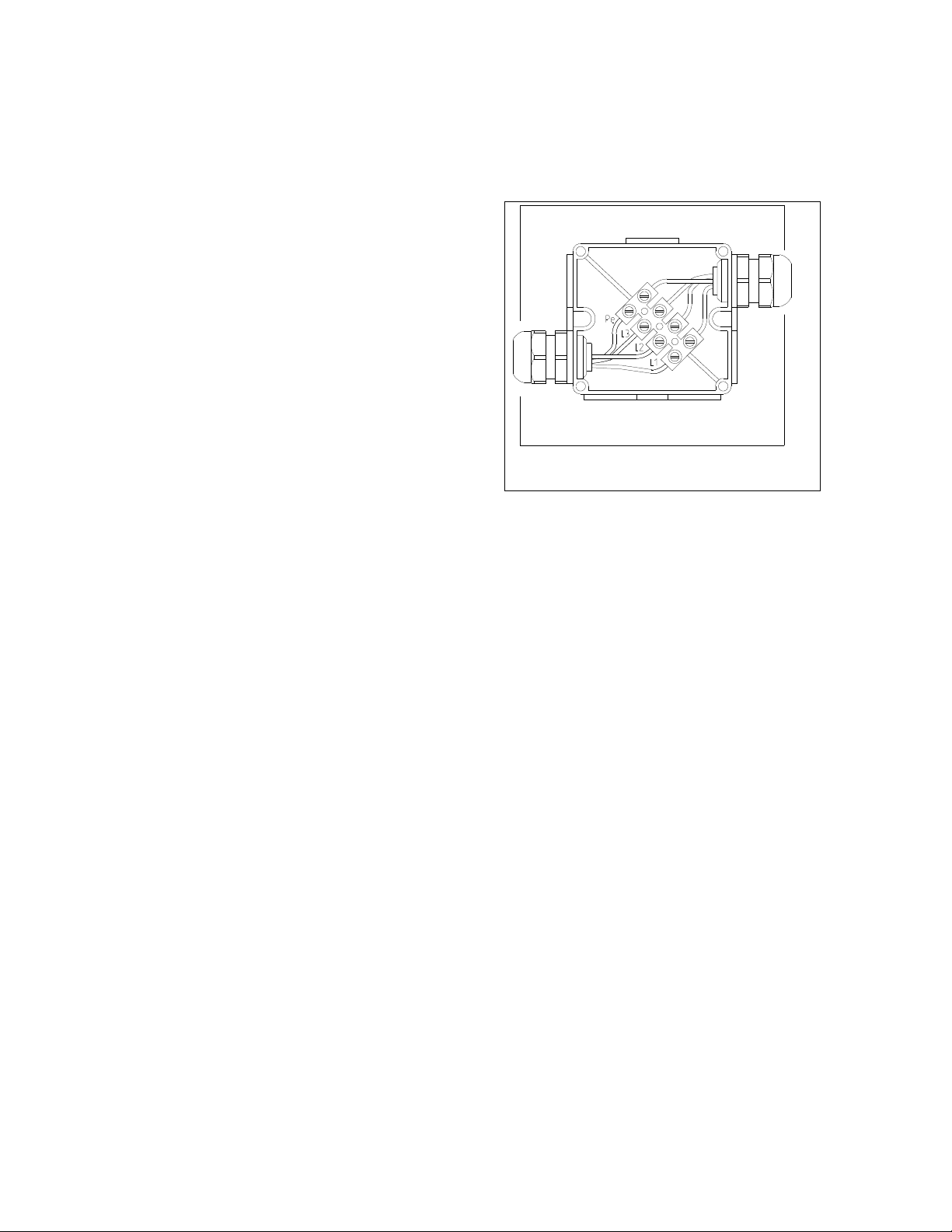
CONNECTING TO THE ELECTRICITY SUPPLY
400V – 3 phase
You will find the wiring diagra in the
switch box.
0 Connecting the achine ay only be
perfor ed by a skilled crafts an.
1 Insert cable with four supply leads with a
dia eter of 1.5 2 into the junction
box at the back side of the fra e. The
quality of the cable has to be ini al
equal to H 07 RN F.
2 The cable has to be connected to the
electric fitting (Figure 13):
the 3 phases (L1, L2, L3)
...................................black or brown
the earth (PE).............yellow /green
3 Close the junction box carefully.
4 Check if the achine is provided with
fuses of 20 A p. slow.
Notice: Check the rotation of the ain saw-
blade *
* The direction of rotation is indicated on
the pressure pad. If the direction is
wrong, interchange two of three phases.
(See first next page spindle rotation).
Fig. 13

16
DIRECTION ROTATION OF THE MAIN SAW-BLADE
0 Block the carriage and put the saw-blade
in vertical position.
The direction of rotation is indicated on
the pressure pad (figure 14).
PROPER DIRECTION IS ANTI-CLOCKWISE
(standing at the left side of the casting)
1 Switch otor on and off.
2 Check if direction is anti clockwise.
WRONG DIRECTION IS CLOCKWISE
(standing at the left side of the casting)
1 Switch otor on and off.
2 Direction is clockwise.
3 Disconnect ains supply.
4 Interchange any two supply leads in the
junction box (at the back side of the
fra e).
5 Close junction box carefully.
6 Connect the ains supply.
Notice: If the saw-blade was turning to the
wrong side the saw-blade ay co e
loose. Check this before operating the
achine.
(see chapter: Changing the saw-blade).
Fig. 14

17
ADJUSTING THE MEASURE FOR VERTICAL CUTS
1 Lock the slide way at the zero point of
the easure scale.
2 Move saw unit upwards.
3 Place length stop at the left or at the
right side of the zero point.
4 Adjust easure and swing the cla p
forwards. Stop cla ps auto atically (Fig
15).
5 If the easure to be adjusted is bigger
than 1000 ove the slide way one
position to the left.
EXAMPLE:
Width of cut has to be 23 c .
Adjust easure at 23 c .
Place the aterial against the alu iniu
cap of the length stop.
Lock the slide way at the zero point of
the easure scale.
EXAMPLE:
Width of cut has to be 123 c .
Adjust easure at 123 c .
Place the aterial against the alu iniu
cap of the length stop.
Lock the slide way at the zero point of
the easure scale
OR
Adjust easure at 23 c .
Place the aterial against the alu iniu
cap of the length stop.
Lock the slide way one position to the
left of the zero point (if the stop was
place at the right side of the zero point).
Fig. 15

18
ADJUSTING THE MEASURE FOR HORIZONTAL CUTS
0 The zero of the easure scale on the
slide way corresponds to the upper side
of the support.
1 Put the saw-blade in horizontal position
(see chapter Horizontal cutting).
2 Set the correct height by eans of the
scale on the slide way (Figure 16).
3 Fasten the knob at the right side of the
otor carriage.
4 Unlock the slide way.
Notice: Always cut fro left to right.
ADJUSTING THE MEASURE FOR
HORIZONTAL CUTTING ON THE MIDWAY
FENCES
0 The zero of the easure scale
corresponds to the upper side of the
idway fence.
1 Put the saw-blade in horizontal position
(see chapter Horizontal cutting).
2 Set the correct height by eans of the
scale on the slide way (Figure 16).
3 Fasten the knob at the right side of the
otor carriage.
4 Unlock the slide way.
Notice: Always cut fro left to right.
Fig. 16

19
VERTICAL CUTTING
LOCKING CONTROLLER VERTICAL CUTS
0 The achine is equipped with a locking
controller against vertical cutting of the
plastic strips. The vertical slide way has
to be locked in the notches and the saw-
unit has to be positioned for vertical
cutting. In case the locking of the vertical
slide way or the positioning of the saw
unit is not done properly, the otor will
not start.
Always cut fro top to botto .
1 Position the otor carriage at the top of
the slide way.
2 Adjust easure and position the aterial
against the alu iniu cap of the length-
stop.
3 Take the handle of the depth
adjust ent.
4 Switch on otor.
5 Push saw unit forward.
6 Pull the saw-blade steadily down through
the aterial (Figure 17).
Meanwhile turn the handle to the left.
7 When the plate is cut, pull the saw-blade
out of the aterial by eans of the
handle.
8 Switch off otor.
9 Swing cla p of length stop upwards.
10 Re ove aterial.
Fig. 17

20
HORIZONTAL CUTTING
PROTECTION HORIZONTAL CUTTING
0 The achine can be equipped with a
anually operated or self- oving panel
support. It prevents da aging the plastic
strips when cutting horizontally. If the
saw-unit is adjusted on the sa e height
as one of the alu iniu supports, the
panel support can be operated anually
or oves auto atically when pushing
the saw unit forward for aking the cut.
The anually operated panel support
can be re-adjusted by using the knob
(Fig. 18A).
Always cut fro left to right.
Notice: If the achine is equipped with a
scoring unit which is not needed at that
o ent, use the 5 allen key to turn it
backwards.
1 Fasten the otor carriage with the knob
at the right side at breast height.
2 Pull back the saw-unit with the handle
and hold it.
3 Pull back the blocking pin and turn the
saw-unit (Fig. 18).
4 Insert blocking pin when the saw-unit is
in its horizontal position.
5 Adjust the saw-unit at the correct height.
6 Block the carriage with the knob at the
right side.
7 Put a panel on the achine.
8 Swing the cla p of the length stop
downwards against the right side of the
panel.
9 Place the aterial against the alu iniu
strip of the length stop.
10 Turn on the otor.
Fig. 18
Fig. 18A
11 Push the saw unit forwards.
12 Cut the aterial steadily fro left to
right.
13 Pull back the saw unit.
14 Turn off otor.
Notice: See to it that the riving knife is
adjusted properly (See chapter adjusting
riving knife).
This manual suits for next models
2
Table of contents


