Hasley Taylor BFM-LR User manual

97093C (Rev. D - 06/16)
BFM-LR
PAGE 1
IMPORTANT
ALL SERVICE TO BE PERFORMED BY AN AUTHORIZED SERVICE PERSON
Fully-Recessed Non-Refrigerated Fountain
FIG. 2FIG. 1
INSTALLER
To assure you install these models easily and correctly, PLEASE READ
THESE SIMPLE INSTRUCTIONS BEFORE STARTING THE INSTALLATION.
CHECK YOUR INSTALLATION FOR COMPLIANCE WITH PLUMBING,
ELECTRICAL, AND OTHER APPLICABLE CODES. After installation, leave
these instructions with the Fountain for future reference.
BFM-LR
IMPORTANT! INSTALLER PLEASE NOTE.
THE GROUNDING OF ELECTRICAL EQUIPMENT SUCH AS TELEPHONE, COMPUTERS, ETC. TO WATER LINES
IS A COMMON PROCEDURE. THIS GROUNDING MAY BE IN THE BUILDING OR MAY OCCUR AWAY FROM
THE BUILDING. THIS GROUNDING CAN CAUSE ELECTRICAL FEEDBACK INTO A FOUNTAIN, CREATING AN
ELECTROLYSIS WHICH CAUSES A METALLIC TASTE OR AN INCREASE IN THE METAL CONTENT OF THE
WATER. THIS CONDITION IS AVOIDABLE BY USING THE PROPER MATERIALS AS INDICATED. ANY DRAIN
FITTINGS PROVIDED BY THE INSTALLER SHOULD BE MADE OF PLASTIC TO ELECTRICALLY ISOLATE THE
FOUNTAIN FROM THE BUILDING PLUMBING SYSTEM.
OWNERS MANUAL
B CA
SIMPLY PUSH IN
TUBE TO ATTACH
TUBE IS SECURED
IN POSITION
PUSH IN COLLET
TO RELEASE TUBE
OPERATION OF QUICK CONNECT FITTINGS
PUSHING TUBE IN BEFORE
PULLING IT OUT HELPS TO
RELEASE TUBE
OPERATION OF QUICK CONNECT FITTINGS
SIMPLY PUSH IN
TUBE TO ATTACH
TUBE IS SECURED
IN POSITION
PUSH IN COLLET
TO RELEASE TUBE
PUSHING TUBE IN BEFORE
PULLING IT OUT HELPS TO
RELEASE TUBE
A B C
1/4” O.D. TUBE
WATER INLET
TO COOLER
3/8” O.D. TUBE CONNECT
COLD WATER SUPPLY
BUILDING WATER
INLET
NOTE: WATERFLOW
DIRECTION
SERVICE STOP
(NOT FURNISHED)

97093C (Rev. D - 06/16)
BFM-LR
PAGE 2
ROUGH-IN DIMENSIONS
FIG. 3

97093C (Rev. D - 06/16)
BFM-LR
PAGE 3
1. Familiarize yourself with the wallbox which should already be placed in the wall. If not, refer to the “Wall frame” Installations before
proceeding.
2. Remove noise pad from paper and locate on bottom back of the basin between the drain and the bubbler holes.
CAUTION: TO INSURE PAD DOES NOT INTERFERE WITH THE HOLE AREAS, TRIM THE PAD SO THERE IS APPROX. 1/2"
CLEARANCE AROUND THE HOLES.
3. Determine location of rough plumbing.
4. Attach basin mounting brackets to basin studs located in the lower corners with two (2) provided wing nuts. Tighten securely.
5. Install basin. Place the upper edge of basin above the hangers in the wall frame. Slide the basin down until it engages the hanger.
Be sure basin is rmly engaged before releasing it.
6. Finish securing basin in place through the mounting bracket using the provided two (2) #8 x 3/4" tap screws and two (2) 11/64" ID
washers. Tighten securely.
7. Install waste tube assembly. Align threaded portion of drain tube assembly with the drain hole in the basin. Place rubber gasket
between the drain assembly and the basin, then screw in the drain plug from above. Tighten the drain plug. Snap the strainer plate
into the drain plug.
8. Install a service stop (not provided) on supply inlet line.
9. Make connection from water outlet to regulator valve assembly using the provided strainer. Insert water line in inlet side of strainer
(see Figures 1 and 2) to positive stop - approximately 3/4"(19 mm). DO NOT SOLDER TUBES INSERTED INTO THE STRAINER AS
DAMAGE TO THE O-RINGS MAY RESULT.
10. Open service stop and operate push button to purge air from system. Check thoroughly for leaks. Check stream height from
bubbler. Stream height is factory set at 45-50 PSI. If supply pressure varies greatly from this, remove items 17 and 18 and adjust
screw on regulator (Item 14). Clockwise adjustment will raise stream and CCW adjustment will lower stream height. For best
adjustment stream height should be approximately 1-1/2" (38 mm) above the bubbler guard. (See Figure 6).
11. Attach regulator housing (Item 13) to front panel (Item 3) with hex nut (Item 16). Install front panel. Hold panel and engage angle on
top edge of panel with lower edge of basin. Swing bottom of panel into place against the wall and secure using panel mounting
screws.
BEFORE STARTING THE INSTALLATION, PLEASE CHECK YOUR INSTALLATION
FOR COMPLIANCE WITH PLUMBING, ELECTRICAL AND OTHER APPLICABLE
CODES
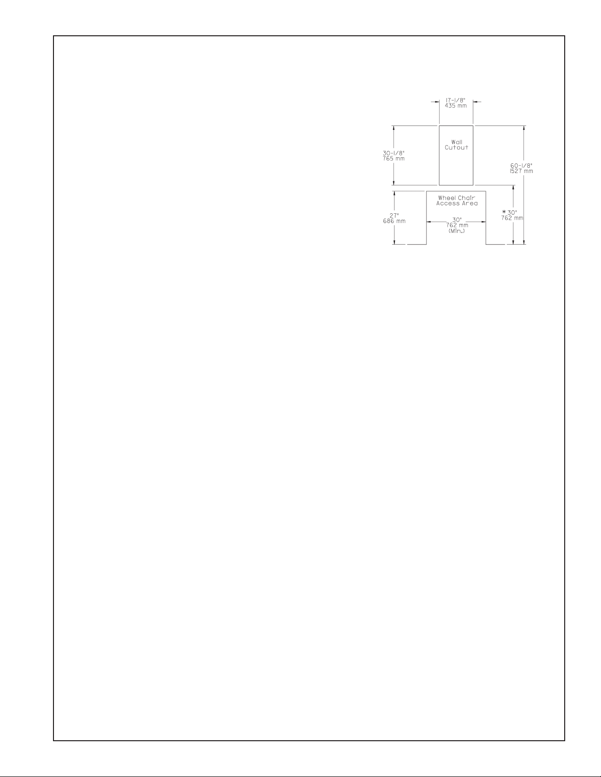
At 30" above the nished oor, cut a rectangular wall opening 17-1/8" wide by
30-1/8" high. This is required to obtain a rim height of 34-1/2" and 36" bubbler spout
height, which is in compliance with ANSI Standard A117.1 (See Fig. 4)
Reinforce wall opening on all sides so that it will adequately support the water
cooler. IT MUST SUPPORT UP TO 150 LBS. and provide a means of securing the
frame assembly in place.
Install rough-in plumbing. See Fig. 3 for location of supply water inlet and for loca-
tion of waste water outlet.
Install frame assembly in the wall opening with front edge ush with nished wall
face. Secure frame through holes in top and sides to wall support members with
5/16" diameter bolts or lag screws (not supplied). Six (6) bolts/screws are required.
CAUTION: BE SURE THAT FRAME ASSEMBLY IS SQUARED IN ITS LOCATION
AND DO NOT USE LESS THAN REQUIRED QUANTITY AND DIAMETER OF THE
FASTENERS.
WALLFRAME INSTALLATION INSTRUCTIONS
INSTALLATION INSTRUCTIONS
FIG. 4
WALL ROUGH-IN
* 30" (762)mm) to bottom of wall cut-out required to
obtain 34-1/2" (876mm) rim height (Check local codes)

97093C (Rev. D - 06/16)
BFM-LR
PAGE 4
FOR PARTS CONTACT YOUR LOCAL DISTRIBUTOR OR VISIT OUR WEBSITE - WWW.HALSEYTAYLOR.COM
2222 CAMDEN COURT
OAK BROOK, IL 60523
630.574.3500
FIG. 6
CORRECT STREAM HEIGHT
ITEMIZED PARTS LIST
ITEM NO. PART NO. DESCRIPTION
1000002412
734253251550
23021C
62257C
100147140560
160270508650
161637308640
51546C
100322740560
62300C
66346C
75588C
56121C
74050011
98536C
55996C
1
2
3
4
5
6
7
8
9
10
11
11a
11b
12
13
14
Basin - Stainless Steel
Mounting Frame
Front Panel - Stainless Steel
Tube - Regulator In
Gasket
Strainer Plate - Chrome
Drain Plug - Chrome
Bubbler - Chrome
Gasket - Bubbler (2-Req’d)
Tube Assy - Bubbler
Tube - Waste
Nut - Slip Joint 1-1/4
Elbow - Drain
Noise Pad
Kit - Push Button Assy
Strainer
FIG. 5
FRONT PANEL
FIG. 7
TROUBLE SHOOTING AND MAINTENANCE
CAUTION: Outer surfaces must be cleaned with a mild detergent or
mixture of vinegar and water only, rinsed and wiped dry.
Orice Assy: Mineral deposits on orice can cause water ow to spurt
or not regulate. Mineral deposits may be removed from the orice with a
small round le not over 1/8" diameter or small diameter wire.
CAUTION: DO NOT le or cut orice material.
Stream Regulator: If orice is clean, regulate ow as in instructions.
If replacement is necessary, see parts list for correct regulator part
number.
Actuation of Quick Connect Water Fittings: Cooler is provided with
lead-free connectors which utilize an o-ring water seal. To remove tubing
from the tting, relieve water pressure, push in on the gray collar while
pulling on the tubing.(see Fig. 2) To insert tubing, push tube straight into
tting until it reaches a positive stop, approximately 3/4".
1
5,6,7
8,9
10
3See Fig. 5
414
11,11a,11b
12
2
Stream height is factory set at 35 PSI. If supply pressure varies greatly from this, remove
Locknut and Button and adjust screw on Regulator. Clockwise adjustment will raise stream and
counter-clockwise adjustment will lower stream. For best adjustment, stream should hit basin
approximately 6-1/2" (165mm) from bubbler.
WRAPPER
13
LOCKNUT
BUTTON
REGULATOR
FIG. 4
PRINTED IN U.S.A.
Table of contents
Other Hasley Taylor Outdoor Fountain manuals
Popular Outdoor Fountain manuals by other brands

Aqua Creations
Aqua Creations SOLAR CREATIONS Solar Pouring Bowls quick start guide

Easylife
Easylife 3009 instruction manual

Halsey Taylor
Halsey Taylor HRFG-ER owner's manual

EasyPro
EasyPro Vianti Falls HB11K installation manual

Alpine
Alpine TZL306 quick start guide

Murdock
Murdock A151.8-VR-BF4 Series Installation & maintenance instructions