HAUNTED LIVING 51200 User manual

ITEM #5267933
9-FT GROUND
BREAKING ZOMBIE
Questions, problems, missing parts? Before returning to your retailer, call our customer
service department at 888-251-1006, 8 a.m. - 8 p.m., EST, Monday - Sunday. You could also
MODEL #51200
HAUNTED LIVING and logo design are trademarks
or registered trademarks of LF, LLC. All rights reserved.
68606764

PART DESCRIPTION QUANTITY
A Metal Base 1
B Lower support poles 2
C Lower support pole with control box 1
D Right metal base support 1
E Waist frame 1
F Tombstone base 1
G Tombstone base support 1
H Upper fabric 1
I Lower fabric 1
J Upper leg supports 2
K Spine pole 1
L Left arm pole 1
M Tombstone light/ motor pole/ zip strip 1
N Left hand with Lantern 1
O Left sleeve 1
P Right hand with sleeve 1
Q Spine 1
R Head 1
S Tombstone motor pole cover 1
T Tombstone 1
U Chest frame 1
U-1 Rib Cage 1
V Shoulder Frame 1
W Large cotter pin and clevis pins 3
X Small cotter pin and clevis pin 1
Y Ground stakes 4
Z 5.9V 3A adapter 1
Z-1 Back up pulley belt 3
PACKAGE CONTENTS
Page 1- A

Page 1
PACKAGE CONTENTS
A.
J.
Q. R. S. T. U.
U-1 V. W. X. Y. Z. Z -1
K. L. M. N. O. P.
B. C. D. E. F. G. H. I.

SAFETY INFORMATION
Please read and understand this entire manual before attempting to assemble, operate or install
the product.
ADULT ASSEMBLY REQUIRED
Before beginning assembly of product, make sure all parts are present. Compare parts with package
contents list and hardware contents list. If any part is missing or damaged, do not attempt to
assemble the product.
Phillips/crosshead screwdriver is required to remove/secure screws.
Recommended 2 person setup.
Estimated Assembly Time: 25 minutes
PREPARATION
WARNING
• Warning Risk of injury to persons. Read and understand instruction manual before use.
• Warning: CHOKING HAZARD! Small parts. This item is not a toy. For decoration only.
• Do not turn item on until you have completely nished assembly.
• Stay clear of item while operating.
• Do not place item on uneven ground.
• Do not place weight on item while in operation.
Page 2

ASSEMBLY INSTRUCTIONS
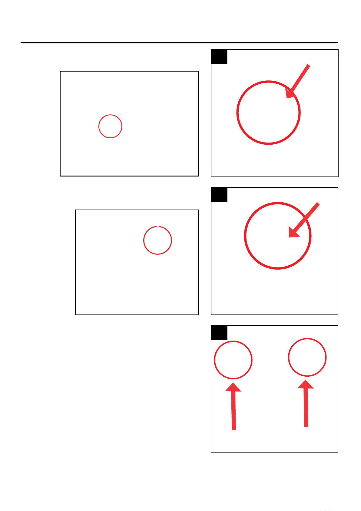
1. Insert and snap lock right metal base support into the
metal base. (Match A to A)
2. Insert and snap lock tombstone base support into the
metal base. (Match B to B)
3. Insert and snap lock the lower support poles into
the metal base. (Match C to C)
1
2
3
Page 3

ASSEMBLY INSTRUCTIONS
4. Insert and snap lock lower support pole with control box
into the metal base. (Match D to D)
5. Snap lock the waist frame to the lower support poles
and lower support pole with control box.
(Match E to E) (Match F to F)
6. Insert and snap lock the upper leg supports to the
waist frame. (Match G to G)
4
5
6
Page 4

ASSEMBLY INSTRUCTIONS
7. Drape the lower fabric over the assembled waist frame,
support poles, and metal base.
Both lower fabric and metal base should be
facing FRONT.
8. Insert the Spine pole into the waist frame. Secure the
spine pole by inserting the LARGE clevis pin through
the hole in the spine pole. Slide the cotter pin through
the hole in the cotter pin to secure and complete the
spine pole assembly.
9. Slide the spine over the spine pole with the red arrow
facing UP and to the BACK of the item.
FRONT
7
8
9
Page 5
FRONT
FRONT
CLEVIS
PIN
COTTER
PIN
BACK

ASSEMBLY INSTRUCTIONS
10. Insert the chest frame into the spine pole. Secure
the chest frame by inserting the LARGE clevis pin
through the hole in the chest frame. Slide the cotter
pin through the hole in the cotter pin to secure and
complete the chest frame assembly. (Match J to J)
10A. To continue assembly, lay the partially assembled
Zombie Groundbreaker against his shipping box as
seen in diagram.
11. Snap lock the rib cage to the chest frame.
(Match K to K) (Match M to M)
and (Match L to L)
10
10A
11
Page 6
CLEVIS
PIN
COTTER
PIN

ASSEMBLY INSTRUCTIONS
12. Place the shoulder frame onto the chest frame.
Insert the shoulder posts into the single and
double post holes.
13. Insert the head into the chest frame. Secure the head
by inserting the LARGE clevis pin through the hole in
the chest frame. Slide the cotter pin through the hole
in the clevis pin to secure and complete the head
assembly. (Match N to N)
12
13
Page 7
SINGLE POST HOLE DOUBLE POST HOLE
CLEVIS
PIN
COTTER
PIN
14. Drape the upper fabric over the shoulder frame.
Attach the hook and loop fasteners under the head,
and on both sides of the rib cage.
14
SIDES OF RIB CAGE UNDER THE HEAD

ASSEMBLY INSTRUCTIONS
16. Attach the left sleeve to the shoulder frame using the
hook and loop fastener. Locate the wire marked W
from the support pole and control box and run it
down the attached LEFT sleeve.
17. Insert and snap lock the left hand with lantern into the
left arm pole. (Match P to P)
Attach the hook and loop on the left sleeve to the
left hand with lantern.
16
17
Page 8
15. Insert and snap lock the left arm into the chest frame.
(Match O to O)
15
W

ASSEMBLY INSTRUCTIONS
18. Insert right hand with sleeve into the chest frame.
(Match Q to Q)
Attach the hook and loop fastener on the right hand
and sleeve to the shoulder frame.
19. Recommended 2 people - Stand item upright on
metal base to proceed to tombstone setup.
Line up the tombstone base with the assembled
metal base.(Match R to R) and (Match S to S)
DO NOT ASSEMBLE. Proceed to the next step.
20. Insert the tombstone post into the tombstone base
marked red. Slide tombstone and tombstone base
towards assembled metal frame. Insert yellow
to yellow.
With the tombstone posts inserted, snap lock
the tombstone frame to the assembled metal frame.
(Match R to R) and (Match S to S)
18
19
20
Page 9
SNAP LOCK TOMBSTONE FRAME
FRONT
R
S

ASSEMBLY INSTRUCTIONS
21. Insert and snap lock the tombstone light to the
tombstone base. (Match U to U)
22. Insert tombstone motor pole into the metal base.
(Match T to T)
23. Snap lock the right hand to the top of the tombstone.
(Match V to V)
21
22
23
Page 10

ASSEMBLY INSTRUCTIONS
24. Connect the wire marked W running down the left
sleeve to the left hand with lantern. (Connect W to W)
25. Connect the wire marked Z1 from the control box to
wire on the tombstone motor pole. (Connect Z1 to Z1)
26. Connect remaining control box wires located under
the upper fabric. (Connect X to X) (Connect Y to Y)
and (Connect Z to Z)
24
25
26
Page 11
W

ASSEMBLY INSTRUCTIONS
27. Secure the tombstone motor pole arm to the
tombstone. Insert the SMALL clevis pin through the
hole in the tombstone motor arm and the support
on the back of the tombstone. Insert the cotter pin
through the clevis pin to secure the motor pole arm.
28. Attach the hook and loop fastener located underneath
the upper fabric to the hook and loop fastener
located on the front of the metal frame.
29. Cover the tombstone motor pole with the tombstone
motor pole cover.
27
28
29
Page 12
FRONT
CLEVIS
PIN
COTTER
PIN

ASSEMBLY INSTRUCTIONS
OPERATING INSTRUCTIONS
30. To secure the Zombie Groundbreaker outdoors, insert
the 4 ground stakes through the corners of the metal
frame and into soft ground.
3030
32. Insert your 5.9V 3A adapter. Fully insert and screw in
until snug. Do not overtighten.
Move the switch to the ON position. Step in front of the
item or make a loud sound (clap) to activate your item.
HUMAN ONLY switch position will activate the item
for one cycle with motion only. (no sound) Move the
switch to the OFF (DEMO) position when the item is
not in use.
3032
FRONT
31. Secure the motor pole and tombstone light cable
to the metal frame with supplied zip tie.
(Match blue to blue)
31
NOTE: Assemble plug
end of adapter by
inserting cord and
sliding collar forward.
Turn collar clockwise
to secure.
Page 13

Page 14
TROUBLESHOOTING
PROBLEM POSSIBLE CAUSE CORRECTIVE ACTION
Item will not
activate.
• 5.9V 3A adapter is not plugged in.
• Switch on control box is not in the
ON position.
• Batteries not inserted or
inserted incorrectly.
• Check 5.9V 3A adapter is plugged in
and securely inserted into the control box.
• Move switch to ON position.
• Install batteries with positive and
negative terminals in the
correct positions.
Item has no sound while
operating. • Volume knob is turned all the way down. • Adjust volume knob to desired volume.
You only hear
item sound but no
item activation.
• Control box wires are not connected • Check that wires labeled W, X, Y, Z and
Z1 are securely connected.
CARE AND MAINTENANCE
• STORE IN A COOL AND DRY ENVIRONMENT.
• IN INCLEMENT WEATHER BRING ITEM INDOORS.
• SURFACE WASHABLE ONLY. DO NOT USE ANY HARSH OR ABRASIVE CLEANING AGENTS.
EXTERNAL SPEAKER IS NOT INCLUDED. MUST BE PURCHASED SEPARATELY.
1. Plug speaker cord into the jack labeled SPEAKER JACK
located on the BASE.
2. Use volume knob on external speaker to control volume levels.
OPTIONAL EXTERNAL SPEAKER SET UP
OPTIONAL DEMO SET UP
1. Insert the cable from optional footpad/push button into the
jack labeled DEMO on the BASE.
2. Place the switch in the DEMO position to enable
DEMO activation.
3. Step on the FOOTPAD or press push button to activate the
scary sequence!
Footpads and push buttons are sold separately and can be
purchased at www.tekkyaccessories.com
*
FOOTPAD/PUSH BUTTON IS NOT INCLUDED. MUST BE PURCHASED SEPARATELY.

FCC REGULATION
Printed in China
Page 15
FCC STATEMENT
FCC RULES: This device complies with Part 15 of the FCC Rules. Operation is subject to the following two
conditions: (1) this device may not cause harmful interference, and (2) this device must accept any interference
received, including interference that may cause undesired operation.
CAUTION: Changes or modications not expressly approved by the party responsible for compliance could void
the user’s authority to operate the equipment.
NOTE: This equipment has been tested and found to comply with the limits for a Class B digital device, pursuant
to Part 15 of the FCC Rules. These limits are designed to provide reasonable protection against harmful
interference in a residential installation. This equipment generates, uses, and can radiate radio frequency energy
and, if not installed and used in accordance with the instructions, may cause harmful interference to radio
communications. However, there is no guarantee that interference will not occur in a particular installation. If this
equipment does cause harmful interference to radio or television reception, which can be determined by turning
the equipment o and on, the user is encouraged to try to correct the interference by one or more of the
following measures:
• Reorient or relocate the receiving antenna.
• Increase the distance between the equipment and receiver.
• Connect the equipment into an outlet on a circuit dierent from that to which the receiver is connected.
• Consult the dealer or an experienced radio/TV technician for help.

ARTÍCULO #5267933
ZOMBI SALIENDO DE
LA TUMBA DE 2,74 M
¿Preguntas, problemas, piezas faltantes? Antes de volver a la tienda, llame a nuestro
Departamento de Servicio al Cliente al 888-251-1006, de lunes a domingo, de 8 a.m. a
8 p.m., hora estándar del Este. También puede ponerse en contacto con nosotros en
MODELO #51200
68606764
HAUNTED LIVING y el diseño del logotipo son marcas comerciales
o marcas registradas de LF, LLC. Todos los derechos reservados.
Página 16

PIEZA DESCRIPCIÓN CANTIDAD
A Base de metal 1
B Varillas de soporte inferiores 2
C Varilla de soporte inferior con caja de control 1
D Soporte de la base de metal derecha 1
E Marco de la cintura 1
F Base de la lápida 1
G Soporte de la base de la lápida 1
H Tela superior 1
I Tela inferior 1
J Soporte de la pierna superior 2
K Varilla de la columna 1
L Varilla del brazo izquierdo 1
M Luz de la lápida/varilla del motor/banda con cremallera 1
N Mano izquierda con farol 1
O Manga izquierda 1
P Mano derecha con manga 1
Q Espinas 1
R Cabeza 1
S Cubierta para varilla del motor de la lápida 1
T Lápida 1
U Marco del pecho 1
U-1 Caja torácica 1
V Marco del hombro 1
W Pasador de chaveta grande y pasadores de horquilla 3
X Pasador de chaveta pequeño y pasador de horquilla 1
Y Estacas para tierra 4
Z Adaptador de 5,9V 3A 1
Z-1 Cinturón de polea de respaldo 3
CONTENIDO DEL PAQUETE
Página 17

Página 18
CONTENIDO DEL PAQUETE
A.
J.
Q. R. S. T. U.
U-1 V. W. X. Y. Z. Z -1
K. L. M. N. O. P.
B. C. D. E. F. G. H. I.
This manual suits for next models
1
Table of contents
Languages:
Other HAUNTED LIVING Home Lighting manuals
Popular Home Lighting manuals by other brands

Safavieh Lighting
Safavieh Lighting TBL4165 manual

Triarch
Triarch Indoor Lighting 32722 Assembly instructions

Masiero
Masiero OLA TL2 installation instructions

BROSA
BROSA Kio Table Lamp Assembly guide

HUDSON VALLEY LIGHTING
HUDSON VALLEY LIGHTING Troy Lighting GARDENA PTL8224 installation instructions

Triarch
Triarch Indoor Lighting 32700/1 Assembly instructions