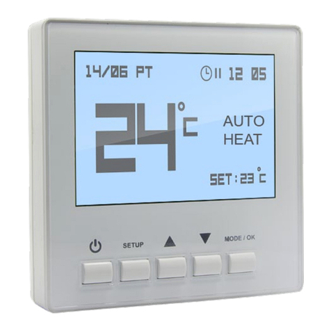
HAVKON INSTRUMENTS FCT.2350.T User manual

Fan Coil Thermostat
User Manual
EN
Thermostats
FCT.2350.T

Doc: 04-11-22, v1.0,r1 www.havkon.com
EN
Warnings
Before using the device, read the user manual
carefully and follow the instructions.
Responsibility for damages, losses and personal
accidents caused by not following the warnings in the
user manual belongs to the user. In this case, the
device is out of warranty in case of malfunctions.
The device must be used in accordance with the
instructions. There should be no electricity in the
connecting cables during assembly. The device must be
protected from moisture, vibration and pollution. Attention
should be paid to the operating temperature.
Shielded and twisted cord cable should be used for input
and output lines that are not connected to the mains.
These cables should not be passed near high power lines
and devices. The shield line must be grounded at the
device side. Installation and electrical connections must
be made by technical personnel in accordance with the
instructions in the user manual.
Before starting the assembly of the device, it should be
visually checked against any damage that may occur
during transportation. Installation and commissioning
must be done by mechanical and electrical technicians.
This responsibility belongs to the buyer.
If there is a danger that may arise from any error or
malfunction on the device, turn off the energy of the
system and disconnect all electrical connections of the
device from the system.
There is no switch on the device to turn off the device's
energy.A switch and fuse must be added to the system by
the user to turn off the energy at the supply input of the
device.
It is necessary to check the supply voltage range of the
device and apply the appropriate supply voltage. This
control process will prevent damage to the device or
system and possible accidents by applying the wrong
supply voltage.
In order to prevent electric shocks and similar accidents,
the device and the installation system should not be
energized before all connections of the device are
completed.
Do not modify or attempt to repair the device.
Interventions on the device may cause malfunction of the
device, damage to the device and the system, electric
shocks and fire.
Never use the device in environments where flammable
and explosive gases are present.
Necessary precautions must be taken regarding all parts
that may pose a danger to the mechanical part where the
device will be mounted. These precautions are necessary
for the safety of the personnel who will do the installation.
The device must be mounted on the system with its own
fixing parts. Do not assemble the device with unsuitable
fixing parts.
In case the device is used for purposes other than
those specified in this user manual, all responsibility
belongs to the user.
The Wattanty period 2 (two) years from the date of
purchase of the device.

Doc: 04-11-22, v1.0,r1 www.havkon.com
EN
1. Fan Coil Thermostat
1.1. FCT.2350.T Series Thermostats
3.2” LCD Display
Manual Fan Operation
Heating/Cooling/Auto Modes
Keylock
5pcs Relay Digital Outputs
Can be integrated into building management
systems via Modbus/RTU (Optional)
Real Time Clock (Optional)
Weekly program

Doc: 04-11-22, v1.0,r1 www.havkon.com
EN
2. Technical Dimensions:
86mm
40mm
86mm

Doc: 04-11-22, v1.0,r1 www.havkon.com
EN
3. Technicial Specifications
Electrical Data
Supply
AC230V ±%10
Power consumption
Max 1VA
Connection
1,5mm² Terminal Connektor
Functions
Fan Relay Outputs
3pcs Digital Relay Output (Max 1A)
Heating/Cooling Relay
Outputs 2pcs Digital Relay Output (Max 1A)
Physical Data
Mounting Type
Wall Mounting
Dimensions
W86XH86xY40mm
Weight
140 Gr
Environmental Data
Operating, Storage
Temperature
0... +40°C/0... +70°C (Without Icing and
Condensation)
Protection Class
IP20 according to EN 60529 standard

Doc: 04-11-22, v1.0,r1 www.havkon.com
EN
4. Functional Features:
Heating, Cooling and Auto Mode
Manual Fan Mode
5 pcs Digital Relay Outputs (Fan Control&Valve Control)
3 Stage Fan Speed Control
Real Time Clock
Weekly Program
Automatic Fan Speed
Can be Integrated in to Building Management Systems Via Modbus/RTU
Configurable User Parameters

Doc: 04-11-22, v1.0,r1 www.havkon.com
EN
5. Room Panel Use
On/Off Button : Manages the ON/OFF functions of the device.
MMode/OK Button : Selects the operating mode of the device (Automatic Heating/Automatic Fan/Manual).
Up Button : Increases Set Temperature
Down Button :Decreases Set Temperature Setting
Fan Button : Changes Fan Level
How to Set Weekly Schedule?
Press the M(MODE/OK) button through the panel for 2 seconds while the device is on.
With the parameter number '0' selected, press the M(MODE/OK) button.
Set the day you want to set with the UP and DOWN buttons and press the M(MODE/OK) button.
When TIMER ON is written, set the start time with the UP and DOWN buttons and press the
M(MODE/OK) button.
When TIMER OFF is written, set the end time with the UP and DOWN buttons and press the
M(MODE/OK) button.
Press ON/OFF button to return to the main screen.
Note1: If the start time is after the end time, the device remains turned off for the selected day.
Note2: If the start time and end time are the same, the weekly schedule application for the selected day will not
work.
Note3: If the device has a weekly schedule setting for the current day, the time logo appears and works on the
screen during scheduled working hours.

Doc: 04-11-22, v1.0,r1 www.havkon.com
EN
How to Set Date and Time?
Press the M(MODE/OK) button through the panel for 2 seconds while the device is on. Point to parameter 1 with
the UP button and press the M(MODE/OK) button.
Select the DAY and MONTH setting with the UP and DOWN button and proceed using the
M(MODE/OK) button.
Select the YEAR setting with the UP and DOWN button and proceed using the M(MODE/OK) button.
Select the TIME and MINUTE setting with the UP and DOWN button and proceed using the
M(MODE/OK) button.
Select the day with the UP and DOWN button and proceed using the M(MODE/OK) button. You can
return to the home screen with the ON/OFF button.
How to Change Device Mode?
You can select manual heating/cooling, automatic heating/cooling or fan mode with the M(MODE/OK) button
when the device is energized.
By pressing the FAN button, you can adjust the fan level or put it in automatic mode.

Doc: 04-11-22, v1.0,r1 www.havkon.com
EN
How to Change Set Temperature?
When the device is on, the device is adjusted in manual or automatic heating or cooling mode with the UP
or DOWN buttons.
How to Turn Off Key Lock On?
The key lock is unlocked by pressing the FAN button for 5 seconds when the device is on.
How to Turn Off Key Lock Off?
The key lock is unlocked by pressing the FAN button for 5 seconds when the device is off.

Doc: 04-11-22, v1.0,r1 www.havkon.com
EN
How to Adjust Screen Brightness?
When the device is on, press the M(MODE/OK) button for 2 seconds.
On the screen that opens, set parameter '2' with the UP or DOWN button and press the
M(MODE/OK) button.
You can adjust the brightness time between 0-10 values with the UP or DOWN buttons on
the screen that opens. 0 minimum 10 maximum.

Doc: 04-11-22, v1.0,r1 www.havkon.com
EN
6. Using The Service Menu
To enter the user service menu:
While the device is off, press the UP and DOWN button for 2 seconds.
Enter the user password on the screen that opens and press the M(MODE/OK) button.
Enter the number of the parameter you want to change on the screen that opens with the UP or DOWN
buttons and press the M(MODE/OK) button.
On the screen that opens, set the appropriate value of the parameter you want to change with the UP
and DOWN buttons and save it by pressing the M(MODE/OK) button.
Note1: Service menu password is 20.
Attention The changes to be made in the Service Setting Menu must be made by the relevant
technical personnel. All responsibility arising from these changes belongs to the person who
changed the device parameter.

Doc: 04-11-22, v1.0,r1 www.havkon.com
EN
FCT.2350.T PARAMETERS LIST V1.0
Par No Description Detail
Factory
Settings
0 Sensor Calibration You can callibrate the room temperature by
pressing up and down buttons. 0
1 System Sellection
You can sellect the right system for your fan
coil system.
0==> 2 Pipe Fan Coil System
1==> 4 Pipe Fan Coil System
1
2 Set Min °C Limiting
Thermostats will off fan and valve at the
same time based on the real limit setup
temperature.
150==> 15.0°C.
150
3 Set Max °C Limiting
Thermostats will off fan and valve at the
same time based on the real limit setup
temperature.
300==> 30°C
350
4 Valve Temperature Diff.(∆T)
The value difference (∆T) between the
temperature set in the valve output
operation of the thermostat and the ambient
temperature can be selected.
10=> 1.0 °C
9
5 Auto Mode. Cooling Range
Settings
Fully automatic mode cooling dead zone
selection
10=> 1.0 °C
5
6 Auto Mode. Heating Range
Settings
Fully automatic mode cooling dead zone
selection
10=> 1.0 °C
5
7 Fan Temperature Diff.(∆T)
The value difference (∆T) between the
temperature set in the fan output operation
of the thermostat and the ambient
temperature can be selected.
10=> 1.0 °C
9
8 Fan Stage Difference Adjustment.
(∆T)
The difference between the fan stages of
the thermostat (∆T) can be selected
10=> 1.0 °C.
10
9 Thermostatic Control
00- Valves and fan stop at the same time
01- Valves Stop but Fan Keeps Running
0
10 Full Auto Mode Fan Stage
You can select the fan step value in full
automatic mode.
00- Valves and Fan Stop at The Same Time
(Default Mode)
01- In full automatic mode, the fan operates
at the 1st stage 02- In the full automatic
mode, the fan operates at the 2nd stage 03-
In the full automatic mode, the fan operates
at the 3rd stage
0

Doc: 04-11-22, v1.0,r1 www.havkon.com
EN
11 Fan/Valve Time You Can Select Fan/Valve Opening and
Clossing Time Settings With This Feature 20
12 Door Contact Function
You can select Temperature location and
Window / Door Contact output with the up
and down buttons.
00- Panel Temp Selection
01- External Temp Selection
02- Panel Temp Selection+Window Contac
2
13 Door Contact NO/NC Selection
You can activate the key card function by
pressing up and down buttons.
00- Key Card Output is Normally Open (NO)
01- Key Card Output is Normally Close (NC)
0
14 Door Contact Delay Time With this Feature, You Can Set The Door
Window Contact Signal Detection Time 20
15 Temperature Sensor Filter Value
You Can Change The Temperature Sensor
Reading Filter Value. If The Filter Value
Increases, The Temperature Value is Read
More Slowly.
5
16 Modbus ID Modbus ID: 1-254 1
17 Modbus Baudrate
0: 1200Bps
1: 2400Bps
2: 4800Bps
3: 9600Bps
4: 19200Bps
3
19 Radiator Mode
00- Radiator Mode Off. Fan+Valve
Operation
01- Radiator Mode On (Valve Operation
Only)
0
20 Valve Relay NO/NC Selection
Relay output selection can be made with the
up or down buttons.
00- Valve Output Normally Open (NO)
01- Valve Output Normally Closed (NC)
0
21 Memory Function
Thanks to this feature, you can choose to
keep all settings the same in case of power
off.
0 - The device continues from where it left
off when it is first energized.
1 - When the device is energized for the first
time, it starts off.
0

Doc: 04-11-22, v1.0,r1 www.havkon.com
EN
7. Schematic
Live (AC230V)
Low Speed Fan
Medium Speed Fan
High Speed Fan
Heating/Cooling Valve
Key Card Connection
Neutral
2 Pipe System Fan Coil Wiring
Neutral
Live (AC230V)
Low Speed Fan
Medium Speed Fan
High Speed Fan
Heating Valve
Cooling Valve
Key Card Connection
4 Pipe System Fan Coil Wiring
Table of contents
Other HAVKON INSTRUMENTS Thermostat manuals
Popular Thermostat manuals by other brands
Contemporary Controls
Contemporary Controls BASstat BAST-321HP-BW2 user manual
Imit
Imit TA3 quick start guide
BASETech
BASETech 1539300 operating instructions
Full Gauge Controls
Full Gauge Controls RT-607RiL power manual

Honeywell
Honeywell WebStat T7351F Application selection and cross-reference guide
Jung
Jung 1790RTR operating instructions
