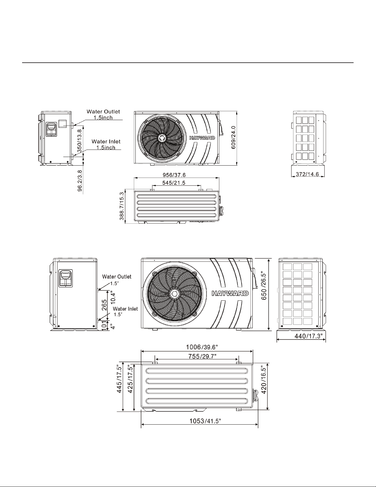
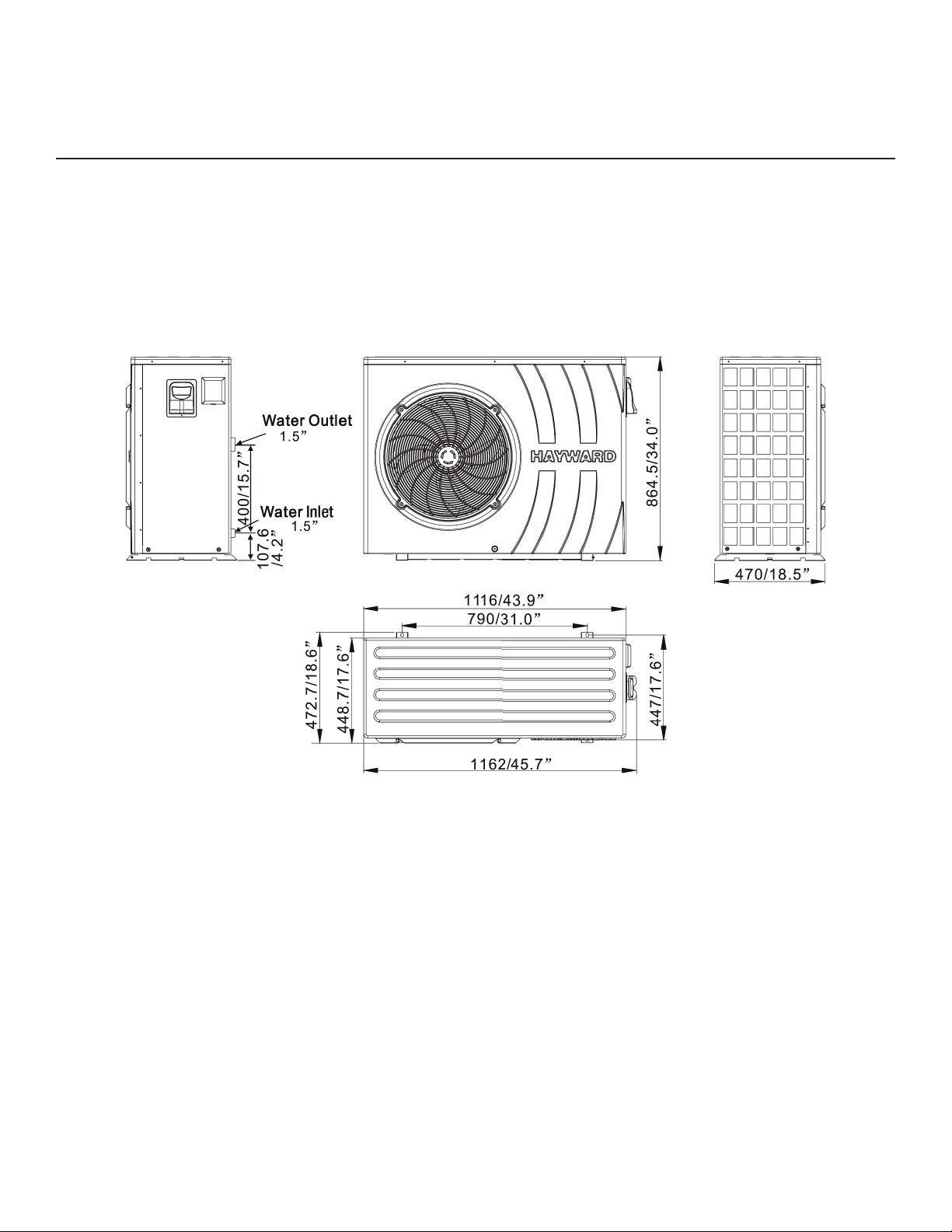
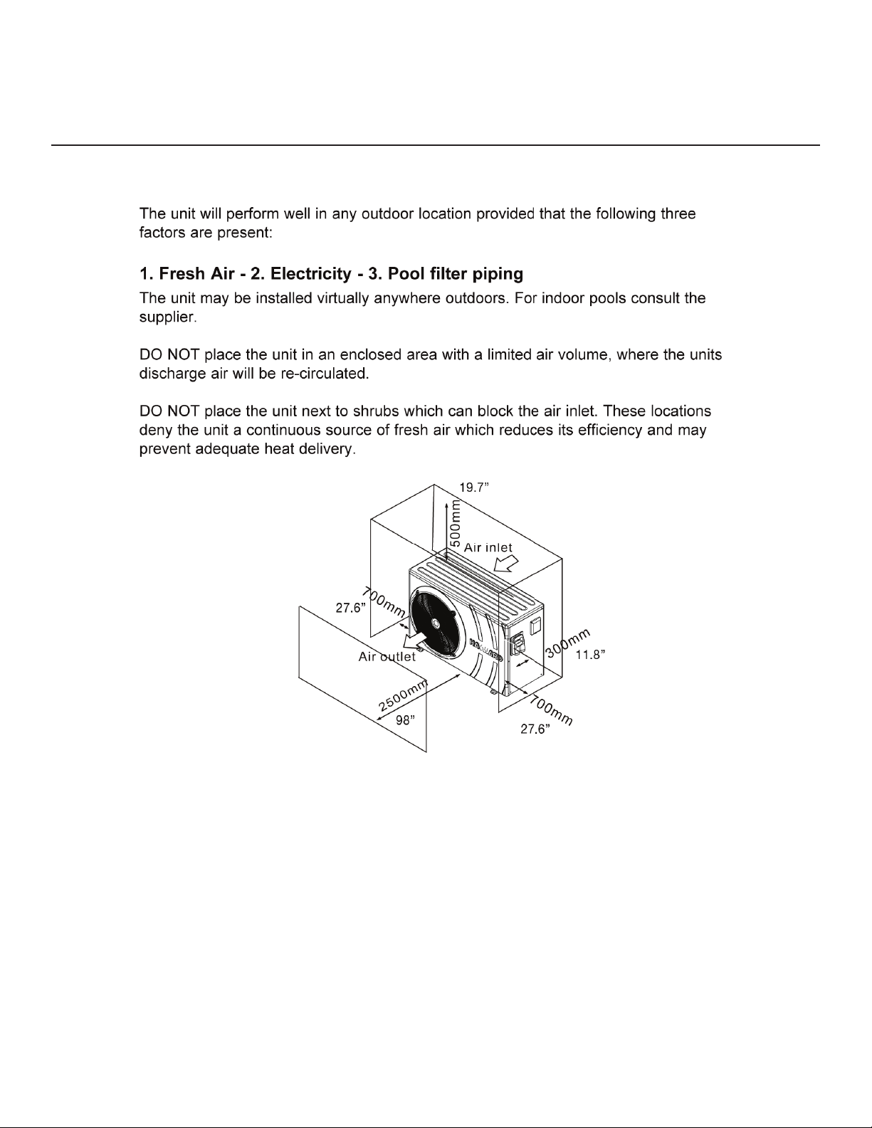
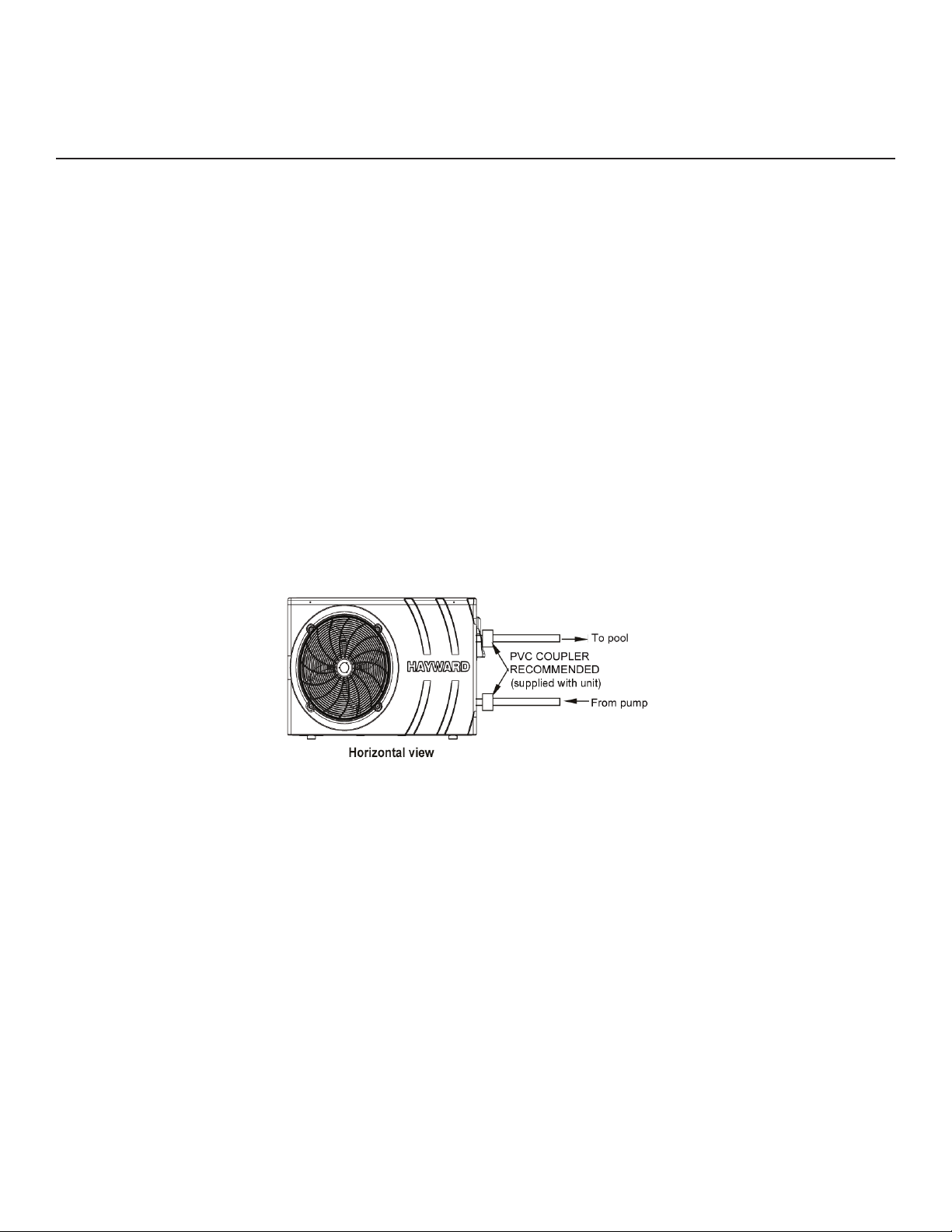
Hayward Pool Products HP40A Service manual

SWIMMING POOL HEAT PUMP UNIT
Installation & Instruction Manual
Models HP40A
HP50A
HP80A
Hayward Pool Products Canada, Inc.
2880 Plymouth Dr., Oakville, ON L6H 5R4
Haywardpool.ca / 1.888.238.7665
REV 2017-1

CONTENTS
1. Preface 1
2. Specifications 2
2.1 Performance Data of Swimming Pool Heat Pump Unit 2
2.2 Dimensions for Swimming Pool Heat Pump Unit 3
3. Installation and Connection 5
3.1 Installation of System 5
3.2 Swimming Pool Heat Pumps: Location 6
3.3 How Close to your Pool? 6
3.4 Swimming Pool Heat Pumps: Plumbing 7
3.5 Swimming Pool Heat Pumps: Electrical Connection 8
3.6 Initial Start-Up of the Unit 8
3.7 Water Flow Setting 9
4. User Interface 10
4.1 Overview 10
4.2 Setting the Clock 12
4.3 Setting the Timer Function 12
4.4 Choice of Operating Mode 13
4.5 Settings and Viewing the Set Point 14
4.6 Locking and Unlocking the Touch Screen 14
4.7 Temperature Display Change 14
4.8 Parameter Table 15
5. Maintenance and Inspection 16
5.1 Maintenance 16
5.2 Troubleshooting Guide 16
5.3 Winterization 17
6. Appendix 18
6.1 Connection of PCB: Illustration 18
6.2 Wiring Diagram 19
6.3 Exploded View and Spare Parts List 22
6.4 Warranty 28

1
1. PREFACE
In order to provide our customers with quality, reliability and versatility, this product has
been made to strict production standards. This manual contains installation, service and
maintenance. Please read this manual carefully before you open or maintain the unit. The
manufacturer of this product will not be held responsible if someone is injured or the unit
is damaged as a result of improper installation, service or unnecessary maintenance. It is
vital that the instructions within this manual are adhered to at all times. The unit must be
installed by qualied personnel.
The unit can only be repaired by qualied installer center personnel or an authorized
dealers (HVAC).
• Maintenance and operation must be carried out according to the recommended time
and frequency, as stated in this manual.
• Use genuine standard spare parts only.
• Failure to comply with these recommendations will invalidate the warranty.
• The Swimming Pool Heat Pump Unit heats the swimming pool water and keeps the
temperature constant.
This type of heat pump has the following characteristics:
1. Durable
The heat exchanger is made of PVC & titanium; the tube can withstand prolonged expo-
sure to corrosives such as chlorine.
2. Quiet operation
The unit contains efcient rotary compressor and a low noise fan motor, which assures
its quiet operation
3. Electronic control board
The unit is controlled by an internal micro-controller, allowing all operation parameters to
be set. Operation status can be displayed on the control panel.

2
2. SPECIFICATIONS
2.1 Performance Data of Swimming Pool Heat Pump Unit
*** REFRIGERANT: R410A
Unit Model HP40A HP50A HP80A
Heating Power Input kW 1.87 2.68 4.2
Running Current A 8.22 12 19
Power Supply V/Hz 208-230V~/60Hz 208-230V~/60Hz 208-230V~/60Hz
Compressor Quantity 1 1 1
Compressor(s) Rotary Rotary Rotary
Fan Quantity 1 1 1
Fan Power Input W 120 120 120
Fan Rotate Speed RPM 850 850 850
Fan Direction Horizontal Horizontal Horizontal
Noise (at 1 meter) dB(A) 54 54 56
Water Connection inch 1.5 1.5 1.5
Water Flow Volume Imperial/US m3/h/gpm 4.0/17 4.5/20 6/26
Water Pressure Drop (max) kPa/psi 12/1.5 10/1.5 12/1.5
Unit Net Dimensions (L/W/H) mm/in 956x372x609 /
37.6x14.6x24
1053x420x650 /
41.5x16.5x25.6
1162x470x865 /
45.7x18.5x34
Unit Shipping Dimensions
(L/W/H) mm 1050x400x615 /
41.4x15.7x24.2
1110x470x670 /
43.7x18.5x26.4
1220x490x880 /
48x19.3x34.6
Net Weight/Shipping Weight kg 54/66 58/71 106/123
Heating: Ambient temp (DB/WB): 80ºF (26.7ºC) / 75.8ºF (24.3ºC)
Water temp (in/out): 80ºF (26.7ºC) / 92ºF (28ºC)

3
2. SPECIFICATIONS
2.2 Dimensions (mm/inches) for the Swimming Pool Heat Pump Unit
Model: HP40A
Model: HP50A

4
2. SPECIFICATIONS
2.2 Dimensions (mm/inches) for the Swimming Pool Heat Pump Unit
Model: HP80A

5
3. INSTALLATION AND CONNECTION
3.1 Installation Illustration

6
3. INSTALLATION AND CONNECTION
3.2 Swimming Pool Heat Pumps: Location
3.3 How Close To Your Pool?
Normally, the pool heat pump is installed within 24.6ft (7.5 metres) of the pool. The longer
the distance from the pool, the greater the heat loss from the piping.

7
3. INSTALLATION AND CONNECTION
3.4 Swimming Pool Heat Pumps: Plumbing
The titanium heat exchanger requires no special plumbing except bypass (please set the ow
rate according to the nameplate). The water pressure drop is less than 1.5psi (10KPa) at maxi-
mum ow rate. Since there are no residual heat or ame temperatures, the unit does not need
copper heat sink piping. PVC pipes can be run straight into the unit.
Location: connect the unit in the pool pump discharge (return) line downstream of all lter and
pool pumps, and upstream of any chlorinators, ozonators or chemical pumps. Install the rubber
feet onto the bottom of the unit.
*You will need to use 1½” male PVC adapter to connect to the heat pump.
Consider adding a quick coupler tting at the unit inlet and outlet to allow easy draining of the
unit for winterizing and to provide easier access should servicing be required (coupler supplied
with unit).
Condensation: since the heat pump cools the air down about 4-5ºC water may condense on
the ns of the horseshoe shaped evaporator. If the relative humidity is
very high, this could be as much as several gallons/litres an hour. Verify the unit is level so that
water will run down the ns into the basepan and drain out through the barbed plastic conden-
sation drain tted on the side of the basepan. This tting is designed to accept 3/4” clear vinyl
tubing and run to a suitable drain. It is easy to mistake the condensation for a water leak inside
the unit.
NB: a quick way to verify that the water is condensation is to shut off the unit and keep the
pool pump running. If the water stops running out of the basepan, it is condensation. An EVEN
QUICKER WAY IS TO TEST THE DRAIN WATER FOR CHLORINE - if there is no chlorine pres-
ent, then it’s condensation.

8
3. INSTALLATION AND CONNECTION
3.5 Swimming Pool Heat Pumps: Electrical Connection
3.6 Initial Start-Up

9
3. INSTALLATION AND CONNECTION
3.7 Water Flow Setting
While the heat pump is running and the water inlet and outlet valves are open, adjust the by-
pass valve to obtain a difference of 2ºC between the water inflow and outflow temperatures (see
Functional Diagram Section 3.1). You can check the setting by viewing the inflow (T02)/outflow
(T03) temperatures directly on the control panel by following the procedure below.
Then adjust the by-pass to obtain a difference of 2ºC between T03 and T02

10
4. USER INTERFACE
4.1 Overview

11
4. USER INTERFACE (continued)
OFF Mode
When the heat pump is on standby (OFF Mode), the time and operating mode
are displayed on the control screen.

12
4. USER INTERFACE (continued)
4.2 Setting the Clock
4.3 Setting the Timer Function

13
4. USER INTERFACE (continued)
4.4 Choice of Operating Mode: Heating, Cooling or Automatic

14
4. USER INTERFACE (continued)
4.5 Settings and viewing the set point (Desired water temperature)
4.6 Locking and unlocking the touch screen
4.7 Temperature Display Change
4.6 Locking and unlocking the touch screen

15
4. USER INTERFACE (continued)
4.8 Parameter Table

16
5. MAINTENANCE AND INSPECTION
5.1 Maintenance
5.2 Troubleshooting Guide
• Check the water supply device and the release often. You should avoid the condition of no water or air entering into
the system as this will influence the unit’s performance and reliability. You should clear the pool/spa filter regularly to
avoid damage to the unit as a result of a clogged filter.
• The area around the unit should be dry, clean and well ventilated. Clean the side heating exchanger regularly to
maintain good heat exchange and conserve energy. Do not pressure wash or use undue force in cleaning as this
may damage fins and reduce efficiency and capacity of heat pump.
• The operation pressure of the refrigerant system should only be serviced by a certified technician.
• Check the power supply and cable connection often. Should the unit begin to operate abnormally, switch it off and
contact your qualified technician.
• Discharge all water in the water pump and water system so that freezing of the water-inlet the pump or water
system does not occur. You should discharge the water at the bottom of the water pump if the unit will not be used
for an extended period of time. You should check the unit thoroughly and fill the system with water fully before
using it for the first time after a prolonged period of no usage.
• Installation must be performed in accordance with the NEC/CEC by authorized person only.

17
5. MAINTENANCE AND INSPECTION
5.3 Winterization

18
6. APPENDIX
6.1 Connection of PCB Illustration
This manual suits for next models
2
Table of contents
Other Hayward Pool Products Swimming Pool Heater manuals
Popular Swimming Pool Heater manuals by other brands

Thermo-Dynamics Boiler
Thermo-Dynamics Boiler THERMOTRON OTF Operation, maintenance, and installation instructions

Raypak
Raypak 131 Service instructions

Amerec
Amerec Pro 12.0 user manual

Celsius
Celsius CELEPANEL operating instructions

Hayward
Hayward H150 Installation, operation and service manual

Argo
Argo Lounge operating instructions

Smith's Heating First
Smith's Heating First PWU 2/3 Installation & user guide

Raypak
Raypak R410A Series Warranty

Raypak
Raypak Versa 155 brochure

Raypak
Raypak 153A GEMINI Illustrate parts list

Sun2Solar
Sun2Solar 805401 Installation and operation manual

Vulcan-Hart
Vulcan-Hart Pool Heater Installation & operating manual