Hazloc Heaters SRH2 User manual

SRH2SRH2SRH2
Steam Rig Heater
CRN: 0H14931.2C
Owner’s Manual, Version: SRH2-OM-B
This manual covers installation, maintenance,
repair, and replacement parts.
Industrial Grade
Heat-Exchanger Unit Heaters
WARNING!
Please adhere to all instructions published in this manual.
Failure to do so may be dangerous and may void your warranty.
The SRH2 heat-exchanger core is covered by the Safety Codes Act and therefore is not field repairable.
Contact factory for a replacement core if fluid leakage occurs.
www.HazlocHeaters.com
Part No. SRH2-OM-B
Printed in Canada
2
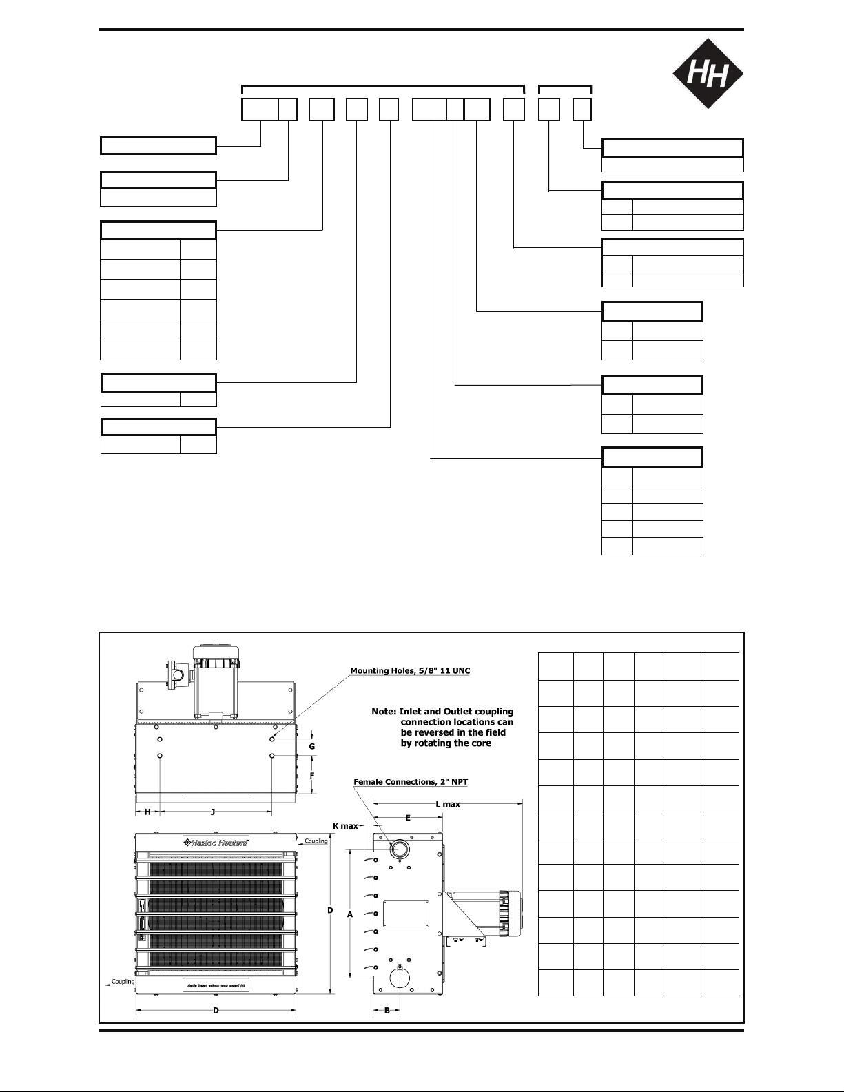
SRH2 Model Coding
SRH2 Physical Dimensions (12 inch to 30 inch models)
Model Code Sequence Required for Ordering
Model Series
Generation
For major revisions
Factory
Assigned
SRH 2 - 12 - C - 1 - 115 1 60 - E - S - A
Product Revision No.
For minor revisions
G General Purpose
Motor Type
E†Explosion proof
50 50 Hertz
Frequency
60 60 Hertz
Phase*
1 1 Phase
3 3 Phase
Motor Voltage*
115 115 Volts
208 208 Volts
230 230 Volts
460 460 Volts
575 575 Volts
#Available in single-pass configuration only due to SafeDeformTM design.
* Other voltages and 3-phase motors available upon request. Longer lead times may
apply. Contact factory.
Motors are designed to be operated at rated voltage with tolerances of ± 10%.
Ensure explosion-proof motors meet the requirements of your hazardous area rating.
†Standard ex-proof motor suitable for Class I & II, Div. 1 & 2, Groups C, D, F & G; T3B.
Approvals
CRN C
Tube Passes
1 Pass#1
12 Inches 12
16 Inches 16
20 Inches 20
24 Inches 24
30 Inches 30
Fan Size
36 Inches 36
S Standard product
Special Items
C Custom product
Heater
Size 16 20 24
Dim. Inches
(mm)
Inches
(mm)
Inches
(mm)
A 15.51
(394)
19.49
(495)
23.46
(596)
B 4.02
(102)
4.02
(102)
4.65
(118)
C 2.38
(60.5)
2.4
(61)
2.4
(61)
D 20.28
(515)
24.29
(617)
28.27
(718)
E 9.76
(248)
10.51
(267)
11.81
(300)
F 5.77
(146.5)
5.75
(146)
6.69
(170)
G 1.75
(44.5)
2.5
(63.5)
2.76
(70)
H 2.64
(67)
3.62
(92)
4.29
(109)
12
Inches
(mm)
12.6
(320)
4.02
(102)
1.85
(47)
16.3
(414)
9.76
(248)
6.77
(172)
(2 holes)
2.64
(67)
30
Inches
(mm)
29.53
(750)
5.71
(145)
2.4
(61)
34.33
(872)
13.78
(350)
7.48
(190)
3.15
(80)
4.37
(111)
J 11.02
(280)
15
(381)
17
(432)
19.69
(500)
25.59
(650)
K 1.38
(35)
1.38
(35)
1.38
(35)
1.38
(35)
1.38
(35)
L 21.65
(550)
21.65
(550)
22.83
(580)
21.21
(615)
27.36
(695)
3
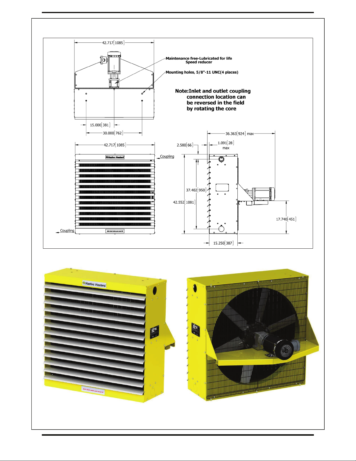
SRH2 Physical Dimensions (36 inch model)
SRH2-36 Front & Rear Views
4
Approvals CRN: 0H14931.2C - steam or fluids (not for use with lethal fluids
as defined by ASME, Section VIII, Div. 1, UW-2).
Maximum Pressure Rating 150 psig (1,034 kPa).
Maximum Design Temperature 550 °F (288°C).
Cabinet Material
14-gauge (0.075 in.) (1.9 mm) steel. SRH2-36 is 12-gauge (0.105
in.)(2.7 mm) steel on top & bottom panels & motor mount. Yellow
epoxy/polyester powder coated with five-stage pretreatment, in-
cluding iron phosphate.
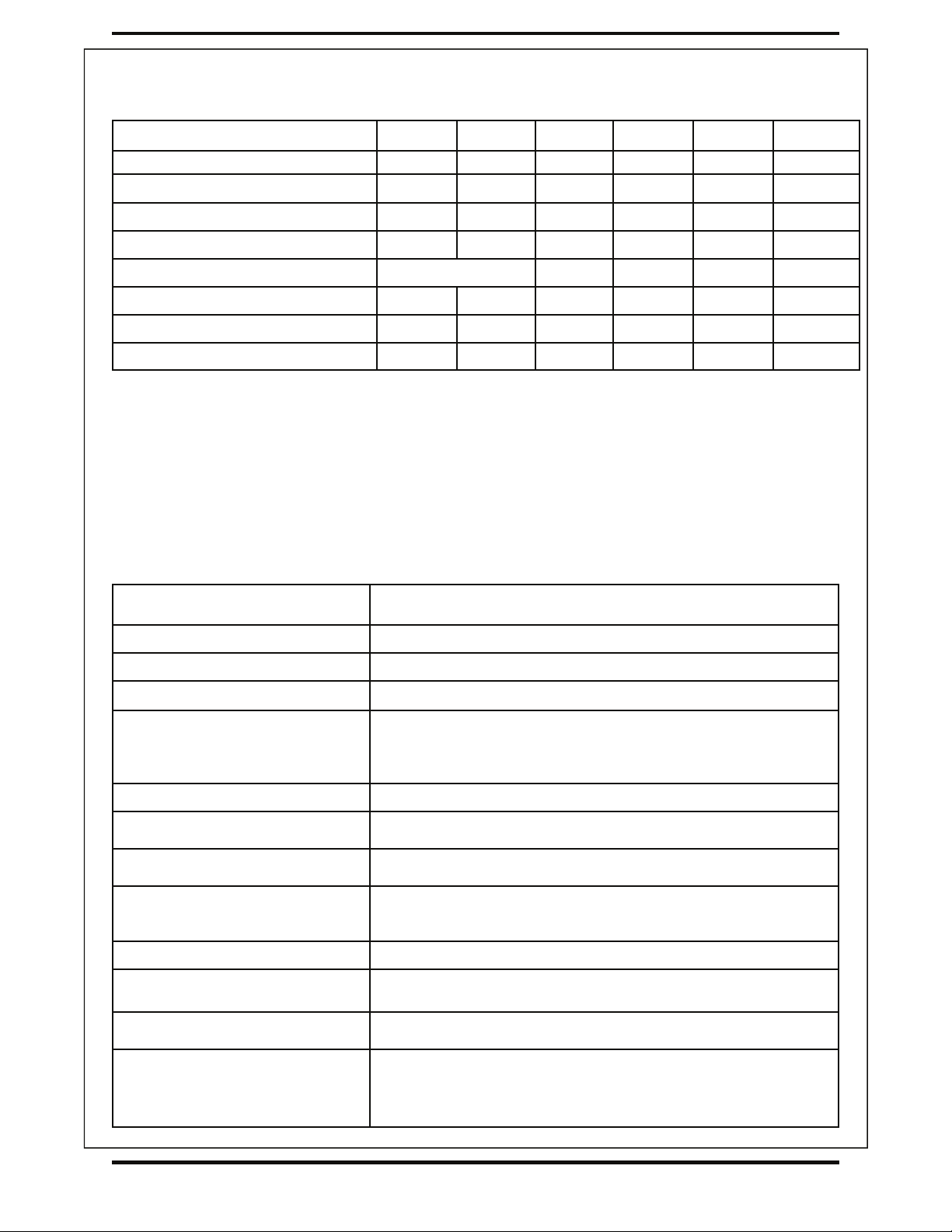
Louver Blades Anodized extruded aluminum.
Fan Spark-proof 3-blade aluminum (SRH2-30 is 2 blade and SRH2-36
is 6 blade).
Fan Guard Split design with close wire spacing. A 3/8 in. (9.5 mm) diameter
probe will not enter.
Motor Drive
Thermally protected CSA or UL Listed 1725 RPM permanently
lubricated ball bearing type with 56 frame. SRH2-36 is a 56C
frame motor and a maintenance-free speed reducer.
Mounting Holes 5/8 in. – 11 UNC – 4 holes at top of heater (2 holes, SRH2-12).
Fluid Connections 2 in. NPT female inlet and outlet (configuration of fluid connection
locations can be reversed by rotating the core).
Header Material 12-gauge (0.105 in.) (2.7 mm) and 3/16 in. (4.8 mm) carbon steel
conforming to ASME requirements.
Finned Tubes
5/8 in. (15.9 mm) outside diameter [16-gauge, 0.065 in. (1.6 mm)
wall thickness] carbon steel tubes with 1-1/2 in. (38.1 mm) outside
diameter copper-free, L-foot, tension-wound aluminum fins @ 10
fins per in.
Minimum Design Metal Temperature -20°F (-29°C).
SRH2 General Specifications
Model SRH2-12 SRH2-16 SRH2-20 SRH2-24 SRH2-30
Fan Diameter in. (mm) 12 (304.8) 16 (406.4) 20 (508.0) 24 (609.6) 30 (762.0)
Air Delivery* CFM (m3/hr) 1090 (1852) 1650 (2803) 3000 (5097) 3800 (6456) 5500 (9344)
Approx. Air Velocity* FPM (m/s) 1305 (6.6) 1111 (5.6) 1309 (6.6) 1138 (5.8) 1066 (5.4)
Air Throw* @ 15 psi steam ft (m) 45 (13.7) 65 (19.8) 70 (21.3) 80(24.4) 85 (25.9)
Motor Power HP (Watts) 1/2 (373) 1/2 (373) 3/4 (559)
Rec. Min. Mounting Height ft (m) 7.5 (2.3) 7.5 (2.3) 7.5 (2.3) 7.5 (2.3) 7.5 (2.3)
Net Weight Lbs (kg) 78 (35.4) 98 (44.4) 132 (59.9) 200 (90.7) 257 (116.6)
Shipping Weight Lbs (kg) 138 (62.6) 158 (71.7) 207 (93.9) 275 (124.7) 332 (150.6)
1/4 (186) or 1/3 (248)
SRH2-36
36 (914.4)
8350 (14186)
928 (4.7)
70 (21.3)
1(746)
7.5 (2.3)
482 (218.6)
594 (269.4)
SRH2 Specifications By Model Size
* At 70°F (21°C), 60 Hz and sea level.

5
— WARNING! —
Read and follow the instructions in this manual. Failure to do so may result in severe or fatal injury.
1. Heater is to be connected and serviced only by qualified personnel experienced in electrical, and piping
work.
2. Installation and wiring of the heater must adhere to all applicable codes.
3. For use with non-lethal fluids only, see ASME Section VIII, Div 1, UW-2.
4. Heater is suitable for maximum operating pressure of 150 psi (1,034 kPa) and maximum operating
temperature of 550°F (288°C). Refer to heater and heat-exchanger data plate.
5. Heater is suitable for use in hazardous locations only if fitted with an approved electric motor and the heat
exchanger fluid temperature is below the ignition temperature of the atmosphere. Ensure installation and
service work is performed by a qualified electrician experienced with hazardous location equipment.
6. Do not operate heater in atmospheres which are corrosive to aluminum or steel, unless it has been coated
with a factory approved protective coating.
7. Heater must be kept clean. When operating in a dirty environment, regularly clean the fin tubes, fan, and fan
guard. Refer to recommended maintenance procedures.
8. Use factory approved replacement parts only.
— INSTALLATION —
These instructions are to be used as a general guideline only.
Location
Please follow guidelines below for optimum heating results:
1. Do not install heaters such that airflow is blocked or impeded by equipment or walls.
2. For occupant comfort, position heaters so that air discharge is directed across areas of highest heat loss,
such as doors, windows, and outside walls.
3. For large areas, arrange heaters such that the air discharge of one heater is directed towards the inlet of the
next heater. This sets up a rotational airflow with air circulation in the central area of the building.
4. For equipment freeze protection, direct air discharge at required equipment.
5. For large workshops or warehouses it may be acceptable to use fewer, but larger heaters.
6. Do not direct air discharge towards a room thermostat.
7. Heater inlet and outlet coupling connection locations can be reversed in the field by removing the core,
rotating it 180 degrees, and then re-installing it. Core-coupling plugs can then be repositioned.
Mounting
1. A variety of mounting brackets are available from the factory to aid in installation.
2. The heater is designed to be installed in an upright and level position. While it may be installed in other
positions, for steam service, the inlet must be above the outlet and the bottom of the heat exchanger must
drain towards the outlet.
3. Heaters are designed to be suspended from the top of the cabinet using either two or four 5/8 – 11 UNC
bolts or threaded rod.
4. It is essential that adequate structural support be provided for installation. The mounting structure must be
strong enough to support the heaters weight, provide sufficient stiffness to prevent excessive vibration, and
withstand all probable abusive situations such as transportable installations where truck off-loading impacts,
etc. may occur.
Mounting Heights and Clearances
1. To ensure that warm air reaches the floor, heaters are usually mounted 7-1/2 ft. (2.3m) to 12 ft. (3.6 m)
above the floor. Heaters may be mounted at higher elevations and still provide warm air at floor level
however, the maximum mounting elevation at which this occurs depends on location and operational
conditions.

6
2. Louvers may be adjusted to provide greater downward deflection of the discharge air. However, it is
recommended that louvers not be set less than 15 degrees from the closed position.
3. Leave at least 22 in. (559 mm) clearance between the rear of the motor and the nearest obstruction.
4. For easy removal of the heat exchanger core assembly, leave clearance beneath the heater equal to the
height of the heater cabinet plus 3 in. (76 mm).
— PIPING SUGGESTIONS —
Suggested piping arrangements only, refer to ASHRAE HVAC Systems & Equipment for more detail
Return Main
Thermostatic Air
Vent option
Petcock (install if trap
does not have air vent)
OR
Hazloc Heaters
Hazloc Heaters
Gate Valve
Steam Main
Union
6" Long
Full Size
Dirt Pocket
Inverted
Bucket Trap
Return Main
Union
Swing
Check
Valve
Gate Valve
15"12"
Gate Valve
Steam Main
Gate Valve
Float &
Thermostatic Trap
Strainer
6" Long
Full Size
Dirt Pocket
10" Min.
Unit Heater Connection for High Pressure Steam
Unit Heater Connection for Low Pressure Steam
- Open Gravity or Vacuum Return System
Note: Heater inlet and outlet coupling
connection locations can be
reversed in the field by rotating
the core.
Corrosion in steam and condensate system piping & unit heaters occurs as a result of the formation of acids within the steam and condensate. The
best defense against corrosion is a boiler water chemical treatment program.
Install heaters using proper piping practices.
Do not use with fluids corrosive to steel.
Use a properly sized steam trap. Inspect traps regularly under your routine maintenance program.
In horizontal pipe runs, use eccentric reducers only.
7
— Piping Practices —
1. Steam unit heaters condense steam rapidly, especially during warm-up periods. The return piping must be
planned to keep the heat-exchanger’s core free of condensate during periods of maximum heat output, and
steam piping must be able to carry a full supply of steam to the unit heater to take the place of condensed
steam. Adequate pipe size is especially important when a unit heater fan is operated under on-off control
because the condensate rate fluctuates rapidly.
2. Heater is to be connected and serviced only by qualified personnel experienced in piping work. For
additional piping information refer to industrial piping handbooks and related literature.
3. Eliminate pipe stress by adequately supporting all piping. Do not rely on heater to support piping.
4. Take off all branch lines from the top of steam mains, preferably at a 45° angle, although vertical 90°
connections are acceptable.
5. Pipe the branch supply line into the steam unit heater’s inlet at the top and the return branch line from the
outlet at the bottom. The heater’s inlet and outlet coupling connections can be reversed in the field
by rotating the heat-exchanger core. Refer to Page 9, Heat-Exchanger Core Assembly Replacement.
6. In steam systems, the branch from the supply main to the heater must pitch down towards the main and be
connected to its top in order to prevent condensate in the main from draining through the heater, where it
might reduce capacity and cause noise. In long branch lines, a drip trap may be needed.
7. Allow for pipe expansion to prevent excessive strain on the unit heater’s heat-exchanger core.
8. The return piping from steam unit heaters should provide a minimum drop of 10 in (254 mm) below the
heater so that the pressure of water required to overcome resistances of check valves, traps, and strainers
will not cause condensate to remain in the heater.
9. In steam systems, where horizontal piping must be reduced in size, use eccentric reducers that permit the
continuance of uniform pitch along the bottom of piping (in downward pitched systems). Avoid using
concentric reducers on horizontal piping, because they can cause water hammer.
10. Installing dirt pockets at the outlet of unit heaters and strainers with 0.063 in. (2 mm) perforations to prevent
rapid plugging are essential to trap dirt and scale that might affect the operation of check valves and traps.
Strainers should always be installed in the steam supply line if the heater is valve controlled.
11. In steam systems, rapid air removal is required because entrained air is a cause of corrosion. Proper air
venting for steam systems can be achieved by use of a steam trap with an internal air vent.
12. Steam traps must be located below the outlet of the unit heater. Consult the trap manufacturer for specific
recommendations. Each steam unit heater should be provided with a trap of sufficient size and capacity to
pass a minimum of twice the normal amount of condensation released by the unit at the minimum differen-
tial pressure in the system. Trap capacity is based on the pressure differential between supply and return
mains. Steam systems should be equipped with a float and thermostatic trap or inverted bucket trap with an
air bypass.
13. If the condensate return line is above the heater outlet or is pressurized, install a check valve after the
steam trap and a drain valve at the strainer to drain the system during the off season.
14. Install pipe unions and shut-off valves at connection points of each unit heater to allow maintenance or
replacement of unit without shutting down and draining the entire system.
15. Adequate air venting is required for low-pressure closed gravity systems. The vertical pipe connection to
the air vent should be at least 3/4 in. NPT to allow water to separate from the air passing to the vent. If
thermostatic instead of float-and-thermostatic traps are used in vacuum systems, a cooling leg must be
installed ahead of the trap.
16. In high-pressure systems, it is customary to continuously vent the air through a petcock unless the steam
trap has a provision for venting air. Most high-pressure return mains terminate in flash tanks that are vent-
ed to the atmosphere. When possible, pressure reducing valves should be installed to permit operation of
the heaters at low pressure. Steam traps must be suitable for the operating pressure encountered.
17. On steam systems where the steam supply to the unit heater is modulated or controlled by a motorized
valve, a vacuum breaker should be installed between the unit outlet and a float and thermostatic trap.
8
— Warning —
Wiring should only be connected by qualified personnel experienced in electrical work.
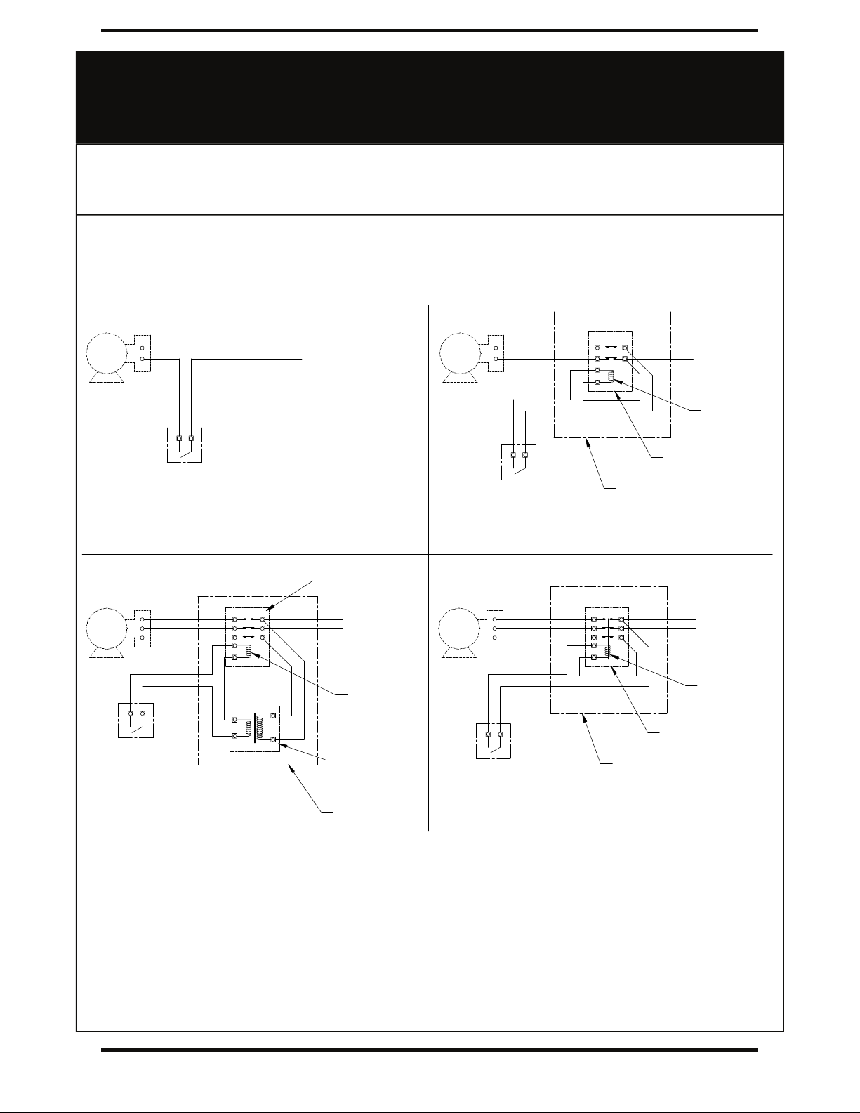
— Electrical Wiring of Motor and Remote Mount Thermostats —
Fan
blade
Motor
Fan
blade
Motor
Fan
blade
Motor
Fan
blade
Motor
Neutral
115 Volt
Thermostat
Supply Voltage
115 Volts,
Single Phase
230 Volt
Thermostat Remote control panel
By customer
2 pole contactor relay
By customer
208/230 Volt
Contactor coil
Supply Voltage
208/230 Volts,
Single Phase
Thermostatic Control for
115 Volts, Single phase motors
Thermostatic Control for
208/230 Volts, Single phase motors
Thermostatic Control for
460/600 Volts, Three phase motors
Thermostatic Control for
208/230 Volts, Three phase motors
Remote control panel
By customer
3 pole contactor relay
By customer
208/230 Volt
Contactor coil
Supply Voltage
208/230 Volts,
Three Phase
Remote control panel
By customer
Voltage Transformer
By customer
24 to 230 Volt
Contactor coil
Supply Voltage
460/600 Volts,
Three Phase
3 pole contactor relay
By customer
24 to 230 Volt
Thermostat
24 to 230 Volt
230 Volt
Thermostat
Motor wiring diagram is located on the motor. On all three-phase heater motors, it is neces-
sary to verify that the fan rotation is correct (counter clockwise when facing the rear of the
heater). If air delivery is not from the front of the heater, reverse any two supply leads in
the motor junction box or the main electrical panel.

9
Heat-Exchanger Core Assembly Replacement
1. Assistance is usually required to remove heat-exchanger core assembly safely.
2. It is not necessary to dismount unit heater from its support structures to remove the heat-exchanger core
assembly. However, it may be advisable in some instances to allow for core assembly removal at ground or
bench level.
3. Remove the bottom heater cabinet cover which is attached with six (6) screws and three (3) bolts.
4. Remove the four bolts on each side of the cabinet while supporting the heat exchanger core assembly.
5. Lower the core assembly from heater.
6. Reverse the procedure to install replacement core and tighten four (4) core bolts to 90 in-lbs torque, bottom
panel screws to 28 in-lbs, and fan panel bolts to 100 in-lbs.
Fan, Fan Guard or Motor Replacement
1. For replacement of fan or fan guard remove four bolts holding motor to the motor mount. For SRH2-36 also
remove speed reducer bolts. If replacing motor only on SRH2-36, only remove motor mounting bolts and
C-face flange bolts.
2. Detach two-piece fan guard assembly by removing top and bottom screws that attach the fan guard to the
cabinet.
3. Remove fan guard pieces through top or bottom. Due to stiffness of fan guards, you may need to remove
two outer top or bottom bolts that attach the fan panel to the top or bottom cabinet panels to provide suffi-
cient clearance.
4. Lift the motor, speed reducer (for SRH2-36 only) and fan assembly off the motor mount.
5. Loosen fan hub screws and remove fan blade from motor shaft.
6. To reassemble, position fan on motor shaft with end of shaft even with face of hub. Ensure the set screw is
faced towards motor and lined up perpendicular to factory-ground flat on motor shaft. This flat is our “Easy-
Off” fan blade replacement feature and only comes on motors purchased from Hazloc Heaters. Tighten set
screw to 150 in-lbs torque.
7. Place motor, speed reducer (for SRH2-36 only) and fan assembly onto motor mount and fasten the two-
piece fan guards to the cabinet.
8. Center fan in fan-shroud opening and leave approximately 1/16” to 3/16” (1.6 to 4.8 mm) gap between
motor face and fan guard.
9. Bolt motor to motor mount, tighten nuts to 250 in-lbs torque. Manually spin the fan blade to ensure it rotates
freely before reconnecting heater to power supply. Fan must rotate counterclockwise when viewed from
rear of heater.
— WARNING! —
Heater should only be service by qualified personnel experienced in electrical and piping work.
Disconnect unit heater from power supply before starting any service or repair work. Lock the disconnect
switch in the “OFF” (open) position and/or tag the switch to prevent unexpected power application.
Failure to follow these procedures may result in severe or fatal injury.
— Repair and Replacement —
Item Torque (in-lbs)
Fan blade set screw 150
5/16 - 18 UNC motor nuts 250
1/4 - 20 UNC core bolts 90
Torque Settings
1/4 - 20 UNC fan panel bolts 100
5/16 - 18 UNC motor mount bolts 250
#10 - 24 UNC bottom panel & louver blade screws 28
1/4 - 20 UNC fan guard self tapping screws 100
Note: Heater inlet and outlet coupling
connection locations can be reversed
in the field by removing the core,
rotating it 180 degrees, and then
re-installing it. Core-coupling plugs
can then be repositioned.
10
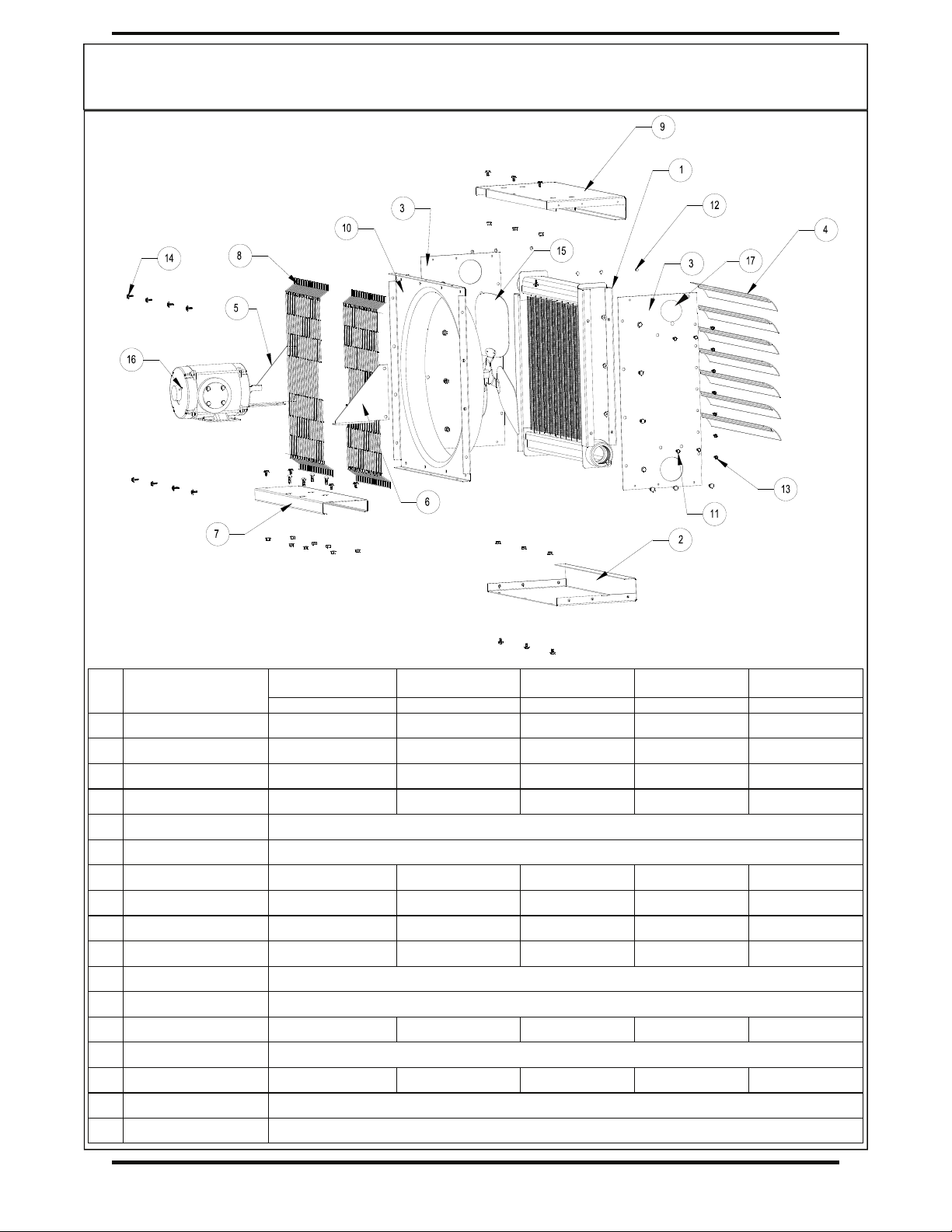
Item
No. Description SRH2-12 SRH2-16 SRH2-20 SRH2-24 SRH2-30
Part Number Part Number Part Number Part Number Part Number
1 Core assembly (1-pass) SRH2-12-10 SRH2-16-10 SRH2-20-10 SRH2-24-10 SRH2-30-10
2 Bottom panel HUH1-12-20-001 HUH1-16-20-001 HUH1-20-20-001 HUH1-24-20-001 HUH1-30-20-001
3 Side panel HUH1-12-20-002 HUH1-16-20-002 HUH1-20-20-002 HUH1-24-20-002 HUH1-30-20-002
4 Louver blade kit HUH1-12-20-003-K HUH1-16-20-003-K HUH1-20-20-003-K HUH1-24-20-003-K HUH1-30-20-003-K
5 Right side motor bracket HUH1-12-20-005
6 Left side motor bracket HUH1-12-20-006
7 Motor base HUH1-12-20-007 HUH1-16-20-007 HUH1-20-20-007 HUH1-24-20-007 HUH1-30-20-007
8 Fan guard (2 pieces) HUH1-12-20-008 HUH1-16-20-008 HUH1-20-20-008 HUH1-24-20-008 HUH1-30-20-008
9 Top panel HUH1-12-21 HUH1-16-21 HUH1-20-21 HUH1-24-21 HUH1-30-21
10 Fan panel HUH1-12-22 HUH1-16-22 HUH1-20-22 HUH1-24-22 HUH1-30-22
11 Core screw kit HUH-CM-SK
12 POP rivet, 3/16” kit HH-TP-RK
13 Louver screw kit HUH1-12-LB-SK HUH1-16-LB-SK HUH1-20-LB-SK HUH1-24-LB-SK
14 Fan guard screw kit HH-FG-SK
15 Fan blade HUH1-12-FB HUH1-16-FB HUH1-20-FB HUH1-24-FB HUH1-30-FB
16 Motor Specify motor voltage, phase, frequency, horsepower and type of enclosure (general purpose or explosion-proof)
17 Coupling-hole plug HUH1-001
HUH1-30-LB-SK
— Parts List —
*** Please have heater model & serial number available before calling ***
Note: Inlet and outlet coupling
connection locations can
be reversed in the field
by rotating the core.
SRH2 (12 inch to 30 inch models)
11
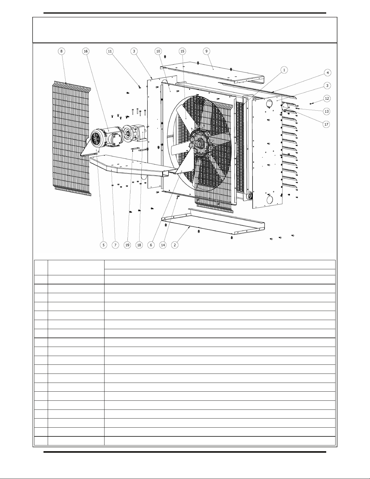
Item
No. Description SRH2-36
Part Number
1 Core assembly (1-pass) SRH2-36-10
2 Bottom panel HUH2-36-20-001
3 Side panel HUH2-36-20-002
4 Louver blade kit HUH2-36-20-003-K
5 Right side motor bracket HUH2-36-20-005
6 Left side motor bracket HUH2-36-20-006
7 Motor base HUH2-36-20-007
8 Fan guard (2 pieces) HUH2-36-20-008
9 Top panel HUH2-36-21
10 Fan panel HUH2-36-22
11 Core screw kit HUH-CM-SK
12 POP rivet, 3/16” kit HH-TP-RK
13 Louver screw kit HUH2-36-LB-SK
14 Fan guard screw kit HH-FG-SK
15 Fan blade HUH2-36-FB
16 Motor Specify motor voltage, phase, frequency, horsepower and type of enclosure (general purpose or explosion-proof)
17 Coupling-hole plug HUH1-001
18 Speed Reducer HUH2-36-SD
19 Speed reducer shim HUH2-36-20-010
— Parts List —
*** Please have heater model & serial number available before calling ***
Note: Inlet and outlet coupling
connection locations can
be reversed in the field
by rotating the core.
SRH2 (36 inch model)
12
Regular inspection, based on a schedule determined by the amount of dirt in the atmosphere, assures
maximum operating economy and heating capacity.
Annual Inspection (before each heating season)
1. Check all terminal connections and electrical conductors for damage, looseness, defects, fraying, etc. and
replace or tighten where applicable.
2. Check for fluid leakage from heat-exchanger core. If fluid leakage occurs, remove heater from service and
have the heat-exchanger core replaced by a factory replacement unit. Refer to “Repair and Replacement”
section for complete details. Note: This heat-exchanger core is covered by the Safety Codes Act and
therefore is not field repairable.
3. Check electrical junction box. Inside of enclosure must be clean, dry, and free from any foreign materials.
The cover must also be completely on and tight.
4. Check motor shaft bearing play. Replace motor if play is excessive or if motor does not run quietly and
smoothly. Motor bearings are permanently lubricated.
5. On SRH2-36 models, speed reducer is maintenance free. Check for excessive noise and vibration.
6. Check fan. Replace immediately if cracked or damaged.
7. Check louvers. Louver screws should be tight. Louvers are not to be set less than 15 degrees of the closed
position.
8. Check the tightness of all hardware. All nuts and bolts, including mounting hardware, must be tightened to
torque settings on Page 9.
9. Turn heater motor on for a minimum of 10 minutes. Check for air exiting heater through louvers and smooth
running of motor.
10. Ensure periodic cleaning of complete heater is done
Periodic Maintenance (before and as required during heating season)
1. Clean the following (remove dust using compressed air):
Finned tubes
Fan
Fan Guard
Motor
Louvers
Cabinet
2. Check the following:
Motor (and speed reducer on SRH2-36) for smooth and quiet operation
Louvers for proper angle and tightness
Electrical junction box covers are secure
— WARNING! —
Heater should only be service by qualified personnel experienced in electrical and piping work.
Disconnect unit heater from power supply before starting any service or repair work. Lock the disconnect
switch in the “OFF” (open) position and/or tag the switch to prevent unexpected power application.
Failure to follow these procedures may result in severe or fatal injury.
— Maintenance Program —
13
HEATER MAINTENANCE RECORD
Heater Model: _________________________ Serial No.: ______________________________
Date of
Maintenance
Performed
By Maintenance Performed

14
NOTES

15
NOTES
PRINTED IN CANADA
©Copyright 2015
The information contained in this
manual has been carefully checked
and verified for accuracy. Specifica-
tions subject to change without
notice.
Hazloc Heaters is a trademark of
Hazloc Heaters Inc.
#1, 666 Goddard Ave. NE
Calgary, Alberta T2K 5X3
Canada
Tel.: +1-403-730-2488
Fax: +1-403-730-2482
Customer Toll Free (U.S. & Canada):
+1-866-701-Heat (4328)
www.HazlocHeaters.com
Limited 18-Month Warranty
Hazloc HeatersTM warrants all SRH2 series of heat-exchanger unit
heaters against defects in materials and workmanship under normal
conditions of use for a period of eighteen (18) months from date of
purchase based on the following terms:
1. The heater must not be modified in any way.
2. The heater must be stored, installed and used only in accordance with
the owner’s manual and attached data plate information.
3. Replacement parts will be provided free of charge as necessary to
restore any unit to normal operating condition, provided that the
defective parts be returned to us freight prepaid and that the
replacement parts be accepted freight collect.
4. The complete heater may be returned to our manufacturing plant for
repair or replacement (at our discretion), freight charges prepaid.
5. Components damaged by contamination from dirt, dust, etc. or
corrosion will not be considered as defects.
6. This warranty shall be limited to the actual equipment involved and,
under no circumstances, shall include or extend to installation or
removal costs, or to consequential damages or losses.
Table of contents
Other Hazloc Heaters Heater manuals

Popular Heater manuals by other brands


flowair
flowair LEO FB 10 Operation manual

Pentair
Pentair ETi 400 installation guide

Goldair
Goldair GBH100 operating instructions

Arcotherm
Arcotherm EC 200 Service manual

Superior Radiant
Superior Radiant eWAVE Series Installation, operation and service instructions

Dimplex
Dimplex XLE Series quick start guide


