3
CONTROL SYSTEM
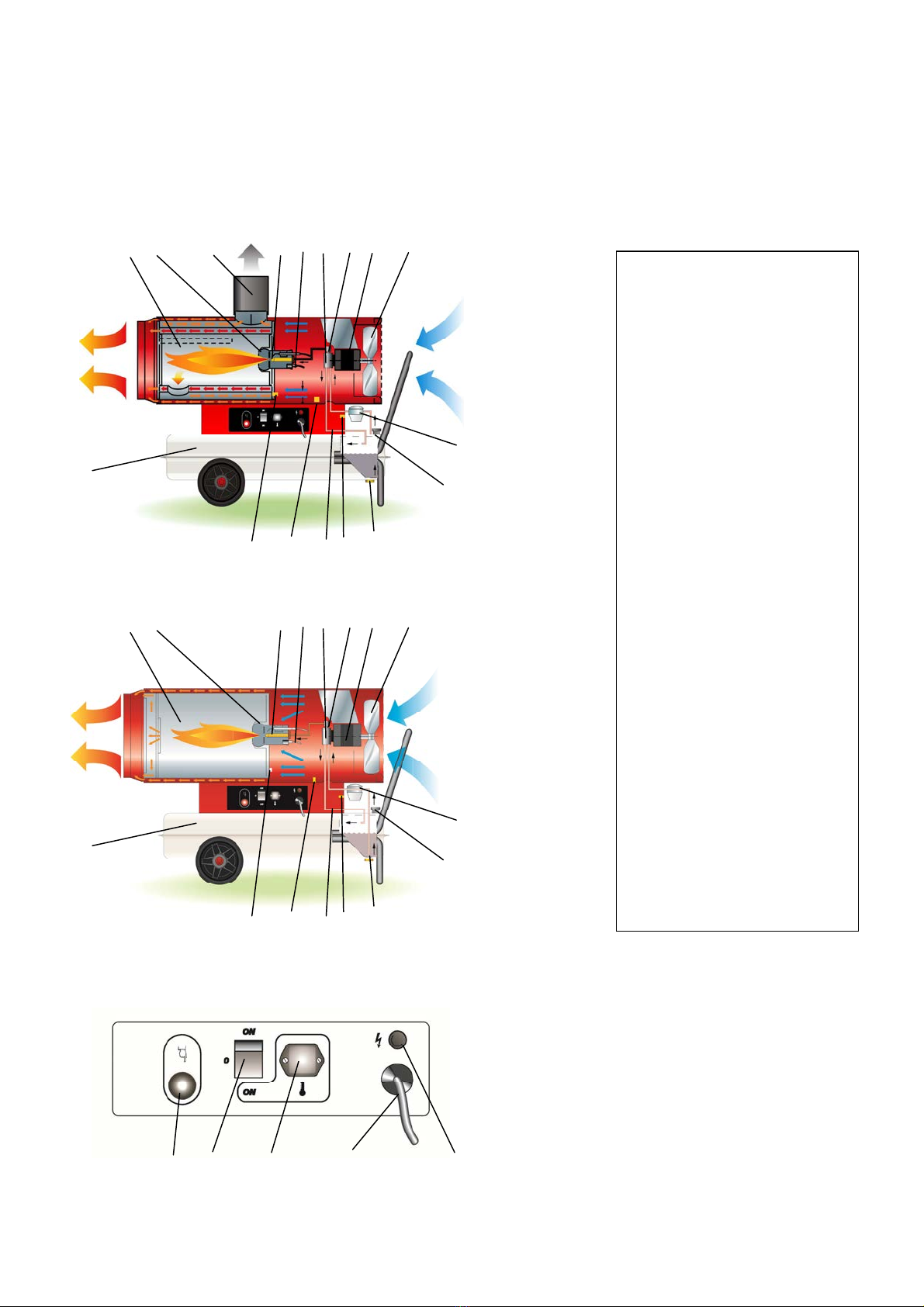
The heater has all operational controls located in a watertight control panel mounted on the lateral side of the unit.
The control panel consists of:
•a 3-position switch for heating function: normal operation, stop or thermostat operation
•plug to connect a remote room thermostat
•power cord
•high voltage transformer that generates a spark to ignite the flame
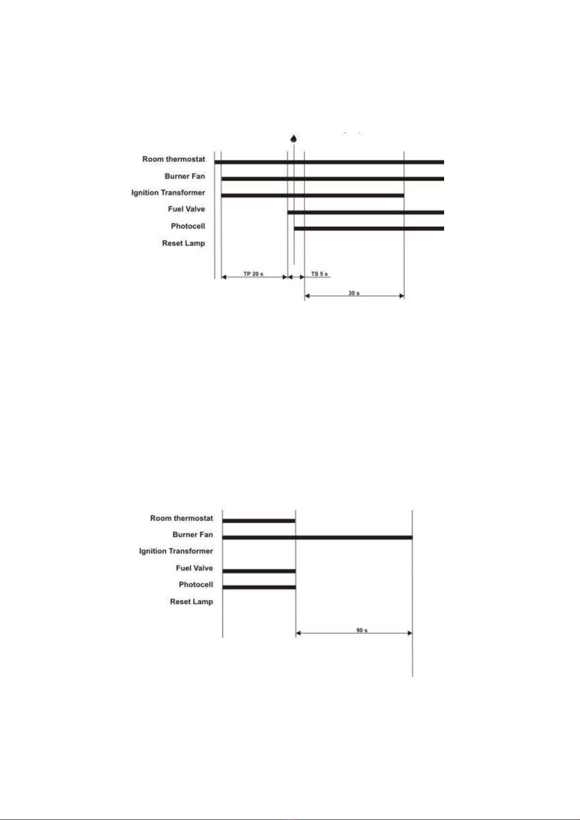
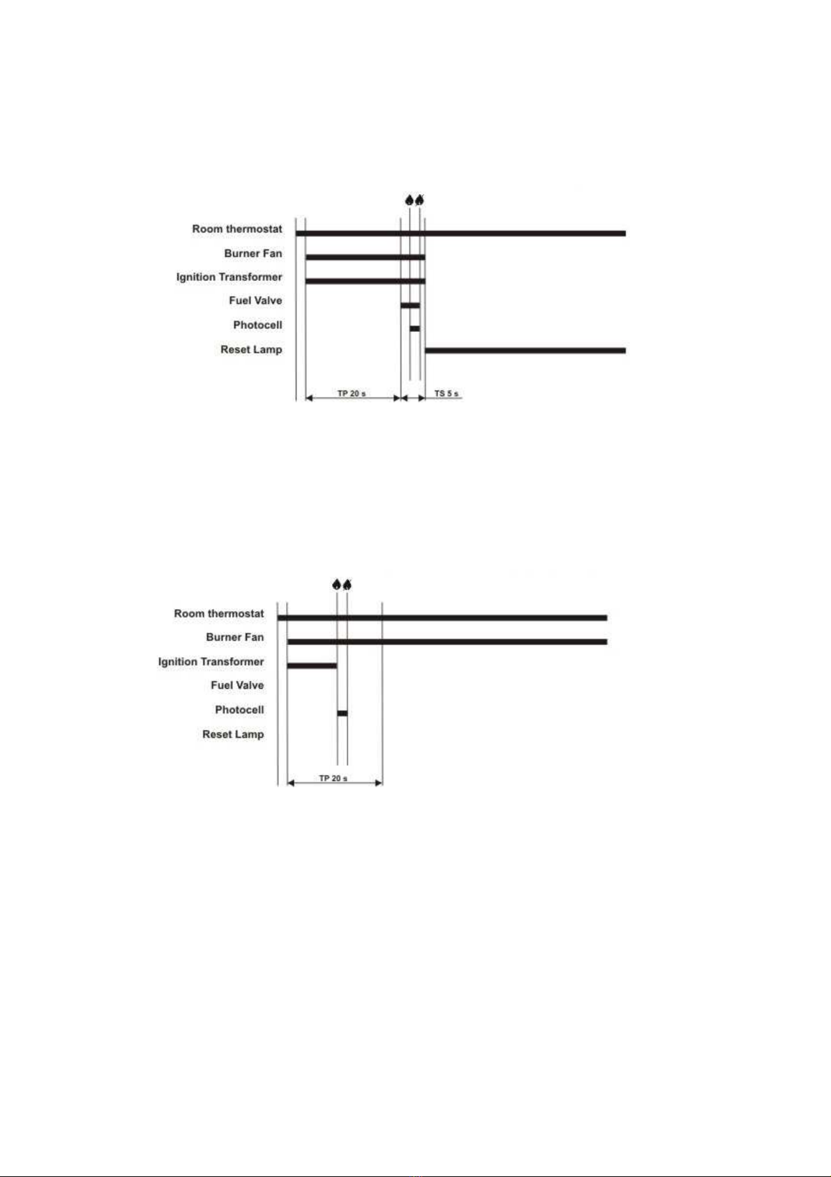
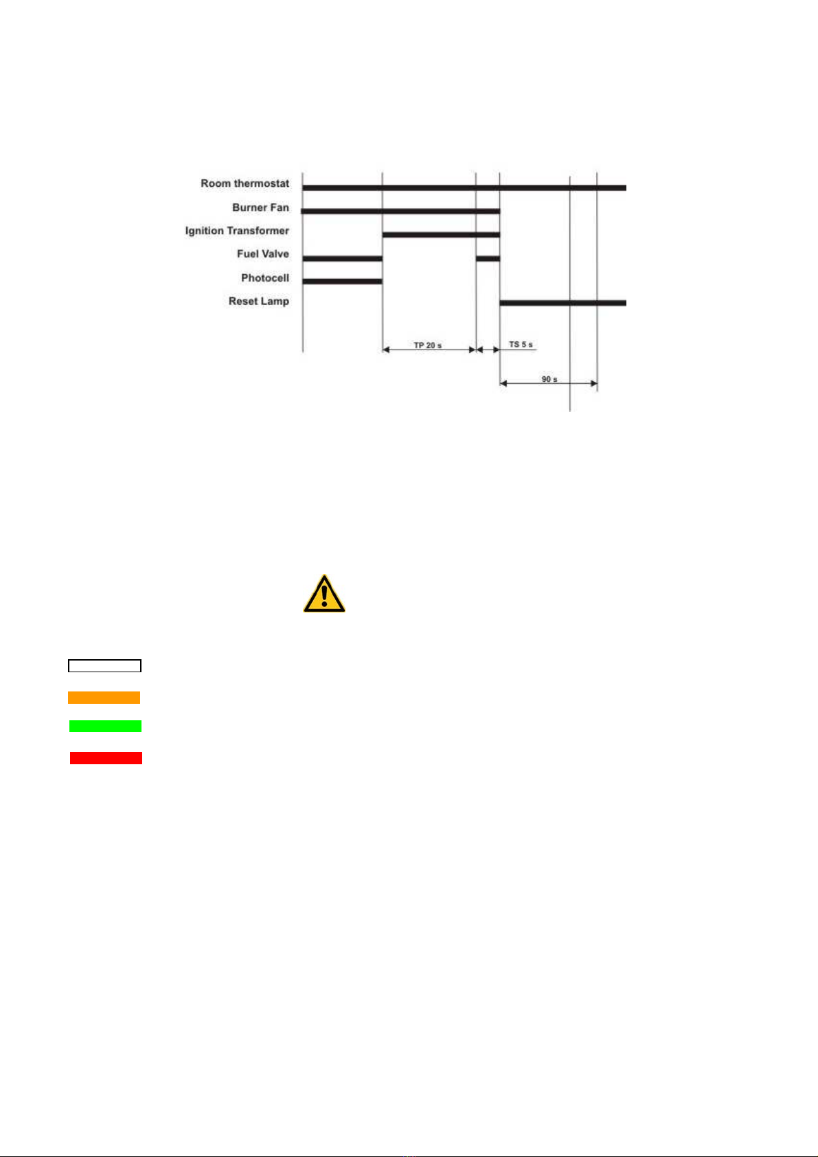
•control flame box to handle starting / running cycle (see paragraph 2.).
The control flame box is equipped with a reset
The control system utilizes:
•a safety shut off switch that is a overheat thermostat shutting down the unit if the temperature of combustion
chamber and outlet air exceed the maximum allowed level
•an air pressure switch, that stops the unit if the air flow is not sufficient for combustion.
•a flame detector, that is a photocell monitoring constantly the flame presence and its integrity.
•a pair of ignition rods to create the ignition spark
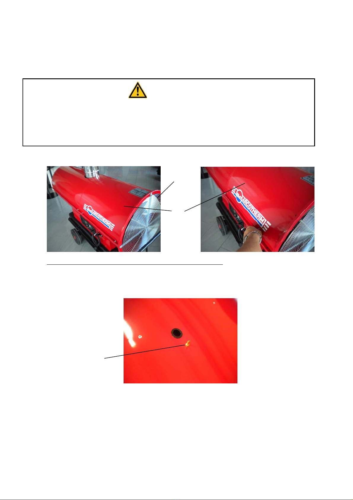
FUEL SYSTEM
The fuel system consists of:
•fuel tank, that is steel, corrosion proof
The fuel tank hase a drain plug located underneath it to allow discharge of residual fuel before cleaning.
•fuel filter
•fuel pump. A screw fitted on the fuel pump allows the adjustment of fuel pressure setting
•fuel ON/OFF solenoid valve
oduring normal operation the valve is open and the pressurized fuel flows to the nozzle, where it is
atomized, mixed with primary combustion air and ignited by the electrode spark
oduring abnormal operation (see paragraph 2.) the flame control unit closes the fuel solenoid valve and
the unit stops.
•fuel circuit, including suction and return hoses from fuel tank to fuel pump and high pressure microhose from
fuel pump to nozzle
•burner head
•nozzle
COMBUSTION CHAMBER
For indirect heater it consists of:
•the internal combustion chamber (stainless steel made) that containing the flames and
•the external high efficient heat exchanger (aluminated steel made), that leads smokes to chimney / stack.
For direct heater it consists of the internal combustion chamber (stainless steel made) that containing the flames and
exhanges heat with the main airflow stream.
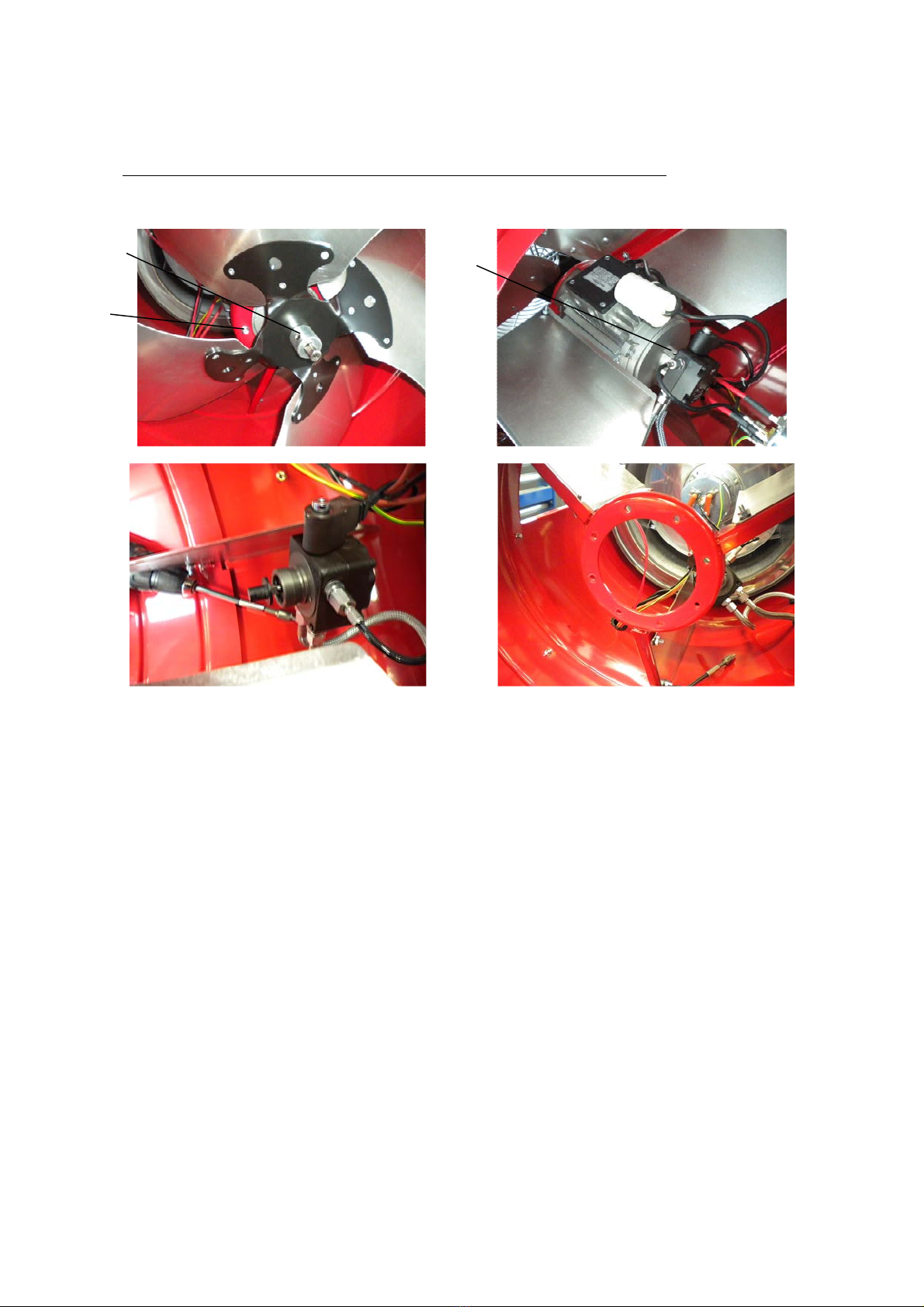
BURNER HEAD
The burner head is the assembly that determines the correct mixing of combustion air and fuel inside the combustion
chamber and it consists of:
•Fuel nozzle
•Nozzle support
•Flame diffuser
•Air opening baffle: a screw fitted on the burner head allows the adjustment of combustion air setting
•Ignition electrodes
•Flame detector
FAN – MOTOR ASSEMBLY
The electric motor drives the fuel pump assembly and a fan which blows air inside and around combustion chamber.