HB-THERM M8095-EN User manual

Temperatur Control Technology
www.hb-therm.ch
M8095-EN 2020-09 1/13
2020-09
Page
Assembly Instructions
M8095-EN
Spare part unit board GIF-51 (O/ID T25240-X, T27401-X)
Contents
Purpose...........................................................................................2
Precondition...................................................................................2
Procedure .......................................................................................2
Product group Thermo-5...............................................................3
Product group Treat-5 and Clean-5............................................10
Parts list........................................................................................13
Assembly Instructions M8095-EN
M8095-EN 2020-09 2/13
Purpose
Replacement of control unit board GIF-51 (A 4)
Precondition
WARNING!
Danger for unauthorized persons!
Conversion work may only be carried out by
specialist staff who have been trained accordingly.
Therefore:
–Keep unauthorized persons away from the work
area.
NOTE!
Knowledge of the Instruction Manual is a
precondition for carrying out conversion work on
the unit.
Procedure
DANGER!
Danger to life caused by electric current!
Touching conductive parts causes a direct danger
to life.
Therefore:
–For all work on the electrical system, for
maintenance, cleaning or repair work,
disconnect from the mains or disconnect all
phases of the external power supply and secure
them against being switched on again. Check
unit is isolated from power supply.
WARNING!
Danger of crushing due to rolling away or
tipping
With an uneven floor or when the castors are not
locked, there is a danger that the unit tips over or
rolls away causing crushing.
Therefore:
–Only install the unit on an even floor.
–Ensure that the castors are locked.

Assembly Instructions M8095-EN
M8095-EN 2020-09 3/13
Product group Thermo-5
1. Switch off master switch and disconnect from mains supply.
2. Loosen the screws in the front panel and hinge it down.
3. Proceed as follows in order to remove the GIF-51 (A 4):
Remove all connectors.
Remove the flexes that are led through current transformers
(TA 1.1, 1.2, 1.3) at the contactor or terminal:
Cable routing
(from to)
Unit type
KM 1
X 86
Housing size 1+2, 8 kW, 400/460 V
KM 1
XT 2
Housing size 1, 8 kW, 210 V
KM 1
XT 2
Housing size 2, 16 kW, 400/460 V
XT 2
V x.x
Housing size 2, 8+16 kW, 210 V
KM 1
FS 4
Housing size 3, Pump type G_, L_, 6_, 8_
Remove the screws on the sides of the board.
On oil unit unplug the printed circuit board level measuring
(A 10).
Fig. 1: Cable routing
Fig. 2: Cable routing housing size 3 pump
G_, L_, 6_, 8_
4. Proceed as follows in order to fit the new GIF-51 (A4):
On oil unit insert the printed circuit board level measuring (A 10)
into new GIF-51.
Fit the GIF-51 and fix with the screws.
Route the wires through current transformers (TA 1.1, 1.2, 1.3)
and connect them (Fig. 1).
Cable routing
(from to)
Unit type
KM 1
X 86
Housing size 1+2, 8 kW, 400/460 V
KM 1
XT 2
Housing size 1, 8 kW, 210 V
KM 1
XT 2
Housing size 2, 16 kW, 400/460 V
XT 2
V x.x
Housing size 2, 8+16 kW, 210 V
KM 1
FS 4
Housing size 3, Pump type G_, L_, 6_, 8_
For housing size 3, pump type G_, L_, 6_, 8_ additionally lead
wires from cable connector (X 63) through current transformer
(TA 1.2) and connect to contactor KM 4/A1, KM 5/A1 (Fig. 2).
Connect all connectors.
Connect main pump cable (X 62/X 64):
Voltage 200–220 V Slot X 62 (triangle)
Voltage 380–480 V Slot X 64 (star)
A 10
fromto
X 62
X 64
TA 1.3
TA 1.2
TA 1.1
KM 4/KM 5
X 63
TA 1.2
Assembly Instructions M8095-EN
M8095-EN 2020-09 4/13
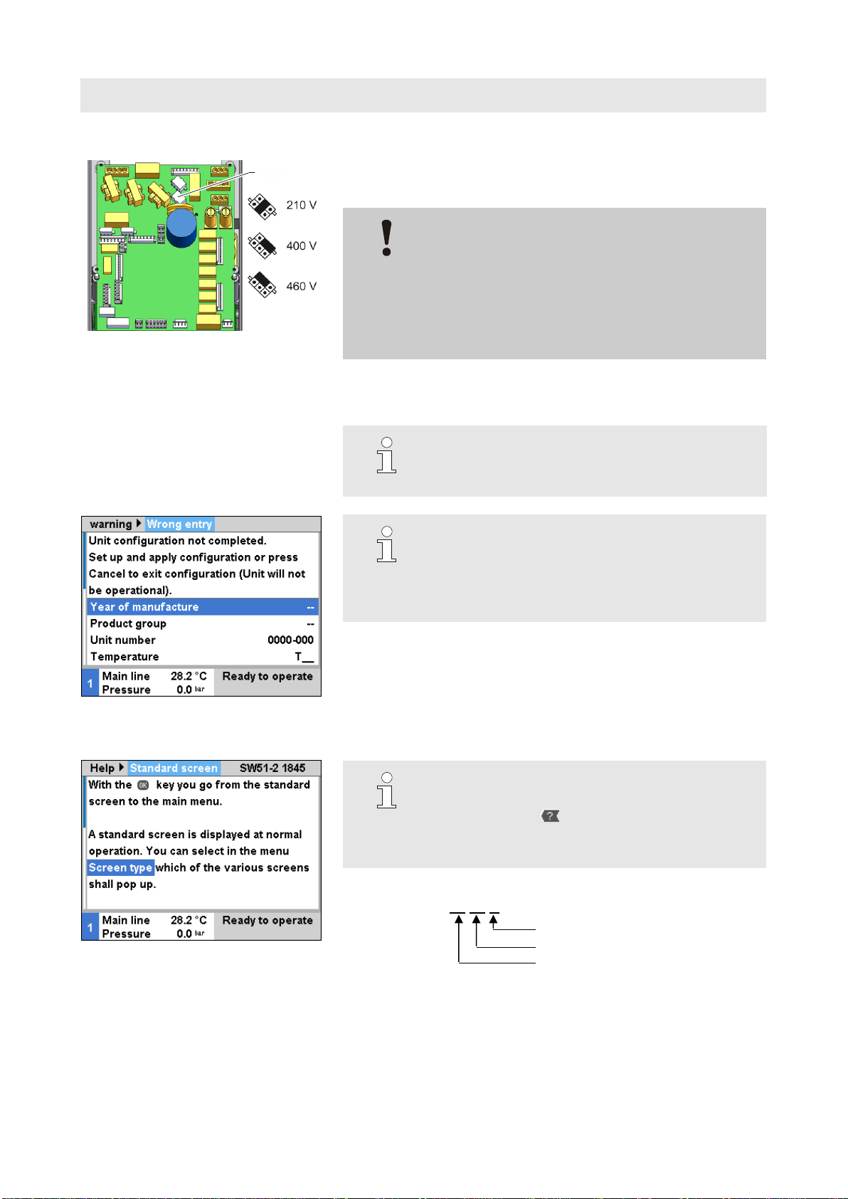
Fig. 3: Voltage selection GIF-51
5. Voltage selection at X 15 with bridge plug (O/ID T21608):
Verify mains voltage (specification on the nameplate)
Place bridge according (Fig. 3)
ATTENTION!
Danger if wrongly connected
Wrong voltage selection or wrong connections can
damage the unit
Therefore:
–Thoroughly check connections and voltage
selection
6. Close and secure the front panel.
7. Reconnect mains plug and switch on main switch.
NOTE!
The unit will maybe perform an automatic software
update.
Fig. 4: Input window configuration
NOTICE!
If configuration is incomplete, the warning text
"Wrong entry" will be displayed. By cancelling the
configuration, the user can exit configuration mode
and subsequently conduct a Reset complete.
Fig. 5: Software version display
8. Checking the software version
NOTICE!
You can verify the currently installed software
version using the button on the basic screen.
The software version is indicated in the top right
corner (
Fig. 5).
Software version designation:
Ex. SW51-2 18 45 A
Index (optional)
Calendar week
Year
X 15

Assembly Instructions M8095-EN
M8095-EN 2020-09 5/13
Fig. 6: Reset complete
9. Carrying out a Complete reset
(Software version prior to SW51-1 0849B)
Service \ Support using "Support" user profile
(From software version SW51-1 0849B onwards)
Service \ Configuration using "Support" user profile
NOTICE!
From software version SW51-1 0916 onwards, the
Service \ Configuration menu is accessed using the
code 1?2?.
Fig. 7: Configuration
10.Configure unit
(to Software Version SW51-2 1431)
Service \ Configuration menu using the “Support” user profile.
NOTICE!
When configuring note the following:
- Select product group according to table below
- Check data on the nameplate
- Read appendix of Operating Manual
(for special versions)
Product group
Product type
TG
Thermo-5 temperature control unit
TR
Treat-5 water treatment unit
CL
Clean-5 cleaning unit
Fig. 8: Input window configuration
(from Software Version SW51-2 1449)
NOTICE!
As of software SW51-2 1449, the configuration is
requested after power ON automatically via the
input window (
Fig. 8).

Assembly Instructions M8095-EN
M8095-EN 2020-09 6/13
Fig. 9: Configuration special devices
Additionally with special devices
Parameter Special device type OEM and Special device OEM
version under Service / Configuration as stated on rating plate.
Exa. device type HB160ZM1LE1
OEM version
OEM type
11.Check that the unit is free of pressure
(Pressure gauge rear of unit).
12.Calibrating the unit
NOTICE!
A quality check can be carried out if required.
During the automatic check, the most important
measurements of the temperature control unit can
be compared. Points 13–18 are omitted when the
automatic check is carried out.
Requirement:
Software version >SW51-2_1540 is installed.
Checking device HB-TP180/200 for heating unit, proceed
according to the operating instructions for HB-TP180/200
(O8354-X).
Assembly Instructions M8095-EN
M8095-EN 2020-09 7/13
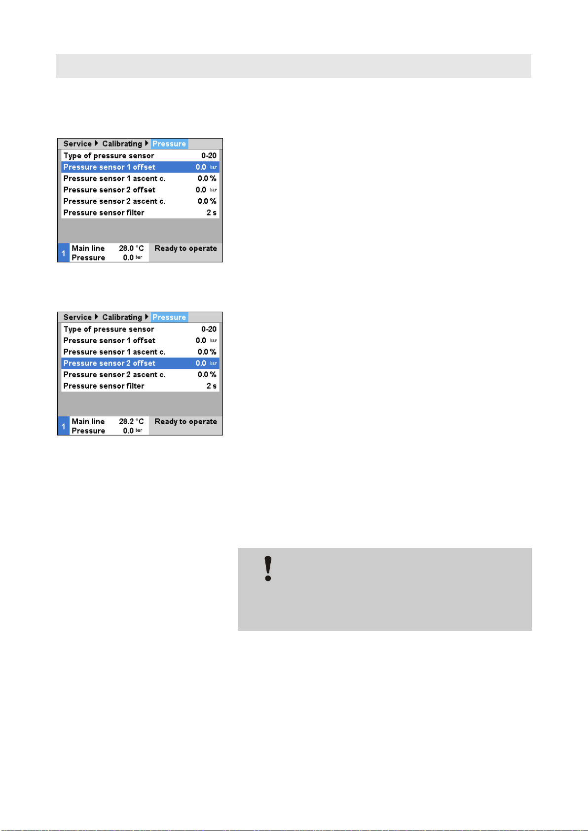
13.Calibrate the pressure sensor
with pressure sensor system (BP 1)
Fig. 10: Calibrate the pressure sensor 1
Read off the current System pressure actual value under
Display \ Actual value.
Set the parameter Pressure sensor 1 offset under Service \
Calibrating \ Pressure according to the following calculation:
Pressure sensor 1 offset new = Pressure sensor 1 offset
current –System pressure actual value current
with pressure sensor main line (BP 2)
Fig. 11: Calibrate the pressure sensor 2
Read off the current Main line pressure under Display \
Actual value
Set the parameter Pressure sensor 2 offset under Service \
Calibrating \ Pressure according to the following calculation:
Pressure Sensor 2 offset new = Pressure Sensor 2 offset
current –Main line pressure current
14.Check calibration pressure sensor
Parameter System pressure actual value resp. Main line
pressure under Display \ Actual value must be 0 bar ± 0,1.
If this is not the case, item calibration pressure sensor must be
repeated.
ATTENTION!
Risk of incorrect calibration!
False calibrations can lead to faults witch the unit.
Therefore:
–Check the calibrations.

Assembly Instructions M8095-EN
M8095-EN 2020-09 8/13
Fig. 12: Calibrating the flow rate
15.Flow rate calibration
(Software versions prior to SW51-1 0849B)
Operate unit in regular mode at 40 °C for at least 10 minutes.
Set Flow rate internal offset parameter in Service \ Calibrating \
Flow rate internally to "5 L/min".
Close shut-off valve between main or return line and wait for
1 minute.
Note current Flow rate.
Set Flow rate internal offset according to the following
calculation:
New Flow rate internal offset = 5 –current Flow rate
Open shut-off valve.
Fig. 13: Calibrating the flow rate
(From software version SW51-1 0849B onwards)
Operate unit in regular mode at 40 °C for at least 10 minutes.
Only for water units:
If available, set Pressure relief with unit OFF parameter in
Setting \ Miscellaneous to "OFF".
Switch off unit using button and wait at least 10 seconds.
Set Flow rate calibration parameter in Service \ Calibrating \
Flow rate internally to "ON".
The flow rate is calibrated automatically.
Only for water units:
If available, set Pressure relief with unit OFF parameter in
Setting \ Miscellaneous to "ON".
Switch on the unit using the key.

Assembly Instructions M8095-EN
M8095-EN 2020-09 9/13
16.Check flow rate calibration:
After calibration, run the unit for at least 5 minutes at 40 °C in
normal mode.
Close shut-off valve between feed and return lines.
Flow rate switches to 0 L/min and alarm indication ‚Flow rate
zero’is given.
NOTE!
The alarm message ‚Flow rate zero’ is delayed in
time.
If this is not the case, repeat the flow rate calibration.
ATTENTION!
Risk of incorrect calibration!
False calibrations can lead to faults witch the unit.
Therefore:
–Check the calibrations.
17.Acknowledge alarm and open shut-off valve.
18.Check unit functions.
19.Switch the unit off by press the key.

Assembly Instructions M8095-EN
M8095-EN 2020-09 10/13
Product group Treat-5 and Clean-5
1. Main switch off, remove the plug from the mains and empty
the unit.
2. Loosen the screws in the front panel and hinge it down.
3. Proceed as follows in order to remove the GIF-51 (A 4):
Remove all connectors.
Remove screws on the sides of the board.
Unplug the printed circuit board level measuring (A 10)
Fig. 14: Front panel
4. Change unit board GIF-51 (A 4):
Remove the printed circuit board level measuring (A 10) and
plug in on the new GIF-51.
Install new GIF-51 and fasten it with screw.
Connect plug connections.
Connection main pump cable (X 62/X 64):
Voltage 200–220 V Slot X 62 (triangle)
Voltage 380–480 V Slot X 64 (star)
Fig. 15: Voltage selection GIF-51
5. Voltage selection at X 15 with bridge plug (O/ID T21608):
Verify mains voltage (specification on the nameplate)
Place bridge according (Fig. 15)
ATTENTION!
Danger if wrongly connected
Wrong voltage selection or wrong connections can
damage the unit
Therefore:
–Thoroughly check connections and voltage
selection
6. Close and secure the front panel.
X 15
Assembly Instructions M8095-EN
M8095-EN 2020-09 11/13
7. Reconnect mains plug and switch on main switch.
NOTE!
The unit will maybe perform an automatic software
update.
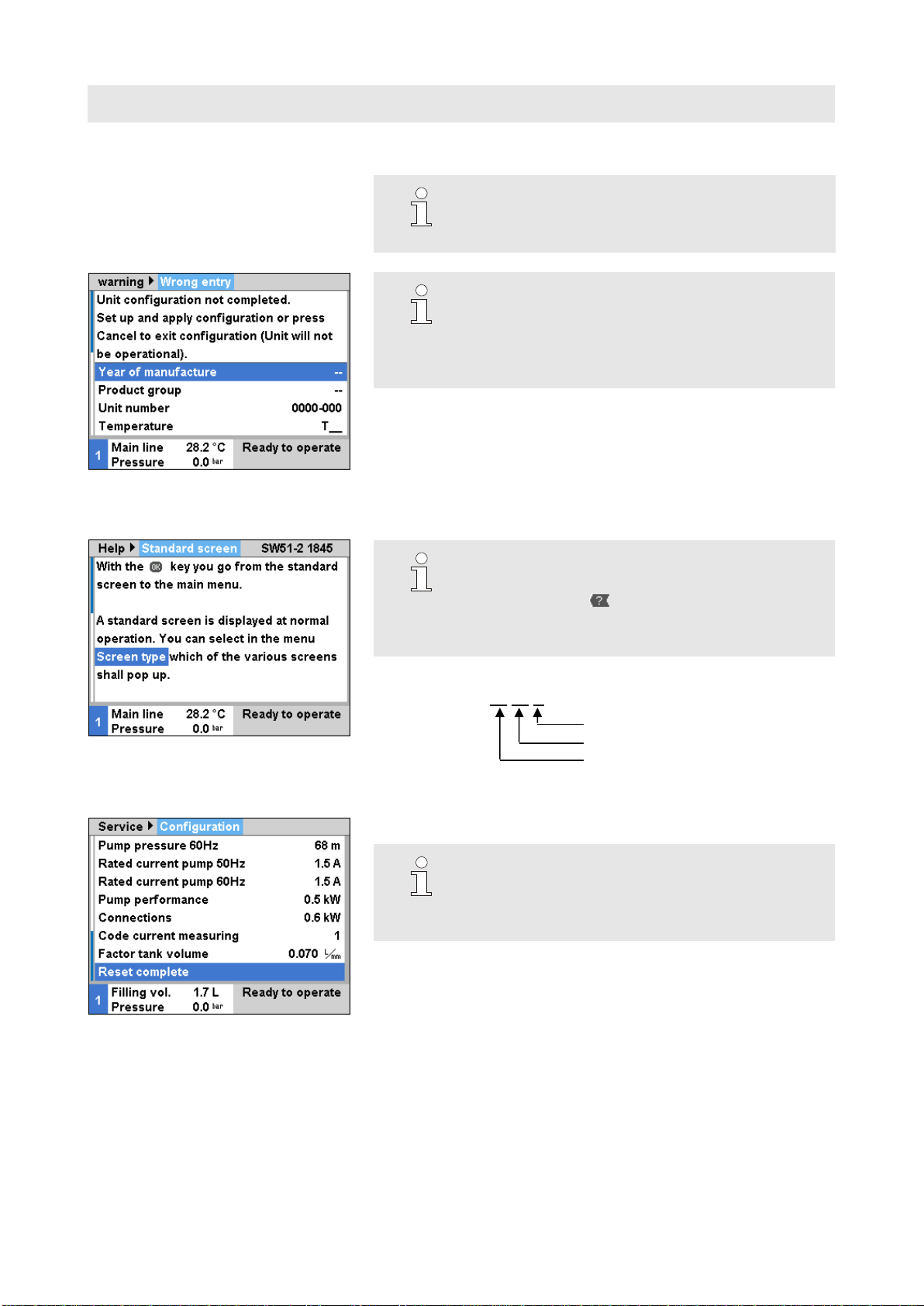
Fig. 16: Input window configuration
NOTICE!
If configuration is incomplete, the warning text
"Wrong entry" will be displayed. By cancelling the
configuration, the user can exit configuration mode
and subsequently conduct a Reset complete.
Fig. 17: Software version display
8. Checking the software version
NOTICE!
You can verify the currently installed software
version using the button on the basic screen.
The software version is indicated in the top right
corner (
Fig. 17).
Software version designation:
Ex. SW51-2 18 45 A
Index (optional)
Calendar week
Year
Fig. 18: Complete reset
9. Carrying out a complete reset
Service \ Configuration using "Support" user profile
NOTICE!
From software version SW51-1 0916 onwards, the
Service \ Configuration menu is accessed using the
code 1?2?.

Assembly Instructions M8095-EN
M8095-EN 2020-09 12/13
Fig. 19: Configuration
10.Configure unit
(to Software Version SW51-2 1431)
Service \ Configuration menu using the “Support” user profile.
NOTICE!
When configuring note the following:
- Select product group according to table below
- Check data on the nameplate
- Read appendix of Operating Manual
(for special versions)
Product group
Product type
TG
Thermo-5 temperature control unit
TR
Treat-5 water treatment unit
CL
Clean-5 cleaning unit
Fig. 20: Input window configuration
(from Software Version SW51-2 1449)
NOTICE!
As of software SW51-2 1449, the configuration is
requested after power ON automatically via the
input window (
Fig. 20).
11.Calibrate the pressure sensor
Fig. 21: Calibrate the pressure sensor 2
Read off the current Main line pressure under Display \
Actual value
Set the parameter Pressure sensor 2 offset under Service \
Calibrating \ Pressure according to the following calculation:
Pressure Sensor 2 offset new = Pressure Sensor 2 offset
current –Main line pressure current

Assembly Instructions M8095-EN
M8095-EN 2020-09 13/13
12.Check calibration pressure sensor
Parameter System pressure actual value resp. Main line
pressure under Display \ Actual value must be 0 bar ± 0,1.
If this is not the case, item calibration pressure sensor must be
repeated.
ATTENTION!
Risk of incorrect calibration!
False calibrations can lead to faults witch the unit.
Therefore:
–Check the calibrations.
13.Check unit functions.
14.Switch the unit off by press the key.
Parts list
Pos
Description
O/ID
O/ID
T27401
T27401-1
T27401-2
T25240
T25240-1
Pcs
Pcs
Pcs
Pcs
Pcs
01
Unit board GIF-51
T27400
1
-
-
1
-
02
Unit board GIF-51 finished
T27400-1
-
1
-
-
1
03
Unit board GIF-51 UL
T27400-2
-
-
1
-
-
04
Plug jumper voltage pre-selection
(mounted on X 15, 400 V as standard setting)
T21608
1
1
1
1
1
05
Assembly instructions German
M8095-DE
1
1
1
1
1
06
Assembly instructions English
M8095-EN
1
1
1
1
1
07
Assembly instructions French
M8095-FR
1
1
1
1
1
Table of contents


