HBM VKK1-4 User manual

VKK1R4
VKK14
A23261.0en/de/fr
Junction boxes
Klemmenkästen
Boîtiers de raccordement
VKK14
VKK1R4
Mounting instructions
Montageanleitung
Notice de montage

English Page 3 − 16. . . . . . . . . . . . . . . . . . . . . . . . . . . . . . . . . . . . . . . . . . . . . . . . .
Deutsch Seite 17 − 30. . . . . . . . . . . . . . . . . . . . . . . . . . . . . . . . . . . . . . . . . . . . . . .
Français Page 31 − 44. . . . . . . . . . . . . . . . . . . . . . . . . . . . . . . . . . . . . . . . . . . . . . .

3
VKK14 / VKK1R4
A23261.0 en/de/fr HBM
Content Page
Safety instructions 4. . . . . . . . . . . . . . . . . . . . . . . . . . . . . . . . . . . . . . . . . . . . .
1 Special features 7
. . . . . . . . . . . . . . . . . . . . . . . . . . . . . . . . . . . . . . . . . . . . .
2 Installing the terminal boxes 8. . . . . . . . . . . . . . . . . . . . . . . . . . . . . . . . .
2.1 Mounting dimensionsVKK14 / VKK1R4 8. . . . . . . . . . . . . . . . . .
2.2 Tightening the mounting screwsof the cover plate 9. . . . . . . . . .
3Preparing the cables 10. . . . . . . . . . . . . . . . . . . . . . . . . . . . . . . . . . . . . . . .
4 Connection 11. . . . . . . . . . . . . . . . . . . . . . . . . . . . . . . . . . . . . . . . . . . . . . . . .
5Cornerload balancing 12. . . . . . . . . . . . . . . . . . . . . . . . . . . . . . . . . . . . . . .
6 Technicalrecommendations 13. . . . . . . . . . . . . . . . . . . . . . . . . . . . . . . . .
7 Special instructions 15. . . . . . . . . . . . . . . . . . . . . . . . . . . . . . . . . . . . . . . . .
8 Specifications 16. . . . . . . . . . . . . . . . . . . . . . . . . . . . . . . . . . . . . . . . . . . . . .
8.1 SpecificationsVKK14 / VKK1R4 16. . . . . . . . . . . . . . . . . . . . . . . .

4VKK14 / VKK1R4
A23261.0 en/de/frHBM
Safety instructions
Use in accordance with the regulations
In the interests of safety, the terminal box should only be operated as
described in the Installation Instructions. It is also essential to observe the
appropriate legal and safety regulations for the application concerned during
use. The same applies to the use of accessories.
The terminal box is not a safety element within the meaning of its use as
intended. For safe and troublefree operation, this terminal box must not only
be correctly transported, stored, sited and installed but must also be carefully
operated and maintained.
General dangers of failing to follow the safety instructions
The terminal box corresponds to the state of the art and is failsafe. Terminal
boxes can give rise to remaining dangers if they are inappropriately installed
and operated by untrained personnel.
Everyone involved with the installation, commissioning, maintenance or repair
of a terminal box must have read and understood the Installation Instructions
and in particular the technical safety instructions.
Symbol: NOTE
Means that important information about the product or its handling is being
given.

5
VKK14 / VKK1R4
A23261.0 en/de/fr HBM
Remaining dangers
The scope of supply and performance of the terminal box covers only a small
area of connection technique. In addition, equipment planners, installers and
operators should plan, implement and respond to the safety engineering
considerations of the connection technique in such a way as to minimize
remaining dangers. Prevailing regulations must be complied with at all times.
There must be reference to the remaining dangers associated with the
connection technique. In these Installation Instructions remaining dangers are
pointed out using the following symbols:
Symbol: CAUTION
Meaning: Potentially dangerous situation
Warns of a potentially dangerous situation in which failure to comply with
safety requirements could lead to damage to property and slight or moderate
physical injury.
Qualified personnel
The terminal box must only be installed by qualified personnel, strictly in
accordance with the specifications and with the safety requirements and
regulations listed below. It is also essential to observe the appropriate legal
and safety regulations for the application concerned. The same applies to the
use of accessories.
Qualified personnel means persons entrusted with the installation, assembly,
commissioning and operation of the product who possess the appropriate
qualifications for their function.
Conditions on site
Do not allowthe terminal box to become dirty or damp.
Maintenance
The terminal box gives degree of protection IP65 (dusttight, protected against
water jets). Make regular checks to ensure the tightness and efficiency of the
rubber lid seal and the screwfittings.
Prevention of accidents
The prevailing accident prevention regulations must be observed.

6VKK14 / VKK1R4
A23261.0 en/de/frHBM
Unauthorized conversions and modifications are prohibited
Neither the design of the device nor any technical safety aspects may be
modified without the express permission of Hottinger Baldwin Messtechnik
GmbH. Any modification excludes Hottinger Baldwin Messtechnik GmbHfrom
any and all liability for any damage resulting therefrom.
It is strictly forbidden to carry out any repairs and soldering work on the
motherboards or to replace any components. Repairs may only be carried out
by persons authorized thereto by Hottinger Baldwin Messtechnik GmbH.
•During installation and when connecting the cables, take action to prevent
electrostatic discharge as this may damage the connected electronics.
•When connecting additional devices, comply with the safety requirements
for electrical measurement, control, regulatory and laboratory equipment
(EN61010).
•All the interconnecting cables must be shielded cables. The screen must
be connected extensively to ground on both sides.

7
VKK14 / VKK1R4
A23261.0 en/de/fr HBM
1 Special features
− Parallel connection of max. four load cells (VKK14, VKK1R4)
−HBM’s shielding design provides EMCproofing under EN45 501
− Corner load balancing via the integrated resistor network in the load cell
output
− Degree of protection IP65 to EN60 529
The terminal boxes also allowthe screen to be connected conventionally by
means of the screen strands. With this method, EMCproofing under
EN45 501 is restricted, which can lead to measurement errors when there
are electromagnetic interference fields.

8VKK14 / VKK1R4
A23261.0 en/de/frHBM
2 Installing the terminal boxes
The best way to fit the VKK... terminal boxes is with the grommets pointing
downward. This makes it more difficult for moisture to get in.
2.1 Mounting dimensions VKK14 / VKK1R4
Suitable fastening screws: M4 DIN84 or B3.9 DIN7971 (minimum screwlength 20 mm)
∅4...6.5
52
163
84
179
50...100*
6
18 45
SW14
30
* depending on the cable type
Grounding screw
M5x10 DIN84
Mounting direction
Fig.2.1: Mounting dimensions of the VKK14
176
186
36
100
110
125204
5x M12, SW14,
for cable ∅4 ... 6,5 mm
Mounting direction
190
M4
7
Fig.2.2: Mounting dimensions of the VKK1R4

9
VKK14 / VKK1R4
A23261.0 en/de/fr HBM
2.2 Tightening the mounting screws of the coverplate
Terminal box viewed from above
Tighten the mounting screws of the cover plate in the following sequence:
1. 4.
2.
3.
Maximum tightening torque
of the mounting screws:
2.5N⋅m
Fig.2.3: Tightening the mounting screws of the coverplate
10 VKK14 / VKK1R4
A23261.0 en/de/frHBM
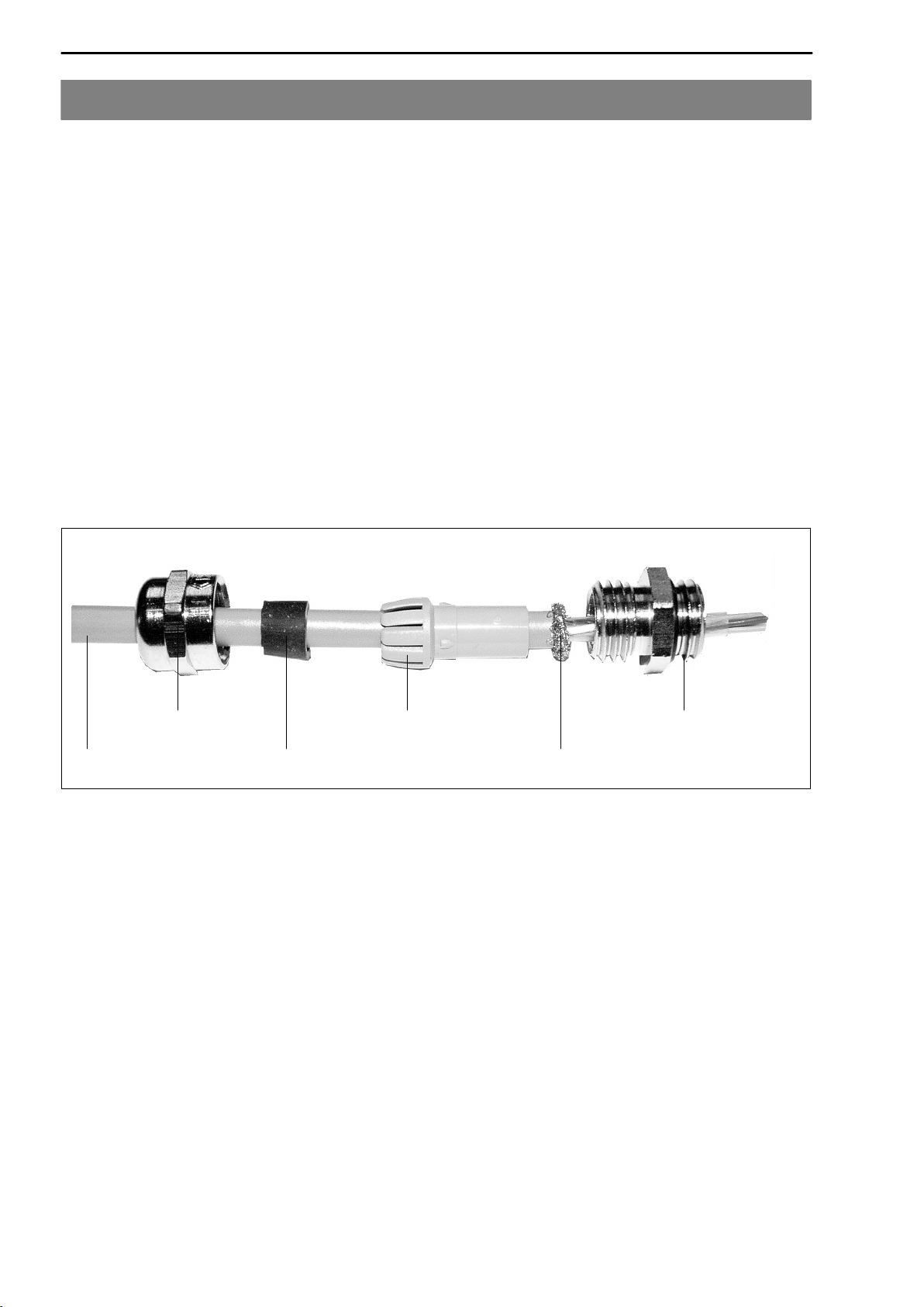
3Preparing the cables
For optimum results, proceed as follows:
DRemove the outer sheath of the cable and depending on the cable
diameter, expose the braided screen for about 8 ... 15 mm.
DPush the cap nut and the bladed insert with the sealing ring onto the cable.
DBend the braided screen outward at right angles (90°).
DCrimp the braided screen over towards the outer sheath of the cable, i.e.
fold it a further 180°.
DSlip the intermediate connection piece on as far as the braided screen,
quickly turning it to and fro around the cable axis.
DPush the bladed insert with the sealing ring into the intermediate connection
piece and engage the locking element.
DFirmly tighten the cap nut
shielded cable
cap nut
sealing ring
bladed insert
braided screen
intermediate connectio
n
Fig.3.1: Preparing a connection cable

11
VKK14 / VKK1R4
A23261.0 en/de/fr HBM
4Connection
The terminals are identified as shown in the following diagram. The colors
correspond to the wire colors used by HBM load cells.
(white)
(black)
(gray)
Excitation (+)
(green)
(red)
Excitation (−)
Sense (−)
Signal (+)
(blue) Sense (+)
Signal (−)
Screen (Shield)
(connected to housing)
Wiring code (6wire circuit):
To achieve the bestpossible measurement results and to optimize
interference immunity, connect to the weighing electronics with HBM cables
using 6wire circuitry.
If the load cells and the weighing electronics use 4wire circuitry, the sense
terminals are unused.
If the load cells use 4wire circuit and the weighing electronic use 6wire
circuit, the terminal for sense (+) must be bridged with the terminal for
excitation (+) as well as the terminal for sense (−) with the terminal for
excitation (−). See also the Installation Instructions for the corresponding load
cell.
CAUTION
All unused grommets must be closed off with the plugs provided forthe
purpose. Tighten the associated sleeve nut in each case to stop the
moisture getting in.
12 VKK14 / VKK1R4
A23261.0 en/de/frHBM
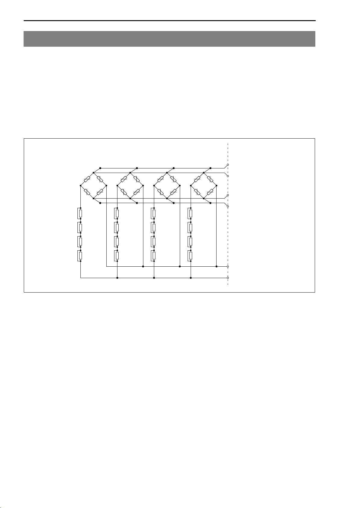
5Cornerload balancing
With weighing machines, mechanical imbalance may lead to corner load
errors. According to the EN45501 3.6.2 standard for nonautomatic weighing
machines, specific values are to be maintained for eccentric loading. The
terminal boxes provide an easy way to compensate for these errors
electrically. A binarystepped network of 4 resistors is available for each load
cell, that is shorted at the factory via 0 Ωresistors (see Fig.5.1). Opening the
vertical 0 Ωresistors activates the relevant resistances and thus reduces the
load cell signal.
Sense (+)
Sense (−)
Excitation (+)
Excitation (−)
Signal (−)
Signal (+)
0.39Ω
0.82Ω
1.50Ω
3.00Ω
0.39Ω
0.82Ω
1.50Ω
3.00Ω
0.39Ω
0.82Ω
1.50Ω
3.00Ω
0.39Ω
0.82Ω
1.50Ω
3.00Ω
4321
Output: AmplifierInput: Load cells 1 ... 4
Fig.5.1: Resistornetwork forcornerload balancing of 4 load cells

13
VKK14 / VKK1R4
A23261.0 en/de/fr HBM
6 Technical recommendations
Practical example using a platform with 4 load cells:
DWhen the four corners of the platform are loaded, note the weighing
machine signals in order to assess the respective differences (in kg) to the
corner of the weighing machine (load cell) with the lowest indication. This
load cell is the reference load cell (4) and does not need balancing (in the
example in Fig.6.1, load cell 4).
DThe chart (Fig.6.2) is graduated in three test load ranges. Select the test
loads used (50kg...30t) in the relevant line. Starting from the calculated
corner load error difference on the Xaxis, look for the intersection with the
test load and then, on the Yaxis, read off the resistance and the most
suitable combination. The resistance values here apply for 350 Ωload cells
(see the table in the lid of the VKK...).
In our example, load cell 3 has a corner load error of 80kg, which produces
an adjustment resistance of 1.5+0.82Ω(shown in Fig.6.2).
Load cell 1
12,600 kg
Load cell 2
12,550 kg
Load cell 3
12,530 kg
Reference load cell 4
12,450 kg
Test load
12.5 t
(Example: Reference load cell +80kg)
Fig.6.1: Typical Platform weighing machine with fourload cells with 12.5t
test load
DFor the load cell affected (e.g. load cell 3), the necessary resistances are
activated by opening the relevant "0 Ωresistor". Tip: Divide the wire and
bend it to one side
DRepeat this procedure for all the load cells apart from the ’reference load
cell’ (in our example, this is load cell 4).

14 VKK14 / VKK1R4
A23261.0 en/de/frHBM
Cornerload errorin kg
Test load
AdjustmentresistanceRinohms
50kg
0.5t
5t
100kg
1t
10t
125kg
1.25t
12.5t
150kg
1.5t
15t
200kg
2t
20t
250kg
2.5t
25t
300kg
3t
30t
0.39+0.82+1.5+3Ω
0.39+1.5+3Ω
1.5+3Ω
0.39+0.82+3Ω
0.82+3Ω
0.39+3Ω
3Ω
0.39+0.82+1.5Ω
0.82+1.5Ω
0.39+1.5Ω
1.5Ω
0.39+0.82Ω
0.82Ω
0.39Ω
−
0.2
2
20
1
10
100
2
20
200
3
30
300
4
40
400
5
50
500
Example:
test load: 12.5t
corner load error: 80kg
80
Resistance
of your choice
Fig.6.2: Cornerload balancing for350 Wload cells
(For 700 Ωload cells, the established value must be doubled.)

15
VKK14 / VKK1R4
A23261.0 en/de/fr HBM
7 Special instructions
For other test loads types (e.g. building site vehicle testing), the user can
extend the chart by drawing an additional line between the zero point and the
actual test load used.
If the corner load errors are particularly high or if the load cells have an input
resistance of more than 350 Ω, it may be that the total value of the resistor
network is insufficient. In these cases, remove the "0 Ωresistor" (R19,
R29,...,R69) and replace with a resistor of your choice. This resistance will be
added to that of the network.
If the chart is not big enough, the adjustment resistance can be calculated as
follows:
R(EA) = adjustment resistance (Ω)
R(AW) = output resistance of the load cell (Ω)
L(E) = measured corner load error (kg)
L(P) = test load (kg)
R(EA)+
R(AW)·L(E)
L(P)
In this case, you should first check the installation for possible errors.
Note
The bases forcalculation described in this section forcornerload
balancing and appearing in the form of a chart, a table ora formula,
apply to load cells with a symmetrical output voltage. In practice, the
balancing effect may differfrom the target value, depending of the type
of load cell involved. In this case, you will have to use empirical values
forbalancing.

16 VKK14 / VKK1R4
A23261.0 en/de/frHBM
8 Specifications
8.1 Specifications VKK14 / VKK1R4
Type VKK14 VKK1R4
Resistornetwork
forcornerload balancing Ω0.39...5.71 (in 15 steps)
Max. permissible voltage V 18
Nominal temperature range
°C
−20...+85
Operating temperature range −20...+85
Storage temperature range −40...+85
Interference immunity check
Electromagnetic field
(26...1000MHz) V/m 10
Burst (to connected cables) V 1000
Electrostatic discharge
(to housing) V 6000
Weight, approx. kg 1 1.5
Max. wire cross section
of cable strands mm21.5
Degree of protection
according to EN60529
(IEC 529) IP65 (dusttight and protected against water jets)
Materials Housing
Sleeve nut
Clamping cone
Diecast aluminum, coated
(color: RAL 7001)
PG7, SW14,
nickelplated brass
Neoprene,
for cable −∅4...6.5mm
Stainless steel
M12, SW14,
nickel−plated brass
Neoprene,
for cable −∅4...6.5mm

17
VKK14 / VKK1R4
A23261.0 en/de/fr HBM
Inhalt Seite
Sicherheitshinweise 18. . . . . . . . . . . . . . . . . . . . . . . . . . . . . . . . . . . . . . . . . . . .
1 CharakteristischeMerkmale 21. . . . . . . . . . . . . . . . . . . . . . . . . . . . . . . . .
2 Montage derKlemmenkästen 22. . . . . . . . . . . . . . . . . . . . . . . . . . . . . . . .
2.1 MontageabmessungenVKK14 / VKK1R4 22. . . . . . . . . . . . . . . .
2.2 Anziehen der Montageschrauben desDeckels23. . . . . . . . . . . . .
3KonfektionierungderKabel 24. . . . . . . . . . . . . . . . . . . . . . . . . . . . . . . . . .
4Anschließen 25. . . . . . . . . . . . . . . . . . . . . . . . . . . . . . . . . . . . . . . . . . . . . . . .
5 Eckenlastabgleich 26. . . . . . . . . . . . . . . . . . . . . . . . . . . . . . . . . . . . . . . . . .
6 TechnischeEmpfehlungen 27. . . . . . . . . . . . . . . . . . . . . . . . . . . . . . . . . . .
7 Spezielle Hinweise 29. . . . . . . . . . . . . . . . . . . . . . . . . . . . . . . . . . . . . . . . . .
8 Technische Daten 30. . . . . . . . . . . . . . . . . . . . . . . . . . . . . . . . . . . . . . . . . . .
8.1 Technische Daten VKK14 / VKK1R4 30. . . . . . . . . . . . . . . . . . . . .

18 VKK14 / VKK1R4
A23261.0 en/de/frHBM
Sicherheitshinweise
BestimmungsgemäßerGebrauch
Zur Gewährleistung eines sicheren Betriebes darf der Klemmenkasten nur
nach den Angaben in der Montageanleitung verwendet werden. Bei der Ver
wendung sind zusätzlich die für den jeweiligen Anwendungsfall erforderlichen
Rechtsund Sicherheitsvorschriften zu beachten. Sinngemäß gilt dies auch
bei Verwendung von Zubehör.
Der Klemmenkasten ist kein Sicherheitselement im Sinne des bestimmungs
gemäßen Gebrauchs. Der einwandfreie und sichere Betrieb dieses Klemmen
kastens setzt sachgemäßen Transport, fachgerechte Lagerung, Aufstellung
und Montage sowie sorgfältige Bedienung und Instandhaltung voraus.
Allgemeine Gefahren bei Nichtbeachten derSicherheitshinweise
Der Klemmenkasten entspricht dem Stand der Technik und ist betriebssicher.
Von den Klemmenkasten können Restgefahren ausgehen, wenn sie von un
geschultem Personal unsachgemäß eingesetzt und bedient werden.
Jede Person, die mit Aufstellung, Inbetriebnahme, Wartung oder Reparatur
eines Klemmenkastens beauftragt ist, muss die Montageanleitung und insbe
sondere die sicherheitstechnischen Hinweise gelesen und verstanden haben.
Symbol: HINWEIS
Weist darauf hin, dass wichtige Informationen über das Produkt oder über die
Handhabung des Produktes gegeben werden.

19
VKK14 / VKK1R4
A23261.0 en/de/fr HBM
Restgefahren
Der Leistungs und Lieferumfang des Klemmenkastens deckt nur einen Teil
bereich der Anschlusstechnik ab. Sicherheitstechnische Belange der An
schlusstechnik sind zusätzlich vom Anlagenplaner/Ausrüster/Betreiber so zu
planen, zu realisieren und zu verantworten, dass Restgefahren minimiert wer
den. Jeweils existierende Vorschriften sind zu beachten. Auf Restgefahren im
Zusammenhang mit der Anschlusstechnik ist hinzuweisen. In dieser Monta
geanleitung wird auf Restgefahren mit folgenden Symbol hingewiesen:
Symbol: ACHTUNG
Bedeutung: Möglicherweise gefährliche Situation
Weist auf eine mögliche gefährliche Situation hin, die − wenn die Sicherheits
bestimmungen nicht beachtet werden − Sachschaden, leichte oder mittlere
Körperverletzung zur Folge haben könnte.
Qualifiziertes Personal
Der Klemmenkasten ist nur von qualifiziertem Personal ausschließlich ent
sprechend der technischen Daten in Zusammenhang mit den nachstehend
ausgeführten Sicherheitsbestimmungen und Vorschriften einzusetzen. Hierbei
sind zusätzlich die für den jeweiligen Anwendungsfall erforderlichen Rechts
und Sicherheitsvorschriften zu beachten. Sinngemäß gilt dies auch bei Ver
wendung von Zubehör.
Qualifiziertes Personal sind Personen, die mit Aufstellung, Montage, Inbe
triebsetzung und Betrieb des Produktes vertraut sind und die über die ihrer
Tätigkeit entsprechende Qualifikationen verfügen.
Bedingungen am Aufstellungsort
Schützen Sie den Klemmenkasten vor der Einwirkung von Schmutz und
Feuchtigkeit.
Wartung
Der Klemmenkasten ist in Schutzart IP65 ausgeführt (Staubschutz, Schutz
gegen Strahlwasser). Kontrollieren Sie in gewissen Zeitabständen die Dicht
funktion der Gummidichtung des Deckels und der Verschraubungen.
Unfallverhütung
Die einschlägigen Unfallverhütungsvorschriften der Berufsgenossenschaften
müssen berücksichtigt werden.

20 VKK14 / VKK1R4
A23261.0 en/de/frHBM
Verbot von eigenmächtigen Umbauten und Veränderungen
Das Gerät darf ohne ausdrückliche Zustimmung von der Hottinger Baldwin
Messtechnik GmbHweder konstruktivnoch sicherheitstechnisch verändert
werden. Jede Veränderung schließt eine Haftung seitens der Hottinger Bald
win Messtechnik GmbHfür daraus resultierende Schäden aus.
Jegliche Reparaturen, Lötarbeiten an den Platinen sowie ein Austauschen
von Bauteilen ist strengstens untersagt. Reparaturen dürfen ausschließlich
durch von der Hottinger Baldwin Messtechnik GmbHautorisierte Personen
ausgeführt werden.
•Treffen Sie bei der Montage und beim Anschluss der Leitungen
Maßnahmen gegen elektrostatische Entladungen, um eine Beschädigung
der angeschlossenen Elektronik zu vermeiden.
•Beim Anschluss von Zusatzeinrichtungen sind die
Sicherheitsbestimmungen für elektrische Mess, Steuer, Regel und
Laborgeräte (EN61010) einzuhalten.
•Für alle Verbindungsleitungen sind geschirmte Leitungen zu verwenden.
Der Schirm ist beidseitig flächig mit Masse zu verbinden.
This manual suits for next models
1
Table of contents
Languages:


