HCW MAHRW020W/P(03) Service manual

AIR TO WATER HEAT PUMP
WATER HEATER
AIR TO WATER HEAT PUMP
WATER HEATER
Installation & instruction manualInstallation & instruction manual
MK3068/MK3069MK3068/MK3069
HCWHCW////


I Specification................................................................
1. ...............................................................
2. Parameter of multi-function air to water heat pump...................
3. Product appearance and installation dimension......................
II Installation..................................................................
1. Unit installation position........................................................
2.
. Water Pipe connection.........................................................
5. Electric wiring....................................................................
6.Selection of Electrical Wire...................................................
7.Trial operation(should be operated by professionals)..............
III Use...........................................................................
1. Function diagram of the remote controller..............................
2. Use of remote controller......................................................
3.Operation data setting.........................................................
IV Maintenance and repair............................................
1. Malfunction Indicating Table................................................
V Installation sketch.....................................................
1. The choice of installation ways.............................................
VI
1. Indoor unit wiring diagram...................................................
2.Outdoor unit wiring diagram .................................................
Model Nomenclature
The refrigerant piping connection for split type unit..................
3. Refrigerant recovery method................................................
4
Appendix .................................................................
CONTENTS
Air To Water Heat Pump Water Heater
1
1
2
3
4
4
5
7
7
7
7
8
9
10
10
10
14
16
16
17
17
23
23
23

Notice
1.1 In order to use this product better and safer, please read this instruction carefully before install
and operate it. Please pay attention to all the notice in operation and maintenance. Save all
manuals and documentation for future reference.
1.2 All in one heat pump is a special appliance. Improper installation will cause damage and danger.
It should be installed and maintained by the professionals. Please contact our authorized local
service point for installation and maintenance. Please read and follow this instruction carefully
before and during installation.
Remarks:
We will not bear the responsibility for any personal injury or unit damage caused by
non-Compliance of the regulations and instruction in this manual.
1.3 Please check whether the distribution power capacity, switch and socket are compliance with
the requirements of our unit power. Details please refer to the rating label or parameter table
in this manual.
1.4 The power should be equipped with leakage protection separately. Power cable should be
chosen in accordance with the operation requirements of the unit.
1.5 The unit must be grounded safely. Do not use the unit if grounded unsafely. Do not connect
the ground line to the neutral and or tap water pipe.
1.6 The wire must be joined in compliance with the requirements of the wiring chart. Do not
alternate and or repair the unit personally.
1.7 Do not install the unit closed to inflammable, explosive and naked light spot.
1.8 To ensure the unit operate properly, please equipped with a filter in the water input when
installation.
1
1 Model Nomenclature
MA HR W - - W A B / P S ( )
Source medium
MA: Airsource
MW: Ground source
Function of the unit
HR:heating
Energy exchange medium
A: Refrigerant
W: Water
Z: Integrated type
W: Split type(indoor unit )
A: coil heating
B: circulating heating
(Omit the split type unit model)
A: Horizontal fan direction
B: Upward fan direction
C:Double air duct type
(Omit the split type unit model)
01:hot water+solar
02:hotwater (EVI)
03:hot water+heating/cooling+solar
The figure represents the horse power of unit
eg:010 means 1 horse power
P:with built inpump
(without built in pump omitted)
S:3phase (single phase omitted)
I SpecificationI Specification
Air To Water Heat Pump Water Heater
The figure represents the horse power of unit
eg:010 means 1 horse power
A: Horizontal fan direction
B: Upward fan direction
Design alternative serial number
MA FP - - A ( )
Energy exchange medium
MA: Refrigerant
MW: Water
FP: Fan coil
Outdoor unit model nomenclature
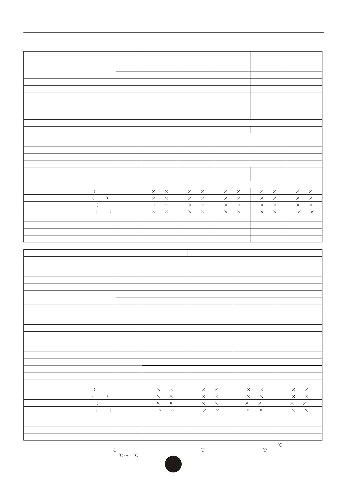
020W/P(03)
020A
5.0
17100
1.55
7.0
6.0
20500
1.75
8.0
50
Rotary
1
1
1/4
1/2
1
2-3
610 440 750
665 480 770
840 350 610
980 410 665
52
57
39
44
Indoor Unit Model
Outdoor Unit Model
Rated Input Power
Rated Input Current
Rated Input Power
Rated Input Current
Power Supply
Noise
Compressor
Compressor Qty
Fan Qty
Refrigerant Liquid Pipe
Refrigerant Gas Pipe
Water Outlet/Water Inlet
Water Flow Volume
Refrigerant Gas Type
Indoor Unit Net Dimensions(L/M/H
Indoor Unit Shipping Dimensions L/M/H
Outdoor Unit Net Dimensions(L/M/H
Outdoor Unit Shipping Dimensions L/M/H
Indoor Unit Net Weight
Indoor Unit Shipping Weight
Outdoor Unit Net Weight
Outdoor Unit Shipping Weight
MAHRW
MAFP
kW
BTU/h
kW
A
kW
BTU/h
kW
A
V/PH/Hz
dB(A)
inch
inch
inch
3
m/h
mm
mm
mm
mm
kg
kg
kg
kg
R410A
(208~230)ACV/1PH/60Hz
Rated Cooling Capacity
Rated Heating Capacity
025W/P(03)
025A
6.5
22200
2.10
9.5
7.5
25600
2.30
10.5
50
Rotaty
1
1
1/4
1/2
1
2-3
610 440 750
665 480 770
840 350 610
980 410 665
53
58
39
44
030W/P(03)
030A
7.5
25600
2.40
10.9
9.0
30800
2.70
12.3
50
Rotaty
1
1
3/8
1/2
1
2-3
610 440 750
665 480 770
830 380 710
965 410 750
55
60
45
50
035W/P(03)
035A
9.0
30800
2.90
13.2
10.5
35900
3.10
14.1
50
Rotaty
1
1
3/8
1/2
1
2-3
610 440 750
665 480 770
830 380 710
965 410 750
57
62
45
50
040W/P(03)
040A
10.0
34200
3.10
14.5
12.0
41000
3.60
16.4
50
Scroll
1
1
3/8
1/2
1
3-4
600 630 785
710 750 915
880 420 800
1020 450 830
100
108
58
65
Indoor Unit Model
Outdoor Unit Model
Rated Input Power
Rated Input Current
Rated Input Power
Rated Input Current
Power Supply
Noise
Compressor
Compressor Qty
Fan Qty
Refrigerant Liquid Pipe
Refrigerant Gas Pipe
Water Outlet/Water Inlet
Water Flow Volume
Refrigerant Gas Type
Indoor Unit Net Dimensions(L/M/H
Indoor Unit Shipping Dimensions L/M/H
Outdoor Unit Net Dimensions(L/M/H
Outdoor Unit Shipping Dimensions L/M/H
Indoor Unit Net Weight
Indoor Unit Shipping Weight
Outdoor Unit Net Weight
Outdoor Unit Shipping Weight
MAHRW
MAFP
kW
BTU/h
kW
A
kW
BTU/h
kW
A
V/PH/Hz
dB(A)
inch
inch
inch
3
m/h
mm
mm
mm
mm
kg
kg
kg
kg
R410A
(440~460)ACV/3PH/60Hz
Rated Cooling Capacity
Rated Heating Capacity
040W/PS(03)
040A
10.0
34200
3.20
5.6
12.0
41000
3.6
6.3
50
Scroll
1
1
3/8
5/8
1
3-4
600 630 785
710 750 915
880 420 800
1020 450 830
100
108
58
65
045W/PS(03)
045A
11.5
39300
3.60
6.3
13.5
46100
4.0
7.0
50
Scroll
1
1
3/8
5/8
1
3-4
600 630 785
710 750 915
880 420 800
1020 450 830
105
112
58
65
050W/PS(03)
050A
12.5
42700
4.0
7.0
15.0
51200
4.5
7.9
50
Scroll
1
2
3/8
5/8
1
3-4
600 630 785
710 750 915
880 470 1250
1010 525 1280
110
118
60
75
060W/PS(03)
060A
15.0
51200
4.70
8.2
18.0
61500
5.30
9.3
50
Scroll
1
2
3/8
5/8
1
3-4
600 630 785
710 750 915
880 470 1250
1010 525 1280
115
122
60
75
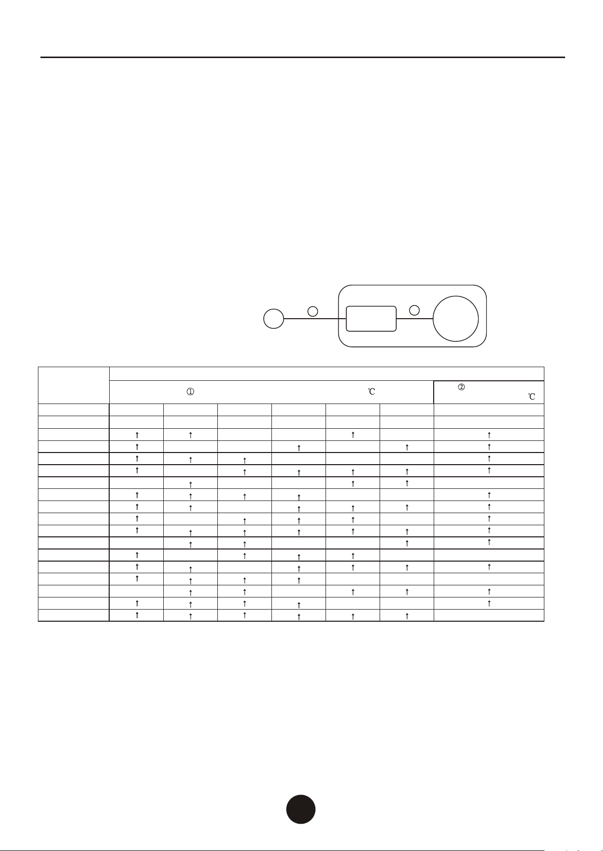
2.Parameter of multi-function air to water heat pump
Air To Water Heat Pump Water Heater
22
Note: (1)The manualis a technicalparameters measured inthe following conditions: outdoor dry temperature is 20
and wet bulbtemperature is 15 ,the temperature ofwater inflow is 15 and of wateroutflow is 55 .
(2)Using in ambienttemperature:-15 45

3. Product appearance and installation dimension
33
Air To Water Heat Pump Water Heater
DC
A
B
D
A
B
C
D
A
B
C
A
B
C
D
DA
B
C
A
B
C
D
3.1Installation dimension of integrated type unit
3.2Installation dimension of split type unit
A
B
C
D
Size
Units: mm
MODEL
360
405
550
750
MAHRW020W/P(03)
MAHRW025W/P(03)
MAHRW030W/P(03)
MAHRW035W/P(03)
A
B
C
D
Size
Units: mm
MODEL
495
320
840
610
MAFP020A
MAFP025A
A
B
C
D
Size
Units: mm
MODEL
515
340
830
710
MAFP030A
MAFP035A
A
B
C
D
Size
Units: mm
MODEL
615
390
880
800
MAFP040A
MAFP045A
A
B
C
D
Size
Units: mm
MODEL
525
440
885
1250
MAFP050A
MAFP060A
A
B
C
D
Size
Units: mm
MODEL
635
450
780
765
MAHRW040W/P(03)
MAHRW040W/PS(03)
MAHRW050W/PS(03)
MAHRW060W/PS(03)
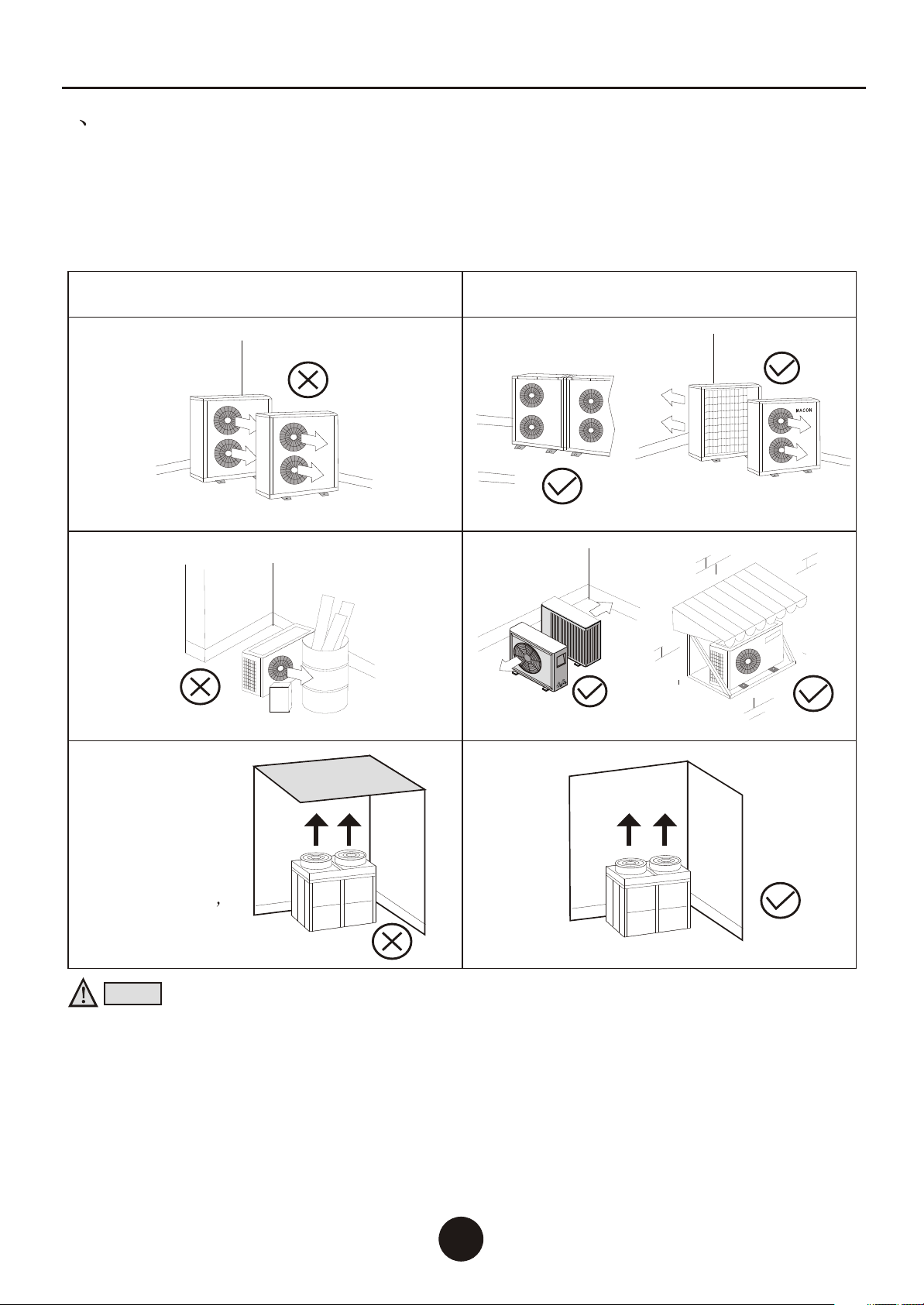
1. unit installation position
The pretty high condensation temperature (cooling) and pretty low evaporation temperature
(heating) will affect the operation of outdoor unit. To achieve maximum efficiency, please select
the installation position under below regulations:
To avoid ventilation short, the outdoor unit discharged air should not return when installation.
Please keep enough space around the outdoor unit for repair. Right and wrong means as below:
Wrong Right
As the upwards fan
direction unit
exhausts air
upwards, do not
place any object up
the unit.
Please built an
introductory
equipment if can t
avoid this object.
Notice:
1. To get enough air for ventilation of the unit, the installation position should be with good
ventilation.
2.The installation position can hold the outdoor unit without noise and shake.
3.No sunlight to the unit. Set an awning if necessary.
4.The water from rain and defrosting can be discharged in the installation position.
5.The unit will not be covered by snow in the installation position.
6.The discharged air will not face strong air in the installation position.
7.Assure the noise caused by the unit ventilation and operation will not affect the neighbor.
8.The installation position will not be affected by garbage, oil and mist.
9.The outdoor unit will be damaged under the condition with oil(engine oil), salt(sea area) and
sulfide air(near thermal spring and refining factory).
44
II Installation
Air To Water Heat Pump Water Heater
55
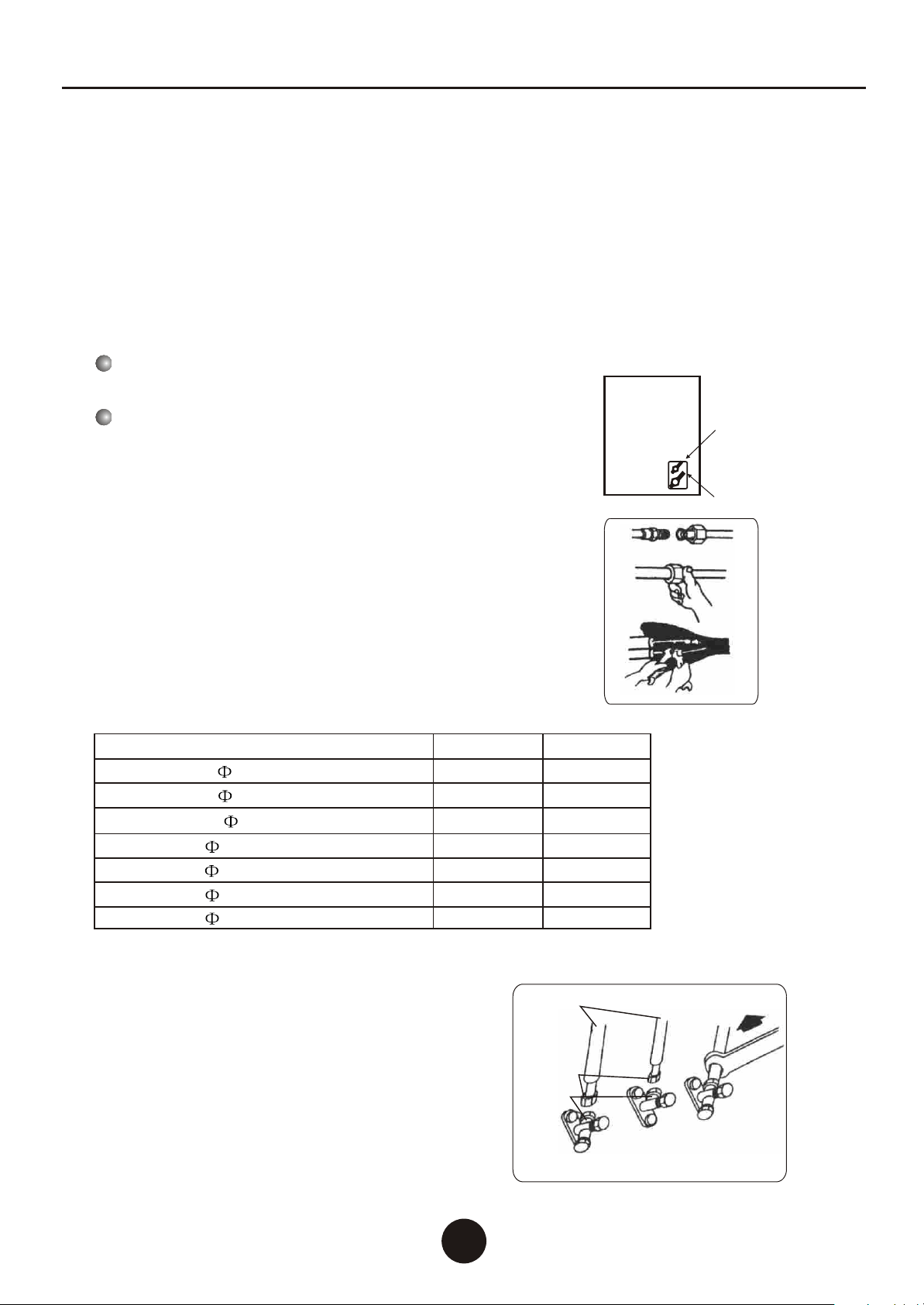
2.1 Refrigerant pipe connecting
2. The refrigerant piping connection for split type unit
b. Pre-tighten them with fingers at first, then use the wrenches.
a. Connect indoor unit pipes with two wrenches. Pay special
attention to the allowed torque as shown below to prevent
the pipes, connectors and flare nuts from being deformed
and damaged.
Piping Connection:
Pipe size
Liquid Side ( 6.35 or 1/4 inch) 1.8kg.m 17mm
22mm
24mm
22mm
27mm
3.5kg.m
3.5kg.m
5.5kg.m
7.5kg.m
Liquid Side ( 9.52 or 3/8 inch)
Gas Side ( 12.7 or 1/2 inch)
Gas Side ( 9.52 or 3/8 inch)
Gas Side ( 15.88 or 5/8 inch)
Torque Nut width
Gas Side ( 19.05 or 3/4inch) 30mm
9.5kg.m
2.1.1.The indoor unit refrigerant pipe connecting
According to the indoor and outdoor unit fixed location and location of holes through the wall, choose a
good direction lead to pipe. Then begin the indoor pipe connection work.
Screw off the nut from the valve body indoor unit,
remove the pipe head plug.
1. When tightened, first press the trumpet
on the connector cone, and keep the out pipe
and connection pipe in the same axis;
2. Gradually use hand to tighten the flare nut in
clockwise, and then use the wrench to tighten.
3. When use a wrench to tighten joints, according
to the moment shown in the following table, if not
tight it will leak, spin too tightly, may damage the trumpet.
Connect the indoor unit and pipe joints
1. Use a wrench to remove the outdoor high and
low pressure valve bonnet;
2. Remove the connection pipe's plastic head;
3. As shown on the right, press the trumpet on the
connector cone, then hold the connection pipe
with one hand, so that keep the connector axis
in the first line, the other hand the gradually
screw the flare nut on the connector, then
tighten with wrench.
2.1.2.Outdoor pipeline construction
Connected the indoor unit and outdoor unit through two matched cooper tubes, one small and
one larger. And the system should be emptied after connection, so opened the 1 / 4 laps of outdoor
unit valve for 5-10 seconds, and then close it, open the large valve needle valve to discharge air in
the indoor unit and the pipe, or vacuum it with a vacuum pump, and then close the needle valve;
check the connection part if leak, confirmed without leaking, then open all the outdoor unit large
and small valve, so that the whole system recycle work, detailed operation as follow.
High pressure valve
Low pressure valve
Tubule
Line Pipe
Connecting pipe
adapter
connector
flare nut
Gas tube
Liquid tube
Liquid Side ( 12.7 or 1/2 inch) 5.5kg.m 24mm
Air To Water Heat Pump Water Heater
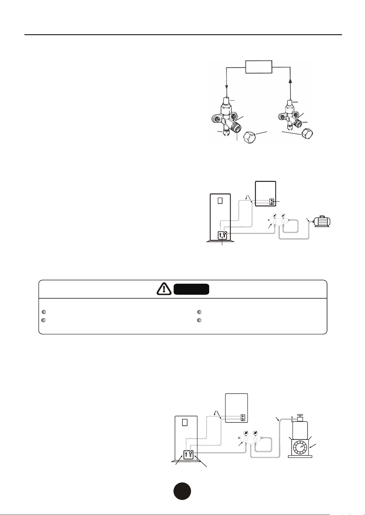
2.1.3.Air discharge (vacuum)
If the system is small, use refrigerant empty way to discharge the pipe and indoor unit air, as
the following steps:
1. Remove the high-pressure valve and low pressure
valve bonnet;
2. Remove the low-pressure valve exhaust nut;
3. Release the high-pressure valve spool 1 / 4 lap;
4. Open low-pressure valve exhaust spool,
exhaust to 15-30 seconds;
5. Tighten the low- pressure valve exhaust nut;
6. Screw the high-pressure valve and
low- pressure valve spool to the end;
7. Tighten the spool cap.
If the system large or after maintenance of outdoor system, should use the vacuum pump
discharge way to empty the air and water within the system, shown as below:
1. Screw off the outdoor unit low-pressure valve's
repair connector nut, connected the compound
pressure gauge to repair connector;
2. Connect the vacuum pump to the compound
pressure gauge, open the compound pressure
gauge and vacuum pump to vacuum the indoor
unit and pipe, so that the absolute pressure
not higher than 130Pa, and keep the pressure
does not rise within 5 minutes after vacuum.
3. After vacuum, turned on the outdoor high and
low pressure valve stem, inject the refrigerant
into the indoor unit.
Thoroughly discharge the air and moisture within the cooling system
if the air and moisture remained in the cooling system, appear the following adverse effects:
System pressure increases. Cooling (or heating) effect decreased.
Moisture will freeze plug the cooling system. Moisture can rust some parts of the
cooling system.
AttentionAttention
Valve
Valve
Copper
pipe
Outdoor unit
Indoor unit
Vacuum pump
Low pressure
side gauge
High pressure
side gauge
Hose
Composite table
2.1.4.Add refrigerant
The outdoor unit already with refrigerant before delivery, but when the pipe is too long,
please add additional refrigerant as following formula:
Additional refrigerant amount= (one-way tube length -5) x (0.015-0.02) kg, choose 0.015-0.02
according to the size of diameter. When the tracheal diameter = 12.7, choose 0.015; when the
diameter = 15.88, choose 0.02 .
Indoor unit Exhaust when refrigerants
Flow direction
Tubule
Low pressure valve High pressure valve
Line Pipe
Spool
Spool cap
Spool
Exhaust nut
The methods to add refrigerant
refer to the diagram bellow:
Indoor unit
Outdoor unit
Low-pressure valve
(suction valve)
High-pressure valve
(exhaust valve)
Low pressure
side gauge
High pressure
side gauge
Hose
Scale
Refrigerant charge tank
Piping
Composite table
66
Air To Water Heat Pump Water Heater

77
After discharge the air, use electronic leak detector or soapy
water to test all the connectors in the indoor and outdoor unit.
2.1.5.Leak check
First use hex wrench closed the high-pressure valves (1/2 ") of the unit, and then start hot
mode; after the compressor start-up , check the low pressure gage , when the pressure is close
to "0" , close the low-pressure valve (3/4 ")quickly , turn off the unit at the same time. the
refrigerant recovery will take about 25 seconds.
3. Refrigerant recovery method
4.Water Pipe connection
4.1 Pipe should be a kind of pipe that heat-resistant,rust-proof, uneasy-fouling.and in conformity
with national health and safety standards, which can be stainless steel pipe, copper pipe,
aluminum water pipe, hot water PPR pipes and so on.
4.2 Water tank outlet pipe and overflow pipe is better to installed around the gutter or sewer,
so that to convenient to drainage.
4.3 The connection of the heat pump unit and water tank must be installed a stop valve or
dismountable loose joint, for maintenance use.
4.4 Water pipes are arranged reasonably to minimize bending and reduce the pressure loss of
water system .
4.5 The connection of tap water pipe and water filling connection must install one-way valve,
filter, supply water solenoid valve (for tank-type water tank) and pressure relief devices
(for close-type valve the parameter value is 0.7MPa), installed when valve body arrow is
same as with the flow direction to prevent water block. The cycle water outlet of the heat
pump unit should connect to the inlet of water tank , The cycle water inlet of the heat pump
unit should connect to the outlet of water tank, the water supply inlet of the tank should
connect to the heat water supply outlet . The entire piping system should be clean, no rust
and dirt residue to prevent pipe blockage.
4.6 After the installation of the water filling pipe and cycle water pipe and hot water supply pipe ,
all the pipes should take the water tightness test. And ensure that the system is clean. and
then cover insulation on the pipe and valve (including the supply water pipes and valves).
4.7 For the metal pipe, must be used above 50mm thickness of glass fiber or high-density fire-
retardant PE foam to protect (PPR hot water pipe can use 30mm thickness of glass fiber or
high-density fire retardant PE foam for thermal insulation).
4.8 the unit water inlet and outlet must fit with thermometer, water pressure gage, to facilitate
inspection when operate.
Note: 1. tubing pipeline should be separate test pressure, must not test with heat pump unit
or tanks.
2. The water system working pressure: 0.2-0 .6 MPa.
3. The water system operating temperature: 5~75 .
5. Electric wiring
5.1 Unit supply cable must be used copper. Power supply voltage in line with the rated
voltage and the rated current.
5.2 The unit, power supply circuit must have a grounding wire, and the power supply ground wire
must with the external grounding wire, and an external grounding wire to be effective.
5.3 W must be installed by professional technicians carried out in accordance
with circuit.
5.4 S up a good leakage protection devices
should be
connect to
iring installation
etting and in accordance with the relevant national
technical standards.
Air To Water Heat Pump Water Heater
Power supply
PCB
Compressor
Unit
12
6.2 Specification Table of Electrical Wire
Power supply installation condition: The touching space of breaker should be more than 3mm,
must use copper wire only.
within 5m
2.0
3.5
5.5
8.0
Within 10m
2.0
3.5
5.5
8.0
14.0
Within 15m
2.0
3.5
5.5
8.0
14.0
22.0
Within 20m
3.5
5.5
8.0
14.0
22.0
30.0
Within 30m
5.5
8.0
14.0
22.0
30.0
38.0
50.0
Within 50m
8.0
14.0
22.0
30.0
38.0
50.0
60.0
80.0
Within 1m
2.0
3.5
5.5
8.0
14.0
Starting current
(A)
Below 20
Below 30
Below 40
Below 50
Below 60
Below 70
Below 80
Below 90
Below 100
Below 110
Below 120
Below 140
Below 160
Below 180
Below 200
Below 220
Below 240
Mark (Heat resistance temperature above 60 )
The wiring specifications (mm2)
Mark (Heat resistance
temperature above120 )
6.1 Voltage drop may occur due to the large current draw during compressor starting, and may be
result in the compressor is difficult to stat. So we recommend selecting the wire specification from
the table below.
6. Selection of Electrical Wire
88
5.5 Power line and signal line layout should be neat, rational, strong and weak lines separating
cable and Can not interfere with each other, without contact with the connecting pipe and
valve.
5.6 he construction of all wiring is completed, carefully check the correct order to connect
the power.
5.7 Unit electric wire connection: connect to the appropriate terminals according to wiring diagram,
and fix it by the pressure line of board in the electrical box.
5.8 All the wiring construction is completed, can be plugged in only after careful examination
correctly.
5.9 Unit control board fuse parameters: 5A/220V.
5.10 The unit wire controller must be fixed in the bottom of standard electrical switch box.
After t
Air To Water Heat Pump Water Heater
6.3 Caution of Ground
The internal motor protector does not protect the compressor against all possible conditions.
Please be sure that the system utilizes the ground connection when installed in the field.
6.4 Warning:
To avoid fire, electric shock and other accidents, keep in mind about these tips:
6.4a Only use power supply voltage indicated on the label, if you do not know the family of voltage,
contact the dealer or local power company.
6.4b When you use the unit by the maximum current please view the specifications, so make sure
your home's power supply (current, voltage and cable) to meet the machine's normal load
requirements.

6.4c To protect the power lines. Power lines should be fixed, so that people will not be trip over or
the lines damaged by other things. Paying particular attention to plugs, which should be easily
plug into the socket, careful the plug position.
6.4d Do not overload wall plugs or extension the cable. Line overload can cause fire or electric
shock.
6.5e To ensure your safety, you must plug the power lines into the socket with a grounded
three-phase, and check to ensure your socket is accurate and reliable grounding.
99
Air To Water Heat Pump Water Heater
7.Trial operation(should be operated by professionals)
7.1 Check before trial operation
7.1aCheck the pipe system. Check the whole pipe system. Ensure the water volume in the system
is full and the air is exhausted completely. Check whether the valve is open throughout the
system and the thermal insulating of the pipe is well.
7.1b Check the power supply and distribution system. Check whether the power supply voltage is
normal, the power distribution accessory screws all tighten, supply power is in compliance
with the wiring diagram and the wire is grounded well.
7.1c Check the air cooled water chiller. Check whether any screw loose. Check the signal indicator
light(green) of the outdoor unit control panel is illuminated normally and the fault indicating
lamp(red) is illuminated. Connect the pressure gauge to the freon feed mouth for checking the
pressure during operation. Disconnect them after test is ok.
7.2 Trial operation
7.2a Turn on the circulating water pump by remote control(refer to IV Use ) and check whether
the water pump operates normally. Observe and determine whether air pipe is exhausted
completely, flow switch is closed, hydraulic pressure indicated in the pressure gauge is more
than 0.2MPa.Come to next step after confirm the circulating water system works normally.
7.2b Press on/off in the remote controller, the water pump and fan start immediately.
The compressor start after the unit operates for some time. Observe and determine if there s
any abnormal sound during operation. Stop to check the unit if there s abnormal sound. The
unit can continue to run only when there s no abnormal sound. Check whether the cooling
system pressure is normal at the same time.
7.2c Check whether the input power and current of the unit are compliance with the parameter in
this Instruction. If not, stop to check the unit.
7.2d Observe whether the outlet water temperature is normal.
7.2e Parameter of the remote controller has been set before leave of the factory. Never alternate
them personally.
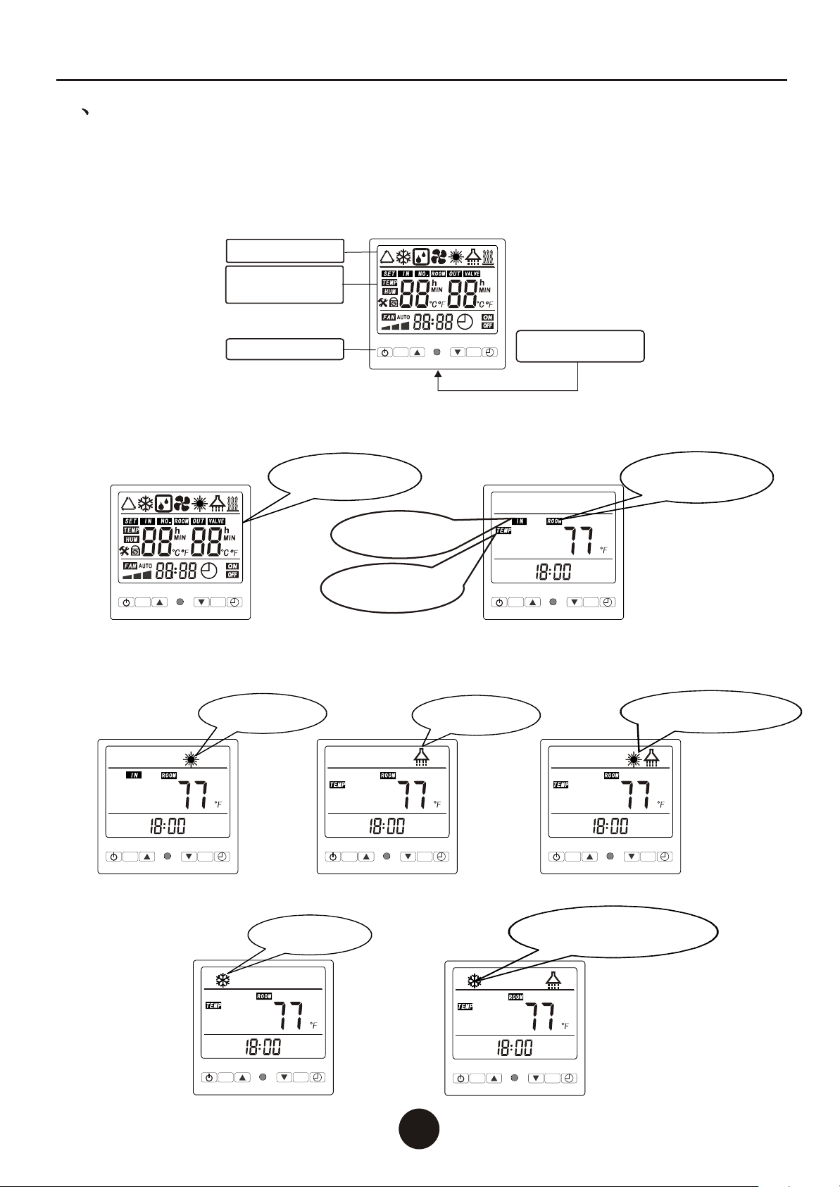
button operate
operate mode display
1.Function diagram of the remote controller.
2.Use of remote controller
The remote controller is designed and employed standard electrical box dimensions(86*86,fixed hole
distance 60mm). The electrical box and three core can be built in the wall before decoration, which makes
the interior decoration more perfect. The user interface and function shows as below:
operate status,
parameter setting display
2.1 Initial power on and stand by status: Power on after check and confirm the unit is normal. The remote
controller will be full-screen display. The main unit will be on stand by status 10 seconds later . Distance
will display the standby.
1010
2.2 Under boot-up status ,press ' M' button to switch therunning mode , when the parameter 22 isset be '0 '
to switch off the cooling function, so theunit will has 3modes at that time :1. air heating mode 2. domestic
hot water mode 3. Air heating and domestic hot water mode.
SETSET
MM
1
2
%%
SETSETSETSET
MM
1
2
%%
2.3. when the parameter 22 is setbe '1 '(that means switch onthe cooling function), there will be more
the following 2 modes, and you also canpress ' M 'to switch the modes.
Initialization mode Indoor environment
temperature icon
III UseIII Use
Air To Water Heat Pump Water Heater
Water inlet
temperature icon
Indoor environment
temperature sensor
SETSET
SETSET
Hot water tank
temperature icon
Domestic hot
water mode
Air heating and domestic
hot water mode
SETSET
Air colling mode
SETSET
Air colling and domestic
hot water mode
SETSET
Air heating mode
MM
MMMMMM
MMMM
SETSET
1111
2.4 Clock setting. Press button , the place of hour keeps flicking, press to
adjust the setting of hour . Then press button and the place of minute will keep flicking .
Press the button to adjust the setting of minute. Press button again to
complete and exit the time setting mode.
SETSET
SETSET
2.5 Timed ON/OFF setting. Press botton,and the of place hour and 1 Timing ON
symbol keep flicking. Press to adjust the setting of the hour. Press button
again,and the bit minute flicks. Press buttons to adjust the setting of minute; Press
button again and the place of hour and timing OFF symbol flicks. Press to
adjust the setting of hour. Press button again, and the bit minute flickers. Press
buttons to adjust the setting of minute. Press botton,and the of place hour
and 2 Timing ON symbol keep flicking. Press to adjust the setting of the hour.
Press button again,and the bit minute flicks. Press buttons to adjust the
setting of minute; Press button again and the place of hour and timing OFF symbol
flicks. Press to adjust the setting of hour. Press button again, and the bit
minute flickers. Press buttons to adjust the setting of minute. Press button
again to complete and exit the timed ON/OFF setting mode. Cancel timing setting operation.
press button and press button to cancel the timing
SETSET
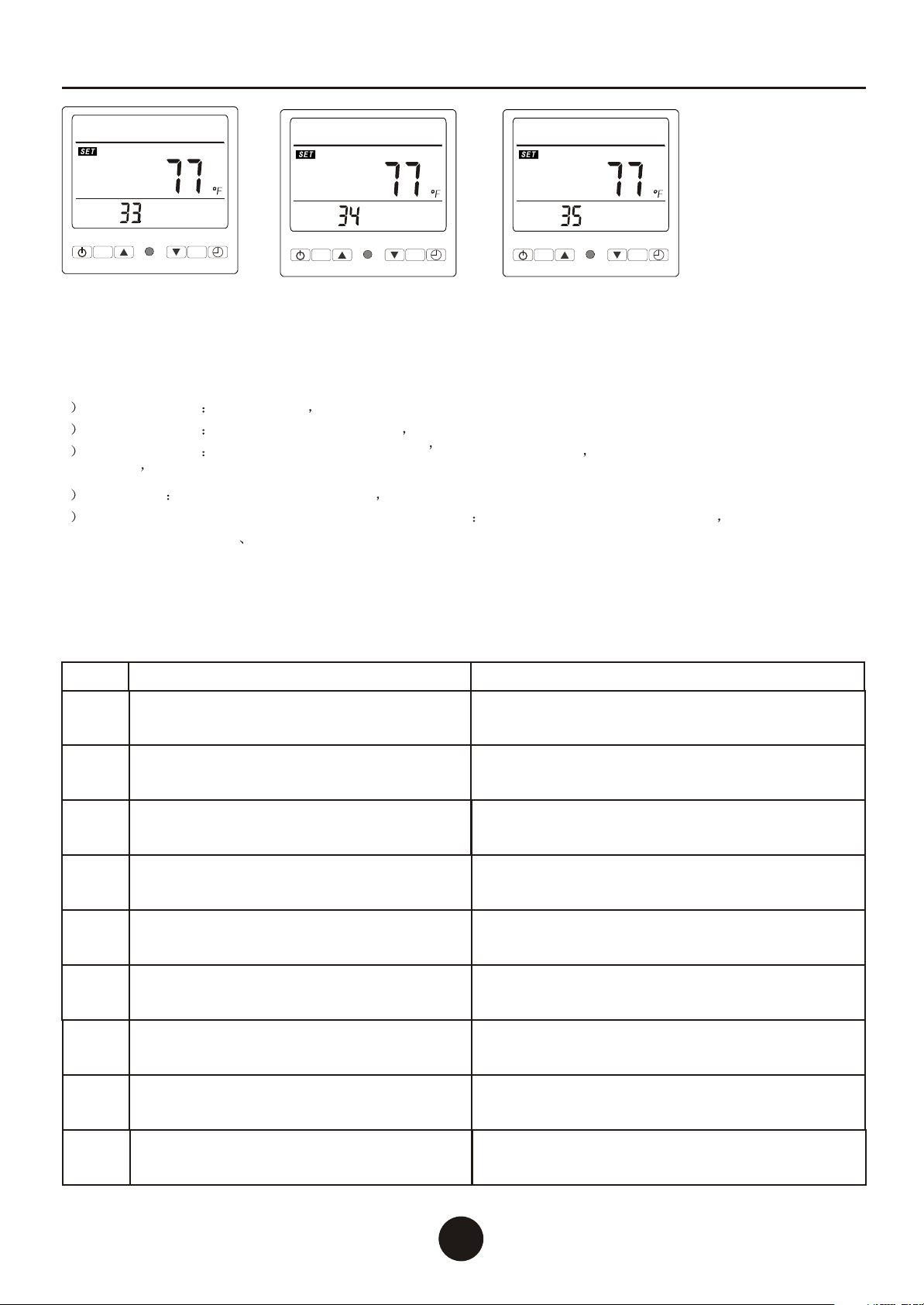
2.7 These settings are for Engineers only, please call if you require to change any of the Optional
Parameters. Under the power on or standby status, press buttons at the same time for
10 seconds to enter Operation Parameter setting interface. Press or to view
01-36 parameter,press button again to set data you need. Parameter setting as below:
SETSET
SETSET
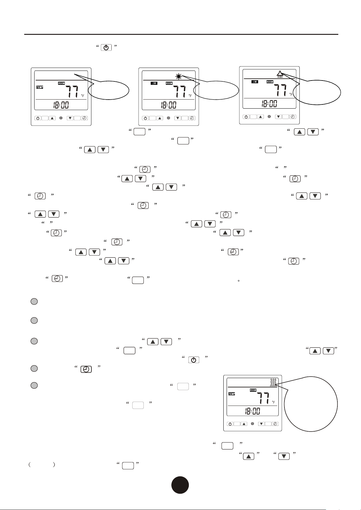
2.3 Power on/off: Press button to start the unit, Then the LCD will display the current mode and
two temperature value(Both different kinds of temperature value will display 5 seconds each on the
interface,one after one to display automatically .)
Air To Water Heat Pump Water Heater
SETSET
MM
Standby state
SETSET
MM
working state
Note:
The Timing function only can be used under the parameter 26 is set be ''1' ,otherwise, there's
no the timing function.
Domestic water tank temperature and indoor environment temperature, and can be modified
under standby state or working state, others can be modified under standby state.
In the working state, press the buttons can set up the user common use setting
parameters ,press the buttons to switch to modified parameters, press
button to modify the parameters,press the buttons,exit the setting interface.
1
2
3
SETSET
4
5
press the button for 5 seconds to switch the display between centigrade degree and
fahrenheit.
SETSET
MM
Icon constantly flickering,
enter into manual electrical
heating output mode.
When boot-strap and on standby, press button
for 5 seconds for the manual operation electric heater
heating output, press the button for 5 seconds
again,shutdown the manual operation electric heater
heating output
MM
MM
Icon do not twinkle,enter
into automatic electric
heat output mode.
SETSET
MM
Keep falsh
Defrost state

SETSET
MM
SETSET
MM
SETSET
MM
SETSET
MM
SETSET
MM
SETSET
MM
SETSET
MM
SETSET
MM
SETSET
MM
SETSET
MM
SETSET
MM
SETSET
MM
SETSET
MM
SETSET
MM
SETSET
MM
SETSET
MM
Parameter 05
hot water temp.
difference between the unit stop
heating and restartheating
Alternative range: 2 to 30 .
Default: 10
Domestic
Parameter 06
Cooling return water temp.
difference between the unit stop
heating and restartheating .
Alternative range: 2 to 30 .
Default: 10
Parameter 07
Heating return watertemp.
difference between the unit stop
heating and restartheating .
Alternative range: 2 to 30 .
Default: 10
Parameter 08
Room temp. difference
between the unit stop heating
and restart heating .
Alternative range: 2 to 30 .
Default: 4
1212
Air To Water Heat Pump Water Heater
Parameter 01
Alternative range:
50 to 158 .
Default: 131
Domestic hot watertank
temperature setting
Parameter 02
Air cooling
Alternative range:
46 to 82 .
Default: 54
return water
temperature setting
Parameter 03
Air heating returnwater
temperature setting
Alternative range:
59 to 140 .
Default: 104
Parameter 04
Room temperature setting
Alternative range:
50 to 113 .
Default: 77
Parameter 09
Alternative range:
30minutes to 90minutes.
Default: 40minutes
Heating defrost cycle
Parameter 11
Alternative range: 36 to 86 .
Default: 55
Exit defrost temperature.
Parameter 12
Alternative range:
1 minutes to12 minutes.
Default: 8 minutes
Exit defrost timecondition
Parameter 10
Alternative range: -86 to 32
Default: -45
Into defrost temperature
Parameter 13
Single or double
1 is single system,
2 is double system
Default: 1
system
selection.
Parameter 14
1:with memory function
2:without memory function
Default: 1
Whether power-down memory
Parameter 15
wire cotrol sensor or the
:wire control sensor
0:multi-room switch
Default: 1
multi
-room switch Selection.
1
Parameter 16
W
:Turn off
1:Turn on
Default: 1
hether turn on automatic
electric heating function.
0

SETSET
MM
SETSET
MMSETSET
MM
SETSET
MM
SETSET
MM
SETSET
MM
SETSET
MM
SETSET
MM
SETSET
MM
SETSET
MM
SETSET
MM
SETSET
MM
1313
Air To Water Heat Pump Water Heater
Parameter 18
0:long time workingfor water
pump
1:water pump turnsoff after
the whole unitpower offfor 30s
Default:1
Parameter 19
Alternative range: 140 to 194
Default: 140
(The unit havecancled the high-temperaturedisinfection )
High-temperature disinfection
per week setting,
Parameter 20
Alternative range: 10~90Min.
Default: 30Min.
High-temperature disinfection
maintain time,
Parameter 17
0:
: Air
Default: 0
Domestic hot waterpriority,
or heating andcooling priority
Domestic hot waterpriority
1 heating and aircooling
priority
Parameter 21
The room temp. difference setting
between non-sleeping status mode
and sleeping status mode
Alternative range: -30 to 30 .
Default: 10
Parameter 22
Whether turn on air cooling
function model
0: turn off
1: turn on
Default: 0
Parameter 23
The start timeof non-sleeping
status mode.
Default: 05:00
Parameter 24
The end timeof non-sleeping
status mode.
Default: 23:00
SETSET
MMSETSET
MMSETSET
MMSETSET
MM
Parameter 27
Actual testing value:
Living hot watertank
temperature
Domestic hot watertank temp.
Parameter 28
water return temp.
Actual testing value:
Unit inlet watertemperature
Parameter 29
water outlet temp.
Actual testing value:
Unit outlet watertemperature
Parameter 30
Indoor environment temp.
Actual testing value:
Indoor environment
temperature
Parameter 31
Out door environmenttemp.
Actual testing value:
Outdoor environment
temperature
Parameter 32
Pipe temp.1
Actual testing value:
pipe temperature (system1)
Parameter 25
The temp. difference setting
between solar temp. and water tank
temp. for turn on the water pump
Alternative range: 2 to 40
Default: 12
Parameter 26
whether turn on the timing function
0: Turn off
1: Turn on
Default: 0
1414
Air To Water Heat Pump Water Heater
SETSET
MMSETSET
MMSETSET
MM
Parameter 34
Exhaust 1 temp.
Actual testing value:
exhaust temperature (system1)
Parameter 35
Exhaust 2 temp.
Actual testing value:
exhaust temperature (system2)
Parameter 33
Pipe temp.2
Actual testing value:
pipe temperature (system2)
Remark :
1 Parameter value 13 1:single system 2:double system
2 Parameter value 14 0: without power-down memory 1: with power-down memory
3 Parameter value 15 0: uncontrolled by the wire controller s temp. sensor function 1: controlled by the wire
controller s temp. Sensor function
4 Parameter 16 0: without electric heater auxiliary 1: with electric hear auxiliary (efficient for the unit with electric heater auxiliary )
5 Water pump working way introductions for the parameter value 18 0:starts 10 seconds before compressor stops 30
seconds after compressor 1:always open
3:Operation data setting
The unit's operation data can be set on the wire controller.
Please set according to the table below.
Parameter
NO . meaning explanation of parameters
01
Domestic hot water tank temperature
setting
02
Air cooling return water temperature
setting
03
Air heating return water temperature
setting
This parameter fortank temp. canbe set bythe up and down
arrow buttons byuser under boot-state.
04
Room temperature setting
This parameter forhot water inlettemp. can controlthe compres
-sor ON/OFF whenworking the coolingmode.
This parameter for hot water inlet temp. can control the compres
-sor ON/OFF whenworking the heatingmode.
05
Domestic hot water temp. difference
between the unit stop heating and restart
heating
06
Air cooling return water temp.difference
between the unit stop heating and restart
heating .
07
Air heating return water temp.difference
between the unit stop heating and restart
heating .
08
Room temp. difference between the unit
stop heatingand restart heating .
09
Heating defrost cycle
This parameter can set the roomtemp. and control the floor
heating water pumpON/OFF by the up and downarrow keys on
the wire controller.
This parameter isused for re-heating the water after
and in hotwater mode by means of setting how many
temp. value ofthe hot water tank has been decreased .
thermostat
stop heating
This parameter isused for re-cooling the water after
and in coolingmode by means of setting how many
temp. value ofthe inlet water temp. has been rise.
thermostat
stop cooling
This parameter forre-house heating after
and in heatingmode by means of setting how many temp.
Value of the inlet water temp. has been decrease .
thermostat stop heat-
-ing
This parameter forre-working floor heating/cooling water pump
after by means ofsetting how
many temp. valueof the room temp. has been decrease/rise .
thermostat stop heating/cooling
Period setting forunit cycle defrost

1515
Air To Water Heat Pump Water Heater
10
Into defrost temperature setting.
11
Exit defrost temperature setting.
12
Exit defrost time condition setting .
13
Single or double system selection.
14
Whether power-down memory .
15
Wire cotrol sensor or the" multi-room
switch" Selection.
16
W
hether turn on automatic electric
heating function.
17
Domestic hot water priority, or heating
and cooling priority .
18
Room temp. difference between the unit
stop heating and restart heating .
19
High-temperature disinfection per week
setting .
20
High-temperature disinfection maintain
time.
21
The room temp. difference setting
between non-sleeping status mode
and sleeping status mode .
22
Whether turn on air cooling function
model .
23
The start time of non-sleeping status
mode .
24
The end time of non-sleeping status
mode .
25
The temp. difference setting between solar
temp. and water tank temp. for turn on the
water pump .
26
Whether turn on the timing function.
The coil temperaturesetting for enter into defrost status
The coil temperaturesetting for exit the defrost status.
The maximum runningtime for defrost state.
Setting for dualsystem selection.
This parameter isused for setting whether keep the original
operation statues afterunit power off and restart.
This parameter isused for setting whether use the sensor on wire
controller or usethe multi-room switch to control the room temp-
-erature.
This parameter isused for setting whether turn on automatic
electric heating mode.If ON, there's electric heating after the
compressor running for1 hour.
This parameter isused for setting whether priority turn on the
heating water modeor priority turn on the cooling water mode.
This parameter iscycle water pump operation setting. whenin hot
water mode, setit constant temperature closing is thebest, when in
cooling or heatingmode, set it constant temperature startingis the
best.
This parameter iswhether to open the cooling mode to the user.
Press the 'mode'button to set it ON/OFF.
This parameter isthe start time setting for the non-sleep period.
The unit hascanceled the high temp.sterilization function
The unit hascanceled the high temp.sterilization function
The unit hascanceled the high temp.sterilization function
This parameter isthe ending time setting for the non-sleep period.
This parameter isthe temperature difference setting between
solar collector temp.and the water tank temp. , this setting is
used for controlthe solar pump ON/OFF.
This parameter isthe setting whether open the timing function to
user for theuser.

Wire
Controller
Wire
Controller MalfunctionMalfunction
1.Malfunction Indicating Table. Determine and solve the malfuction by malfuction code as below:
1.1.operate display fault code mode
1616
E01
E02
E03
E04
E05
E06
E07
E08
E09
E10
P01
P02
P03
P04
P05
P06
P07
P08
P09
P10
P11
P12
ReasonReason ResolutionResolution
Check or change the sensor
Check or change the sensor
Check or change the sensor
Check or change the sensor
Check or change the sensor
Check or change the sensor
Check or change the sensor
Check or change the sensor
Check or change the sensor
The sensor is open or short circuit
Water inlet temp. Sensor failure
Water outlet temp. Sensor failure
System 1discharge sensor
failure
System 1 pipe sensor failure
System 2 Pipe sensor failure
Indoor environment temp.
Sensor failure
Outdoor environment temp.
Sensor failure
The sensor is open or short circuit
The sensor is open or short circuit
The sensor is open or short circuit
The sensor is open or short circuit
The sensor is open or short circuit
The sensor is open or short circuit
The sensor is open or short circuit
The sensor is open or short circuit
High pressure 1
switch protection
High pressure 2
switch protection
Low pressure 1
switch protection
Low pressure 2
switch protection
Flow switch 1 protection
Flow switch 2 protection
system 1 high pressure
protection
system 1 low pressure
protection
system 2 high pressure
protection
system 2 low pressure
protection
3 times of excessive temp.
differentials of inlet water
and outlet water in 30minutes
Water flow volume not enough,
water pressure difference is too low
Check the water flow volume,
or water system is blocked or not.
Communication failure
Wire controller and The
PCB connection failure. Check the wire connection
No water/little water
in water system.
Check the water flow volume,
water pump is failure or not.
No water/little water
in water system.
Check the water flow volume,
water pump is failure or not.
Check whether the pressure switch
and system return route failure.
Check whether the pressure switch
and system return route failure.
Check whether the pressure switch
and system return route failure.
Check whether the pressure switch
and system return route failure.
Tank temp. Sensor failure
Phase failure protection
electric heater auxiliary overheating
& dry heating protection
Frost-protection
High discharge 1 temperature
protection
High discharge 2 temperature
protection
Power supply phase failure /lacking
Check whether power supply phase failure or
lacking, if failure, please connect it in according
to the proper way.
when the outdoor temp. below 0
under standby model
after the antifreezing procedure ,unit will
return to the original state automatically
Check the over heating switch normal or not
The protector open circuit or
short circuit
1.whether gas of system leak or not
2.the tank temp. Be set too high
1 check the refrigerent amount inthe system
2 check whether the tank temp.Setting value too high
1.whether gas of system leak or not
2.the tank temp. Be set too high
1 check therefrigerent amount in the system
2 check whether the tank temp. Setting value too high
IV Maintenance and repairIV Maintenance and repair
Air To Water Heat Pump Water Heater
System 2 discharge sensor
failure

1717
1 The choice of installation ways
1.1 the installation way for domestic hot water model
TankTank
house hot
water area
Tank temperature
Remark :
1) In the working state, press the buttons can set up the parameters 1 , at this time you can adjust the
setpoint of the water tank temperature,press the buttons, exit the setting interface.
2) Circulating water pump working way introductions for the parameter value 18:
0:starts 10 seconds before compressor
stops 30 seconds after compressor
1:always open
3) The port of 29 30 on PCB should connect to the water tank to detect the tank temp.
Cycle water out
Drain out
Hot water out
Cold water in
Cycle water in
Wire controller
Hot water tank temp.
Disconnecting valve
One way-valve
The parameter setting for domestic hot water model:
01 50 ~140 131 Adjustable
05 2 ~30 10
Digit Meaning Range Default Parameter setting for
domestic water mode
18 0/1 10
Adjustable
Domestic hot water tank temperature setting
Circulating water pump works option
Domestic hot water return temperature
V Installation sketchV Installation sketch
Air To Water Heat Pump Water Heater
POWER INPUT
(208~230V)
PCBPCB
L1 L2
29 30
01 02 03
L1 L2 L1 L2 L1 L2 L1 L2 L1 L2 L1 L2
PUMP
Outdoor fan
(208~230V)
Auxiliary electric
heater
(208~230VAC)
Solar cycle
pump
(208~230VAC)
Cycle water
pump 1
(208~230VAC)
Electric three-way
valve
(208~230VAC)
Cycle water
pump 2
(208~230VAC)
This manual suits for next models
15
Table of contents
Popular Water Heater manuals by other brands


Vaillant
Vaillant VPS R 100/1 M Operating and installation instructions

Cooper & Hunter
Cooper & Hunter CH-HP3.5SWNK owner's manual

Solarbayer
Solarbayer HSK-SLS Product information

Rommelsbacher
Rommelsbacher RT 350 instruction manual

Eccotemp
Eccotemp 20 Series Use & care manual

PVI Industries
PVI Industries COBREX Installation & maintenance manual

Intellihot
Intellihot i200X Operation manual

3P Technik
3P Technik 3P Barrique instruction sheet

Poloma
Poloma PH-28 C DVSN Installation and operating instruction manual

A.O. Smith
A.O. Smith T-H3J-DV Service manual

TLV
TLV SteamAqua SQ10 instruction manual

Maxwell
Maxwell MSxxxC2T series Installation and instruction manual