Healt o meter 402LB User manual

P/N UM402LB REV20190501 2
Health o meter®Professional 402LB
Thank you for your purchase of this Health o meter®Professional product. Please read this
manual carefully, and keep it for easy reference or training.
TABLE OF CONTENTS
Cautions and Warnings.............................................................................................3
Specifications for This Scale.....................................................................................4
Certifications / Disposal / Service..............................................................................4
Assembly Instructions ...............................................................................................5
Operating Instructions...............................................................................................7
Height Measurement Instructions..............................................................................9
Transportation ..........................................................................................................11
Troubleshooting ........................................................................................................12
Maintenance and Cleaning........................................................................................14
Warranty....................................................................................................................15
Note: This scale has been factory calibrated, and does not
require calibration prior to use.
Please register your scale for warranty coverage at:
www.homscales.com
For User Instructions updates and revisions please go to:
www.homscales.com

P/N UM402LB REV20190501 3
CAUTIONS AND WARNINGS
INTENDED USE
This Health o meter®Professional platform scale is intended to be used in a professional medical
environment by trained medical staff. This product was designed to weigh patients who are safely
positioned and standing on the platform. The intended use of the built-in height rod is to measure
patient height. Do not modify the product or use it for anything other than its intended purpose.
To prevent patient/caregiver injury or damage to your scale, please follow the
instructions in this user manual very carefully.
Do not exceed the specified weight limit for this scale.
Do not transport the scale with a patient or object on the scale.
Do not wheel or pull the scale down stairs, doing so may damage internal parts.
To prevent injury, as well as scale damage during assembly, exercise caution when
assembling the scale pillar.
Assemble and operate the scale per the enclosed user instructions.
For accurate weighing, this scale must be placed on a flat, stable surface.
For accurate weighing, verify before each use the proper operation according to the
procedure described in this manual.
Do not use in the presence of flammable or explosive materials.
If the scale becomes damaged, it should not be operated until properly serviced.
Patient/caregiver safety
This scale is designed for static weighing of patients only. No scale should be used for
patient transfer.
Patient should wear socks or other form of lightweight foot covering during weighing
event.
To prevent patient injury, the patient must be attended to throughout the entire weighing
event. Caregivers should ensure that the patient is stable and provide support as
needed when getting onto and off of the scale.
In no event whatsoever shall Pelstar, LLC be liable for damages or injuries arising from
or connected with the assembly, use, or misuse of its products.

P/N UM402LB REV20190501 4
SPECIFICATIONS / CERTIFICATIONS / SERVICE
General
The Model 402LB physician beam scale employs a proven and rugged mechanical design to
measure patient weight and height. Each precision scale is designed to provide accurate,
reliable, and repeatable weight measurements. In addition, each scale is designed to provide
the user with features that make the weighing process simple, fast, and convenient.
Weight is displayed in pounds (lb). Height is displayed in inches (in) or in centimeters (cm).
Scale Specifications
Capacity:
400 lb
Environmental:
Operating temperatures: 50°F to 104°F (10°C to 40°C)
Storage temperatures: 50°F to 104°F (10°C to 40°C)
Maximum Humidity: 85% RH
Physical Dimensions:
Scale (Overall Dimensions)
Width: 16-3/4” (42.6 cm)
Depth: 20-1/4” (51.4 cm)
Height: 57-1/2 (146.1 cm)
Weight: 28 lb (12.7 kg)
Platform (Standing Area)
Width: 10-1/2 (26.7cm)
Depth: 14” (35.6 cm)
Height: 3-1/4” (8.3 cm)
Certification Descriptions
Scale Disposal
This Health o meter®Professional scale must be disposed of properly as steel
waste. Follow the national, regional or local regulations which apply to you for
disposal of steel waste.
Customer Service Information
The 402LB physician beam scale is shipped disassembled in one carton. Carefully inspect the
carton for shipping damage before unpacking. If damage is found, contact Customer Service.
For further information or telephone support, please contact Customer Service at:
Telephone: 1 (800) 815-6615
Email: homprocs@homscales.com
Pelstar, LLC has been officially certified as the manufacturer
of Health o meter®Professional medical devices. The Pelstar,
LLC quality assurance system covers the development,
production, sales and service of medical scales and
measuring systems.
Products carrying this symbol meet the requirements of:
Medical Device Directive 93/42/EEC
0459

P/N UM402LB REV20190501 5
ASSEMBLY INSTRUCTIONS
Before Assembly
Each 402LB physician beam scale is shipped disassembled in one carton. Carefully inspect the
carton for shipping damage before unpacking. If damage is found, contact your shipper or a
Health o meter®Professional representative immediately. Claims must be filed with the shipper
as soon as possible after receipt of the package. The following information details what you will
find inside the main carton as you unpack the parts for assembly.
To prevent scratching any components and avoid damaging the scale parts when unpacking, do
not use a box cutter, knife, scissors, or any sharp object to open the protective inner packaging.
Carefully remove each assembly from the carton and unwrap the packing materials. Set the
carton aside for storage.
Parts List
Carton
(1) Scale platform
(1) Pillar
(4) Pillar nuts
(1) User instructions
(1) Wrench
Tools Required
Wrench (included)

P/N UM402LB REV20190501 6
ASSEMBLY INSTRUCTIONS (CONTINUED)
Caution: It is recommended that the assembly be performed by two people. Use of a
chair is also recommended for the assembly process.
1.Carefully remove the scale platform and
pillar from the carton and place on a flat,
level, and dry surface. Locate the steel rod
at the base of the pillar. Cut the tie wrap that
holds the steel rod / finger pull loop to the
pillar.
2.Obtain a sturdy chair and place the top of
the pillar with the height rod side facing
down on the seat of the chair, as shown.
Place the platform/base perpendicular to the
platform with the front of the base resting on
the floor and the top of the platform/base
facing the top of the pillar. Align the four
studs on the bottom of the pillar with the four
holes in the top of the platform/base. Insert
the studs into the platform/base.
Note: If a chair is not available it is
recommended that one person holds the
platform/base while another person handles
the pillar.
3. Access the underside of the scale base.
Obtain the four pillar nuts in the carton and
place onto the studs on the underside of the
scale base. Using the provided wrench,
tighten the pillar nuts to secure the pillar to
the base.
4. Grasp the finger pull loop on the end of
the steel rod and pull towards the lever
extension. Push the lever extension towards
the finger pull loop. Hook the steel rod to the
hole at the end of the lever extension.
Release the finger pull loop and ensure that
the steel rod and lever extension are hooked
together. Carefully position the scale to its
upright position. The scale is now
assembled. Refer to the next page to zero
balance the scale before first use.
Tie wrap
Pillar nuts
Column B
(top)
Column B
(top)
Finger pull
loop
Steel rod
Lever
extension
Studs
Steel rod /
finger pull loop

P/N UM402LB REV20190501 7
OPERATING INSTRUCTIONS
Zero Balance Adjustment
Before first use, the scale needs to be zero balanced by following the instructions below. The scale
should also be checked and balanced periodically, particularly when moved.
Note: A flat head screwdriver is required.
1. Ensure that the scale is located on a hard, flat, and level surface. Step on and off scale several
times in order to align all internal parts.
2. Place both poise weights on the “0” value on both bars. The beam pointer should float gently up
and down, and not touch the top or bottom of the trig-loop.
3. If the beam pointer is not centered in the trig-loop opening, using a flat head screwdriver, rotate
the balance ball screw to correct the beam pointer. Turn the screw about ¼ turn forwards or
backwards and let poise bar settle. Based on which direction the poise bar moved turn ¼
forwards or backwards again and let poise bar settle until the pointer is centered in the trig loop.
Weighing Instructions
1. Set the upper and lower poise weights to indicate the patient’s approximate weight.
2. Have patient step onto the scale. Ensure they are positioned directly in the center of the
platform. Continue to adjust the upper and lower poise weights until the pointer is centered.
Note: It is not necessary for you to wait for the pointer to stop moving in order to read the
correct weight. As long as the pointer is moving equally within the trig-loop opening, the
patient’s weight can be determined.
3. To read the patient’s weight, observe the location of the indicator arrow built into each poise
weight. Read the value on the poise bar, closest to the indicator arrow.
4. For easy identification, pounds (lb) have black graduations on a silver background, located on
the poise bars.
5. Add the indicated reading of the upper poise value to the indicated reading of the lower poise
value. The total amount is the patient weight. See the example on the next page.
Note: To transport your scale, acquire the optional wheel bracket (Item # 55000). Please refer to
the “Transportation”section on page 11 for assembly instructions.
Upper poise bar
Upper poise
weight
Balance ball
screw
Lower poise weight
Lower poise bar
Pointer
Trig loop
Pillar head
Balance ball
Pillar
P/N UM402LB REV20190501 8
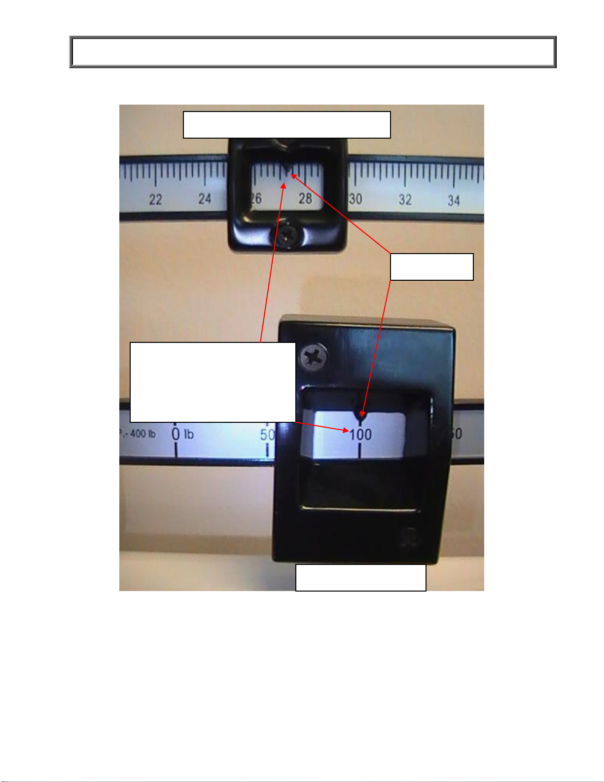
OPERATING INSTRUCTIONS (CONTINUED)
Indicator
Value reads 27.25 lb / 27 lb 4 oz
Value reads 100 lb
Combined value: 100 lb +
27.25 lb = 129.75 lb
- Or -
Combined value: 100 lb +
27 lb 4 oz = 127 lb 4 oz

P/N UM402LB REV20190501 9
HEIGHT MEASUREMENT INSTRUCTIONS
WARNING: Use caution when sliding height rod up and down. The rod should move
smoothly, do not move the rod in a jerking motion. Fold headpiece down when not in
use.
Note: A patient needs to be a minimum of 23-5/8” (60 cm) tall for height to be measured.
1. With the headpiece in the folded down
position, slide the headpiece up or down to
the estimated height of the patient. Then
raise the headpiece into its horizontal
position.
To lower height rod below 46 ⅜”, push the tab
at the top of the height rod and gently lower the
headpiece.
2. Ensure that the patient’s posture is upright,
and that the patient’s head is straight and
level. Slide the headpiece down until it rests
on the patient’s head.
3. Determine the patient’s height by reading
the value on the measuring strip nearest to
the line on the indicator, as shown on the
next page.
Push tab inward to
lower height rod
below 46 ⅜”
P/N UM402LB REV20190501 10
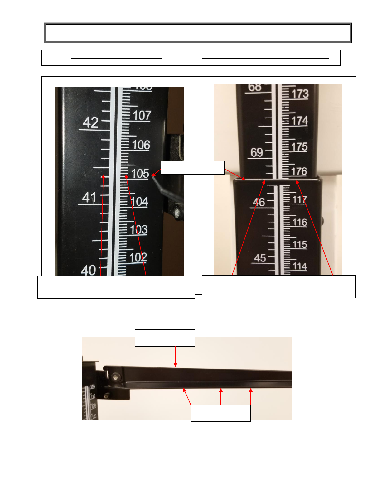
HEIGHT MEASUREMENT INSTRUCTIONS (CONTINUED)
Height Rod Below 46 3/8”
bove 46 3/8”Height Rod Extended A
Cm read: 176 cm +
0.2 cm = 176.2 cm
Cm read: 105 cm +
0.2 cm = 105.2 cm
Inches read: 41” +
3/8” = 41 3/8”
Inches read: 69” +
3/8” = 69 3/8”
Headpiece
Indicator
Indicator
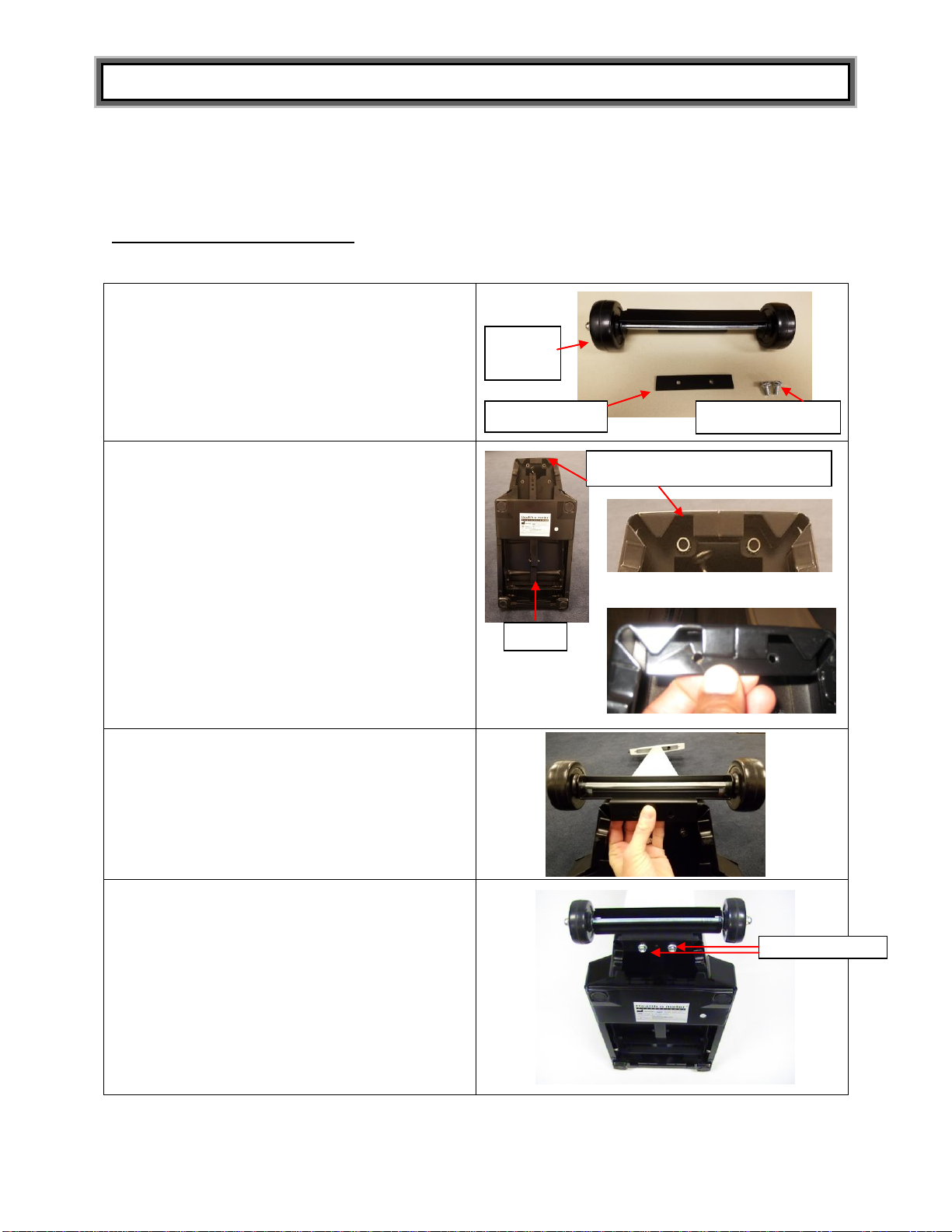
P/N UM402LB REV20190501 11
TRANSPORTATION
A wheel bracket is included if purchased as model 402LBWH. If purchased as model 402LB an
optional wheel bracket can be purchased separately (Item #55000). Follow these steps to install
the wheel bracket:
Tools Required (not included)
Adjustable wrench or 10 mm wrench
1.Remove the mounting screws that attach the
clamping plate to the wheel bracket.
2.Gain access to the underside of the scale
base by carefully tipping the scale forward
until the pillar is resting on the floor. Position
the clamping plate inside the base by
aligning the holes in the clamping plate and
base.
3.Position the wheel bracket onto the base by
aligning the holes in the wheel bracket with
the holes in the clamping plate.
4.Insert the mounting screws through the
wheel bracket and into the clamping plate.
Using a wrench, tighten the mounting screws
to secure the wheel bracket to the base.
Carefully tip the scale to its upright position.
To transport the scale, tip the pillar backwards until the scale is resting on the wheel bracket.
Carefully move the scale to its new location.
Base
Mount wheel bracket here
Close-up view of wheel mounting area
Clamping plate
Wheel
bracket
Mounting screws
Mounting screws

P/N UM402LB REV20190501 12
TROUBLESHOOTING
Troubleshooting
Before contacting service personnel, refer to the following instructions to check and to correct
any failures for incorrect weight measurements.
The accuracy of the 402LB scale when calibrated at the factory is within +/- ¼ pound. For the
most accurate weight measurement, use the scale on a hard level surface and stand in the
center of the platform. If the error seems excessive, check the following:
Symptom
Possible Cause
Corrective Action
Questionable weight, or
the scale does not
center equally in the trig
loop when the poise
weight is “0” value
Bar does not “0”
balance
The balance ball must be balanced such
that the pointer comes to rest in the center
of the trig-loop when both poise weights
are set at “0” value.
Ensure that the upper and lower poise
weights are firmly against the shoulder of
the beam.
Adjust the balance ball screw by turning
the screw at the left end of the bar.
Bar does not move
freely
Bar sticking or
adjustment needed
Check if the pointer is touching the side of
the trig loop in its range of travel.
Realignment of the beam may be
necessary if it is touching.
Ensure that the upper and lower poise
weights are firmly against the shoulder of
the beam.
Adjust the balance ball screw by turning
the screw at the left end of the bar.
Platform rocks
excessively or touches
base at any corner
Base out of alignment
Follow the base alignment instructions on
the next page.
Beam does not move at
all during weighing
process
Scale may have
improper steel rod
connection or poise
weight may have been
set at a higher weight
than patient’s actual
weight.
Reset the weights to a lower weight.
Ensure the steel rod is connected
properly; refer to “Assembly Instructions”
on page 5.
Scale not accurately
measuring weight
Scale out of
calibration.
The scale can be recalibrated by
loosening the lock screw at the end of the
long lever in the bottom of the base with a
¾” hexagon socket wrench and moving it
outward (longer) in the elongated slot to
decrease the indicated weight or inward
(shorter) to increase the indicated weight.
One sixteenth inch movement of the
screw will change the indicated weight by
approximately one-quarter pound per 100
pounds.
For further assistance please contact technical support toll free at 1 (800)-638-3722.
P/N UM402LB REV20190501 13
TROUBLESHOOTING (CONTINUED)
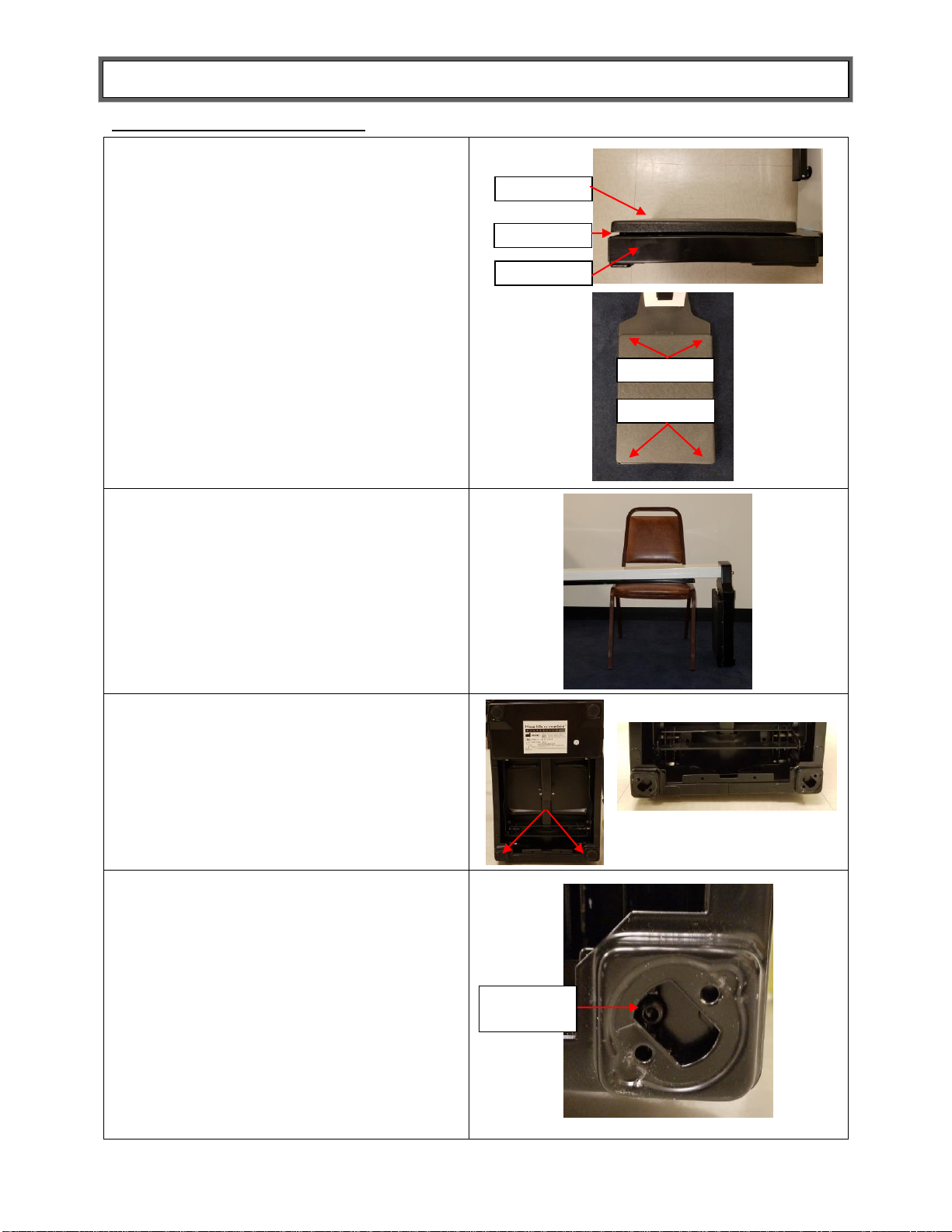
Base Alignment Instructions
1. Check the space between the platform
and the base. The space should be even
on all four sides of the base. To test if the
space is even gently press down on one
of the toe-end cornersand note the
depressed space. Press down on the
other toe-end corner and compare the
space. Do the same for all four corners to
detech which corner is higher or lower
than others.
2. To align the space between the platform
and base the hex screws on the
underside of the base need to be
adjusted. To access the underside of the
base obtain a sturdy chair and place the
top of the pillar with the height rod side
facing down on the seat of the chair, as
shown.
3. On the underside of the scale base
remove the two black caps from the “heel
end”.
4. With the caps removed you can access
the alignment screws that allows the “heel
end” of the base to move up or down. Use
a 7/64” or 1/8” allen wrench to adjust the
screws. As you adjust the screws, watch
the space between the base and platform
move to ensure the space is even. When
the space looks even, test the platform by
pressing each corner one time. The space
on all four corners should be the same as
the “toe end”. If all are even replace the
black caps and return the scale to its
upright position.
Platform
Base
Space
Toe End
Heel End
Alignment
Screw

P/N UM402LB REV20190501 14
MAINTENANCE AND CLEANING
The following provide instructions for maintenance and cleaning for the 450KL. Maintenance
operations other than those described in this manual should be performed by qualified service
personnel.
Maintenance
Before first use and after periods of non-use, check the scale for proper operation and function.
If the scale does not operate correctly, refer to qualified service personnel.
1. Check overall appearance of the total scale for any obvious damage, wear and tear.
2. Do not store near chemicals, heaters or radiators.
3. Do not drop, kick, or jump on the scale.
4. This scale is a sensitive weighing device. Items such as clothing or towels placed or
dropped on the scale may cause it to operate incorrectly. In order to prevent this, do not
store or leave anything on the scale.
5. If your scale fails to work properly, do not attempt to dismantle it. This will void your
warranty. See warranty information instructions on having your scale serviced.
6. All bearings and working parts are permanently lubricated. DO NOT USE OIL OR
LUBRICANTS.
Cleaning and Disinfecting
Proper care and cleaning is essential to ensure a long life of accurate and effective weighing.
1. Health o meter®Professional recommends using one of the following solutions on a soft
cloth or disposable wipe:
●mild soap and water solution
●70% isopropyl alcohol
●solution with 1-5% hydrogen peroxide concentration
After cleaning/disinfecting, wipe with a cloth dampened with water and then with a clean dry
cloth. To avoid residue build-up or damp surfaces, ensure all scale parts are completely dry
after cleaning.
2. Never use rough or abrasive materials to clean the scale, as these will damage the scale’s
finish.
3. Do not submerge the scale in water or any other liquid.
4. Do not pour or spray fluids directly on the scale.
Replacement Parts
Replacement parts may be available if a piece of the scale needs to be replaced. Contact Health o
meter Professional Scales Customer Service at 1-800-815-6615 to inquire about the availability of
these replacement parts.
PART NUMBER
DESCRIPTION
UNIT OF
MEASURE
400HARDWARE
ALLEN WRENCH AND HEX SCREWS
1 SET
55000
WHEELS
1 EA
402KLROD
HEIGHT ROD
1 EA
400BASE
BASE
1 EA
400COVER
PLATFORM COVER
1 EA

P/N UM402LB REV20190501 15
WARRANTY
10-Year Limited Warranty
What does the Warranty Cover?
This Health o meter®Professional scale is warranted from date of purchase against defects of materials or in
workmanship for a period of ten (10) years. If product fails to function properly, return the product, freight prepaid and
properly packed to Pelstar, LLC (see “To Get Warranty Service”, below, for instructions). If the manufacturer
determines that a defect of material or in workmanship exists, the customer’s sole remedy will be replacement of the
scale at no charge. Replacement will be made with a new or remanufactured product or component. If the product is
no longer available, replacement may be made with a similar product of equal or greater value. All replaced parts are
covered only for the original warranty period.
Who is Covered?
The original purchaser of the product must have proof of purchase to receive warranty service. Please save your
invoice or receipt. Pelstar dealers or retail stores selling Pelstar products do not have the right to alter, or modify or
any way change the terms and conditions of this warranty.
What is Excluded?
Your warranty does not cover normal wear of parts or damage resulting from any of the following: negligent
use or misuse of the product, use on improper voltage or current, use contrary to the operating instructions, abuse
including tampering, damage in transit, or unauthorized repair or alternations. Further, the warranty does not cover
natural disasters, such as fire, flood, hurricanes and tornadoes. This warranty gives you specific legal rights, and you
may also have other rights that vary from country to country, state to state, province to province or jurisdiction to
jurisdiction.
To get Warranty Service make sure you keep your sales receipt or document showing proof of purchase. Call
(+1) 800-638-3722 or (+1) 708-377-0600 to receive a return authorization (RA) number, which must be included on
the return label. Attach your proof of purchase to your defective product along with your name, address, daytime
telephone number and description of the problem. Carefully package the product and send with shipping and
insurance prepaid to:
Pelstar, LLC
Attention R/A#_____________
Return Department
9500 West 55th Street
McCook, IL 60525
Typical product life is 10 years or 100,000 cycles but may vary significantly based on daily usage, treatment
and other factors.
PELSTAR, LLC
9500 West 55th St. McCook, IL 60525-7110 USA
1-800-638-3722 or 1-708-377-0600
PLEASE REGISTER YOUR SCALE FOR WARRANTY COVERAGE AT:
www.homscales.com
Health o meter®is a registered trademark of Sunbeam Products, Inc. used under license.
Health o meter®Professional products are manufactured, designed, and owned by Pelstar, LLC.
We reserve the right to improve, enhance, or modify Health o meter®Professional product features or specifications
without notice.
© Pelstar, LLC 2019
QNET BV
KANTSTRAAT 19
NL-5076 NP HAAREN
THE NETHERLANDS
0459
Table of contents
Other Healt o meter Scale manuals


