Health Zenith SL-4110 User manual

Motion-activated Coach
Light
Coach Light
FEATURES
•Automaticallycomesonwhenmotionisde-
tected.•Automaticallyturnslighto.•Photocellkeepsthelightoduringdaylighthours.ispackageincludes:•CoachLight•MountingBracketandScrews•WireConnectors•Owner’sManualREQUIREMENTS
•elightcontrolrequires120voltsAC.•IfyouwanttouseManualMode,thecontrolmustbewiredthroughaswitch.•Some electrical codes require installation by
a qualified electrician. Please check the codes
in your area.
Model SL-4110
Before installation, record the model num-
ber listed inside the xture. Attach receipt
in case of possible warranty issues.
Model Number:
Installation and
Operating Instructions
© 2011 HeathCo LLC 598-1358-01

2598-1358-01
WARNING: Turn power o at circuit
breaker or fuse. Place tape over circuit
breaker switch and verify power is o at
the xture.
Wire Path Ground Screw
Mounting
Plate
INSTALLATION
Decorative Nut
Mounting Screw
Bracket
Mounting
Screw Mounting
Plate
Junction
Box
Note:Werecommendhavinganassistanthelpholdthelanternassemblyduringthewiringprocess.isxturecomeswithauniversalmountingbracket.Itispre-assembledonthexturetotthemajorityofjunctionboxapplications.However,iftheslotsonthemountingplatedonotlineupwiththejunctionboxscrewholes:1.Removethexturemountingscrewsfromthemountingplate.Note:Donotremovethegroundscrew.2.Attachgroundwire“pigtail”togroundscrewonmountingplate(SeeRecommendedGround-
ingMethodforadditionalinformation).3.Flipthemountingplateover.4.Rotatethemountingplatesothewirepathisontheupperright.Note:ewirepathonthemountingplatemustbelocatedasshownbelowtoallowthewiresonthebackofthexturetopassthrough.5.Reinstallthexturemountingscrewsandat-
tachthemountingplatetothejunctionboxasshown.Wire Path Wire Path
Fixture Screws
Ground Screw
As Shipped Flipped and
Rotated
Forbestperformance,mountthextureabout6feet(1.8m)abovetheground.1.Removetwodecorativenuts.2.Removemountingplate.3.Tightenmountingscrewsngertight.4.Attachmountingplatetojunctionbox.

3
598-1358-01
Black to black
White to white
Recommended Grounding Method
Useagreenground“pigtail”(notprovided)andtwistoneendtogetherwiththebarexturewireandtheboxgroundwire.Securewithawireconnector.Securetheotherendofthe“pigtail”withtheGNDscrewonthemountingplate.WIRING
Note:AllwiringmustberuninaccordancewiththeNationalElectricalCodethroughconduitoranotheracceptablemeans.Contact a quali-
fied electrician if there is any question as to the
suitability of the system.
CAUTION:DONOTconnecttheREDwire
unlessyouwanttocontrolotherlightsfrom
the motion sensor (see Optional Wiring). Connectthexturewirestothewiresinthejunc-
tionbox.Twistthewirestogetherandsecurewithwireconnectors.Ifyouhavemetaljunctionbox,youmaynotneedthegreen“pigtail”.Ifyouareunsureaboutthegroundingmethod,consultyourlocalbuildingcode.One Motion Light
Two Motion Lights
Black
White
Green
or Bare
Light
Fixture
Black
White
Green
or Bare
Light
Fixture
Light
Fixture

4598-1358-01
OPTIONAL WIRING
isxtureisprovidedwithasensorratedfor360Watts.Sincethextureisonlyrated100Watts,260Wattsofadditionallightingmaybecontrolledbythissensor.
Whendeterminingwhataxtureisratedfor,donotsimplylookattheratingonthelampinthexture.Lookatthemarkingwhichspeciesthemaximumlampwattageforwhichthextureissuitable.
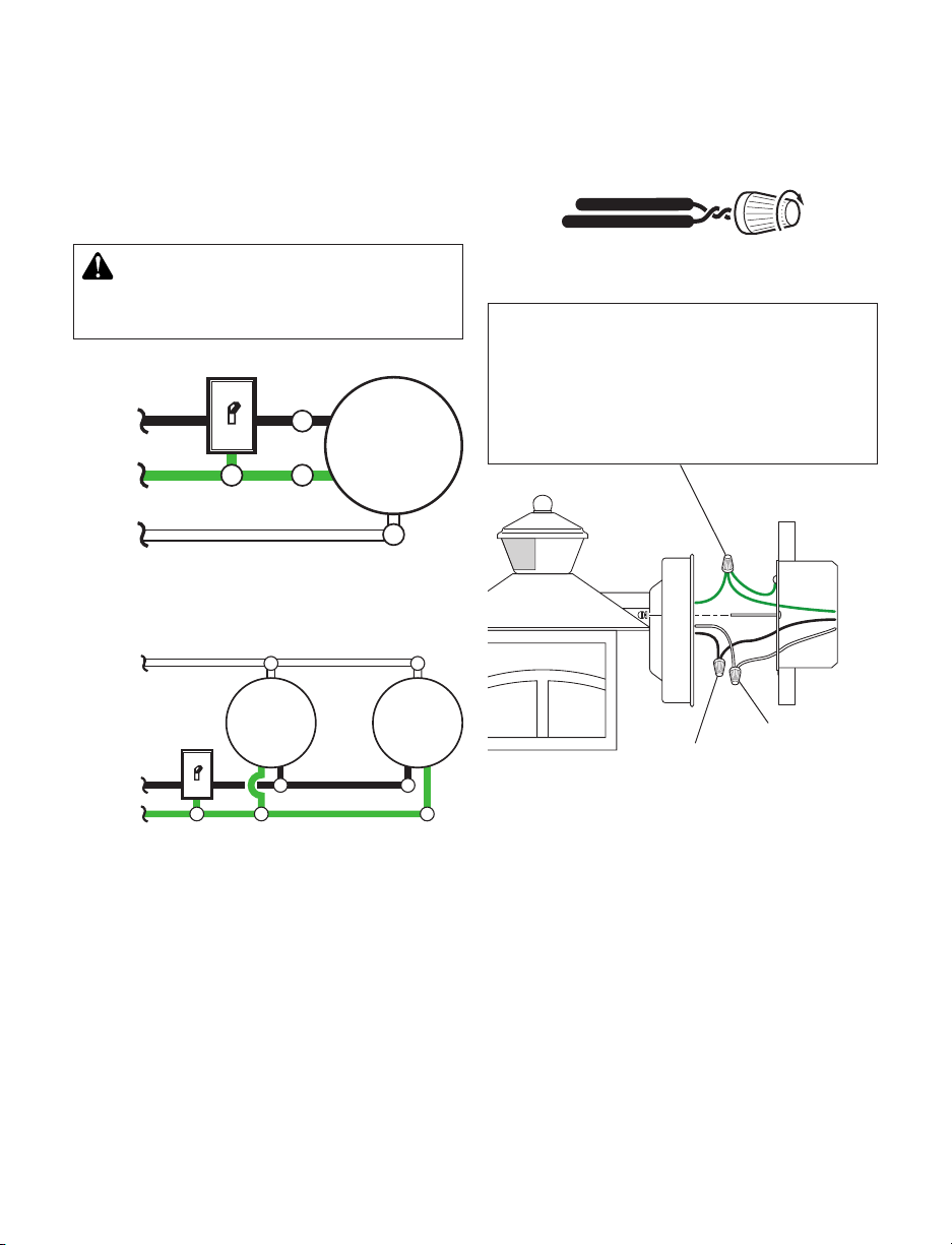
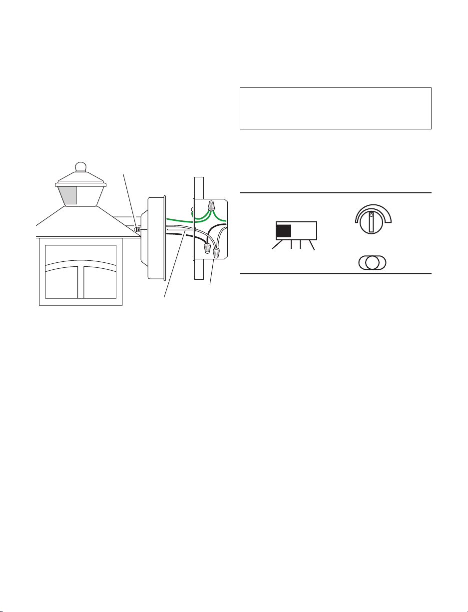
Onceyouhaveselectedthexturestobeconnectedanddeterminedtheirmaximumratings,addtheseratingsup.Forinstance,ifyouhave3xturesrated100Watts,150Watts,and75Wattsrespectively,youhaveatotalloadof325Watts.Wiring Diagram 1 – When wiring to control a standard light xture:Stripthemotionsensor’sredwireandconnecttothestandardlight’sblackwire.Connectallwhitewirestogether.Totalxtureratingsmustnotexceed360Watts(3.0A).Wiring Diagram 2 – When wiring to control another motion sensing light xture (Master /
Slave):Striptheredwireinbothlightxtures.Connecttheredwireofthecontrolling(master)xturetothered and blackwiresofthecontrolled(slave)xture.Connectallwhitewirestogether.Totalxtureratingsmustnotexceed360Watts(3.0A).Wiring Diagram 3 – When wiring so either motion light turns on the both motion lights
(Master / Master):Striptheredwireinbothlightxtures.Connecttheredwireofonexturetotheredwireofthesecondxture.Note:Inmostinstallations,anadditionalwire(samegaugeasexistinghousewire)willhavetobeinstalledinthehousetoconnectthetwoxturesasmaster/master.Connectallwhitewirestogetherandallblackwirestogether.Totalxtureratingsmustnotexceed360Watts(3.0A).Black
White
Green
or Bare
Light
Fixture
Light
Fixture
(Standard) Master Slave
Black
White
Green
or Bare
Light
Fixture
Light
Fixture
Red
Red
Wiring Diagram 1 Wiring Diagram 2
Wiring Diagram 3
Master
Black
White
Red
Green
or Bare
Master
Light
Fixture
Light
Fixture

5
598-1358-01
Junction Box
FINAL ASSEMBLY
1.Pushthewiresintothejunctionbox.Makesurethewiresfromthexturegothroughthewirepathandnowiresgetpinched.2.
Slidethextureassemblyontothemountingscrews.Tightendecorativenutsremovedinstep1ofInstallation sectionsecurelyagainstxturebase.
Mounting Screw
Decorative Nut
3.Installonemediumbaselightbulb(100Wattmaximum).4.Caulkaroundxturebasewithsiliconeweathersealant.TESTING AND ADJUSTMENTS
1.Turn on the circuit breaker and light
switch.
Note:Sensorhasa11/2minutewarmupperiodbeforeitwilldetectmotion.Whenrstturnedonwait11/2minutes.2.Set:ON-TIMEswitchtoTESTSENSITIVITYdialtoMidway
TEST 1 5 10
MINUTE
–+
SENS

6598-1358-01
30 ft.
(9.1 m)
6 ft.
(1.8 m)
180°
3.
Walkthroughthecoverageareanotingwhereyouarewhenthelightsturnon.InTESTmode,lightwillstayonfor5secondsaftersensingmotionandthenturno.4.
AdjusttheSENSITIVITYtoincreaseordecreasetherangeasneeded.Toomuchsen-
sitivitymaycausefalsetriggeringduetoheatsourcesinthecoveragearea(see
Adjustment of
Coverage AreaorTroubleshooting
section).5.SettheamountofON-TIMEyouwantthelighttostayonaftermotionisdetected(1,5,or10minutes).Maximum
Maximum Range Coverage Angle*
(Top View)
Note:Whenrstturnedonwaitabout11/2minutesforthecircuitrytocalibrate.*resetstoAutoModeatdawn.Least Sensitive Most Sensitive
esensorislesssensitivetomotiondirectlytowardsitandmoresensitivetomotionacrosscoveragearea.Sensor
Motion Motion
OPERATION
Mode: On-Time Works: Day Night
Test 5SecondsxxAuto 1,5,or10MinutesxManual ToDawn*x... back on.
1 Second
OFF then...
ManualmodeonlyworksatnightbecausedaylightreturnsthesensortoAUTO.FlipthelightswitchoforonesecondthenbackontotogglebetweenAUTOandMANUALMODE.ManualmodeworksonlywiththeON-TIMEswitchinthe1,5,or10position.MANUAL MODE

7
598-1358-01
ADJUSTMENT OF COVERAGE AREA
esensoronthislightxturedetects“motion”bythemovementofheatacrossthecoveragearea.However,followingareexamplesofobjectsthatalsoproduceheatandcancausethesensortotrigger:•PoolsofWater•AirConditioners•DryerVents•Animals•HeatingVents•AutomobileTracIfyoususpectthataheatsourceofthistypeistriggeringthesensor,reducethesensitivity.SPECIFICATIONS
Range.................................................Upto30ft.(9.1m)[varieswithsurroundingtemperature]SensingAngle.....................................Upto180°ElectricalLoad...................................Upto100WattMaximumIncandescentBulbType...........................................MediumBase,Type“A”,100WattMaximumSensorCapacity..................................Upto360Watt(3.0A)MaximumPowerRequirements...........................120VAC,60HzOperatingModes...............................TEST,AUTO,andMANUALMODEON-Timer..........................................1,5,10minutesTestTimer..........................................5SecondsManualModeTimer..........................Dusk-to-Dawn
MANUAL MODE
AUTO
TEST
ON-TIME Switch at 1, 5, or 10
minutes
MODE SWITCHING SUMMARY
Flip light switch o for
one second then back
on*
*Ifyougetconfusedwhileswitchingmodes,turnthepoweroforoneminute,thenbackon.AfterthecalibrationtimethecontrolwillbeintheAUTOmode.

8598-1358-01
TROUBLESHOOTING GUIDE
SYMPTOM POSSIBLE CAUSE SOLUTION
Lightswillnotcomeon.1.Lightswitchisturnedo.2.Lampislooseorburnedout.3.Fuseisblownorcircuitbreakeristurnedo.4.Daylightturn-oisineect.5.Sensornotdetectingmovement.6.Incorrectcircuitwiring,ifthisisanewinstallation.1.Turnlightswitchon.2.Checklampandreplaceifburnedout.3.Replacefuseorturncircuitbreakeron.4.Recheckafterdark.5.Increasesensitivity.6.Verifywiringiscorrect.Lightscomeonindaylight.1.Lightcontrolmaybeinstalledinarelativelydarklocation.2.LightcontrolisinTEST.1.extureisoperatingnormallyundertheseconditions.2.Setcontrolswitchto1,5,or10minutes.Lightscomeonfornoapparentreason.1.Lightcontrolmaybesensingsmallanimalsorautomobiletrac.2.Sensitivityissettoohigh.1.Reducesensitivity.2.Reducesensitivity.Lightsstayoncontinuously.1.esensormaybepickingupaheatsourcelikeanairvent,dryervent,orbrightlypainted,heat-reectivesurface.2.LightcontrolisinManualMode.3.Sensitivityissettoohigh.1.Reducesensitivity.2.SwitchtoAuto.3.Reducesensitivity.Lightsashonando.1.LightcontrolisintheTESTmodeandwarmingup.2.Heatbeingreectedfromotherobjectsmaybeaectingthesensor.1.Flashingisnormalundertheseconditions.2.Reducesensitivity.

9
598-1358-01
TWO YEAR LIMITED WARRANTY
isisa“LimitedWarranty”whichgivesyouspeciclegalrights.Youmayalsohaveotherrightswhichvaryfromstatetostateorprovincetoprovince.Foraperiodoftwoyearsfromthedateofpurchase,anymalfunctioncausedbyfactorydefectivepartsorworkmanshipwillbecorrectedatnochargetoyou.Not Covered -Repairservice,adjustmentandcalibrationduetomisuse,abuseornegligence,lightbulbs,batteries,andotherexpendableitemsarenotcoveredbythiswarranty.Unauthorizedserviceormodicationoftheproductorofanyfurnishedcomponentwillvoidthiswarrantyinitsentirety.iswarrantydoesnotincludereimbursementforinconve-
nience,installation,setuptime,lossofuse,unauthorizedservice,orreturnshippingcharges.
iswarrantycoversonlyHeathCoLLCassembledproductsandisnotextendedtootherequipmentandcomponentsthatacustomerusesinconjunctionwithourproducts.
THISWARRANTYISEXPRESSLYINLIEUOFALLOTHERWARRANTIES,EXPRESSORIMPLIED,INCLUDINGANYWARRANTY,REPRESENTATIONORCONDITIONOFMERCHANTABILITYORTHATTHEPRODUCTSAREFITFORANYPARTICULARPURPOSEORUSE,ANDSPECIFICALLYINLIEUOFALLSPECIAL,INDIRECT,INCIDENTAL,ORCONSEQUENTIALDAMAGES.REPAIRORREPLACEMENTSHALLBETHESOLEREMEDYOFTHECUSTOMERANDTHERESHALLBENOLIABILITYONTHEPARTOFHEATHCOLLCFORANYSPECIAL,INDIRECT,INCIDENTAL,ORCONSEQUENTIALDAMAGES,INCLUDINGBUTNOTLIMITEDTOANYLOSSOFBUSINESSORPROFITS,WHETHERORNOTFORESEEABLE.Somestatesorprovincesdonotallowtheexclusionorlimitationofincidentalorconsequentialdamages,sotheabovelimitationorexclusionmaynotapplytoyou.Please keep your dated sales receipt, it is required for all warranty requests.
TECHNICAL SERVICE
Please call 1-800-858-8501 (English speaking only) for assistance before
returning product to store.
Ifyouexperienceaproblem,followthisguide.YoumayalsowanttovisitourWebsiteat:www.
hzsupport.com.Iftheproblempersists,call*forassistanceat1-800-858-8501(Englishspeakingonly),8:00AMto5:00PMCST(M-F).Youmayalsowrite*to:HeathCoLLCP.O.Box90045BowlingGreen,KY42102-9045ATTN:TechnicalService*IfcontactingTechnicalService,pleasehavethefollowinginformationavailable:ModelNumber,DateofPurchase,andPlaceofPurchase.No Service Parts Available for this Product
Please keep your dated sales receipt, it is required for all warranty requests.
HeathCoLLCreservestherighttodiscontinueproductsandtochangespecicationsatanytimewithoutincurringanyobligationtoincorporatenewfeaturesinproductspreviouslysold.

10 598-1358-01
© 2011 HeathCo LLC 598-1358-01 S
Farol activado por el
movimiento
Luz de Coche
CARACTERÍSTICAS
•Seenciendeautomáticamentealdetectarmo-
vimiento.•Apagalaluzautomáticamente.•Lafotocélulamantienelaluzapagadadurantelashorasdiurnas.Estepaquetecontiene:•LuzdeCoche•Ménsulaytornillosparamontaje•Conectoresdealambre•ManualdelpropietarioREQUISITOS
•Elcontroldelaluzrequiere120voltiosCA.•
Sideseausarelmodomanual,elcableadodelcon-
troldebeinstalarseatravésdeuninterruptor.
•
Algunas normativas eléctricas exigen que la
instalación la realice un electricista calificado.
Revise los códigos en su área.
Modelo SL-4110
Instrucciones para su
instalación y funcionamiento
Antes de instalar, registre el número del
modelo mostrado dentro del aparato. Fije
el recibo en caso posibles reclamos por la
garantía.
Número del modelo:

11
598-1358-01
Tuerca decorativa
Paso del alambre Tornillos del tierra
Placa de
montaje
INSTALACIÓN
Tornillo de montaje
Tornillo de
montaje
del soporte Placa de
montaje
La caja de
empalme
Nota:Recomendamostenerunasistentequeayudeasostenerelconjuntodelfarolduranteelprocesodecableado.Esteaparatovieneconunsoportedemontajeuniversal.Estápre-ensambladoenelaparatoparaacomodarsealamayoríadelasaplicacionesdecajasdeempalme.Sinembargo,silasranurasdelaplacademontajenosealineanconlosagujerosdeltornillodelacajadeempalme:1.Quitedelaplacademontajelostornillosdemontajedelaparato.Nota:Noquiteeltornillodeatierra.2.Fijeelcable“exible”altornillodeatierradelaplacademontaje(VeaMétodo recomendado
de conexión a tierraparamásinformación).3.Volteelaplacademontaje4.
Volteelaplacademontajedemodoqueelagujerodepasodelalambreestéenlapartederechasuperior.
Nota:
Elagujerodepasodelalambreenlaplacademontajedebeestarubicadocomosemuestraabajoparaquelosalambresdelapartedeatrásdelaparatopuedanpasar.
5.Reinstalelostornillosdemontajedelaparatoyjelaplacademontajealacajadeempalmecomosemuestra.Paso del alambre Paso del alambre
Como se enviaron Placa volteada
y girada
Tornillos del aparato
Tornillo de
tierra
Paraunmejorfuncionamiento,instaleelaparatoacasi1.8mdelsuelo.1.Quitedostuercasdecorativas.2.Quitelaplacademontaje.3.Ajustelomásquepuedalostornillosparamontajeconsusdedos.4.Atornillelaplacademontajealacajadeempalme.ADVERTENCIA:Desconectelaalimenta-
ciónenel disyuntoroenel fusible.Coloque
cinta encima del interruptor de cortacircui-
tos y verique que la energía está apagada
en la luminaria.

12 598-1358-01
Negro a negro
Blanco a blanco
Método recomendado de conexión a
tierra
Useun“cableexible”verdedetierra(nopro-
visto)ytuerzaunextremoconelcabledesnudodelaparatoyconelcabledeatierradelacaja.Asegúrelosconunconectordecables.Asegureelotroextremodel“cableexible”coneltornillodeatierradelaplacademontaje.CABLEADO
Nota:TodoelcableadodeberealizarsedeacuerdoconelCódigoEléctricoNacionalusandotuberíaoalgúnotromedioaceptable.Póngaseencontacto
con un electricista calificado si tiene alguna
pregunta referente a la aptitud del sistema.
CUIDADO: NO conecte el cable ROJO
excepto que desee controlar otras luces
desde el detector de movimiento (Vea Co-
nexión Alterna). Conectelosalambresdelaparatoalosalambresdelacajadeempalme.Tuerzajuntoslosalambresyasegúrelosconconectoresdealambre.Sitieneunacajadeempalmedemetal,nonecesitael“cableexible”.Sinoestásegurodelmétododeconexiónatierra,consulteconelcódigolocaldeconstrucción.Luz de un movimiento
Luz de dos movimientos
Negro
Negro
Blanco
Blanco
Verde o
desnudo
Verde o
desnudo
Artefacto
de luz
Artefacto
de luz
Artefacto
de luz

13
598-1358-01
(Estándar) Maestra Esclava
Rojo
Rojo
Esquema eléctrico 1 Esquema eléctrico 2
Esquema eléctrico 3
Maestra Maestra
Rojo
Negro Negro
Negro
Blanco Blanco
Blanco
Verde o
desnudo
Verde o
desnudo
Verde o
desnudo
Artefacto
de luz
Artefacto
de luz
Artefacto
de luz
Artefacto
de luz
Artefacto
de luz
Artefacto
de luz
CONEXIÓN ALTERNA
Esteaparatovieneconundetectorconunapotenciade360Vatios.Puestoqueesteaparatotienesólounapotenciade100vatios,260vatiosdeluzadicionalpuedensercontroladosporestedetector.Cuandodeseedeterminarlaclasicacióndeunaparatonoveatansólolapotenciadelalámpara.Mirelaindicaciónqueespeciqueelvoltajemáximodelalámparaqueelaparatopuedeaceptar.Unavezquehaescogidolosaparatosqueseconectarányhadeterminadosusmáximaspotencias,súmelas.Porejemplo,sitiene3aparatosde100,150y75Vatiosrespectivamente,ustedtendráuntotalde325Vatios.Esquemaeléctrico1–Cuandoprepareunaconexiónparacontrolarunaparatodeluzestándar:Peleelalambrerojodeldetectordemovimientoyconécteloalalambrenegrodelaluzestándar.Conectetodoslosalambresblancos.Lacapacidadtotalnodebeexcederlos360Vatios(3.0A).Esquema eléctrico 2 – Cuando prepare una conexión para controlar otro aparato de luz detector
de movimiento:Peleelalambrerojoenambosaparatosdeluz.Conecteelalambrerojodelaparatocontrolador(maestro)alosalambresrojo y negrodelaparatocontrolado(esclavo).Conectetodoslosalambresblancos.Lacapacidadtotalnodebeexcederlos360Vatios(3.0A).Esquema eléctrico 3 – Cuando haga el cableado para que cualquier luz de movimiento prenda las
dos luces que detectan movimiento (Maestro / Maestro):Peleelconductorrojodeambosaparatosdeluz.Conecteelconductorrojodeunaparatoalconductorrojodelotroaparato.Nota:enlamayoríadelasinstalacionessedeberáinstalarunconductoradicional(delmismocalibrequeelconductordelacasa)dentrodelacasaparaconectarlosdosaparatoscomomaestro/maestro.Conecteentresitodoslosalambresblancosytodoslosalambresnegros.Lapotencianominaltotaldelaparatonodebesermásde360vatios(3.0A).

14 598-1358-01
PRUEBAS Y AJUSTES
1.Conecteeldisyuntoryelinterruptordelaluz.2.Ponga:ElinterruptordeTIEMPOenTEST(PRUEBA)ElcuadranteSENSITIVITY(deSENSIBI-
LIDAD)enmediorecorridoNota:Eldetectortieneunperíododecalen-
tamientode11/2minutosantesdedetectarmovimiento.Cuandoenciendaporprimeravez,espere11/2minutos.MONTAJE FINAL
1.Metalosalambresenlacajadeempalme.Asegúresequeloscablesdelaparatopasenporelpasoparaloscablesyquenoesténpinchados.2.Desliceelconjuntodelaparatosobrelostorni-
llosdemontaje.Ajustebiencontralabasedelaparatolastuercasdemontajequesequitaronenelpaso1delaseccióndeInstalación.3.Instaleunabasemediaparabombilla(100vatiosmáximo).4.Calafateealrededordelabasedelaparatoconunselladordesiliconacontralaintemperie.La caja de
empalme
Tornillo de montaje
Tuerca decorativa
TEST 1 5 10
MINUTE
–+
SENS

15
598-1358-01
9.1 m
1.8 m
180°
3.Camineporeláreadecoberturaynotesuubicacióncuandoseenciendanlasluces.EnlafaseTEST(PRUEBA),luegodedetectarmovimiento,laluzquedaráencendidapor5segundosyluegoseapagará.4.RegulelaSENSIBILIDADparaaumentarodisminuirelalcancesegúnloquenecesite.Demasiadasensibilidadpuedeocasionarfalsasalarmasdebidoafuentesdecalorenlazonadecobertura(vealasecciónAjuste de la zona
de cobertura olasecciónanálisis de averías).5.Fijeelperíododetiempo(ON-TIME)quelaluzdebequedarseprendidadespuésdedetectarmovimiento(1,5o10minutos).Alcance Máximo Ángulo de
Cobertura Máxima*
(Vista desde arriba)
Nota:Cuandoenciendaporprimeravez,espere11/2minutosparaqueloscircuitossecalibren.
*SeponeenAutomáticoalamanecer.Lo menos sensible Lo más sensible
Dentrodeláreadecoberturaeldetectoresmenossensibleamovimientosensudirecciónymássensibleamovimientostransversales.Detector
OPERACIÓN
Movimiento Movimiento ...préndalo.
1 segundo
APAGADO
luego...
ElmodomanualfuncionasóloporlanocheporquelaluzdeldíaponealdetectorenmodoAUTOMÁTICO.ApagueelinterruptorporunsegundoyvuélvaloaprenderparaconmutarentreMODOAU-
TOMÁTICOyMANUAL.Elmodomanualfuncionasola-
menteconelinterruptordeDU-
RACIÓNDETIEMPOenlaposiciónde1,5o10minutos.MODO MANUAL
Modalidad:Atiempo:Trabaja:DíaNochePrueba 5segundosxxAutomático 1,5o10minutosxManual Hastaelamanecer*x

16 598-1358-01
Mueva el interruptor de
tiempo (ON-TIME) a 1, 5 o
10 minutos
RESUMEN DE LAS MODALIDADES
DEL INTERRUPTOR
Apague el interruptor por
un segundo y préndalo de
nuevo*
PRUEBA
AUTOM.
MODO
MANUAL
REGULACIÓN DEL ÁREA DE
COBERTURA
Eldetectordeesteaparatodeluzdetecta“movi-
miento”debidoalmovimientodelcaloratravésdeláreadecobertura.Sinembargo,acontinuacióntieneejemplosdeobjetosquetambiénproducircalorypuedenhacerqueeldetectorseactive:•Charcosdeagua•Acondicionadoresdeaire•Ventosasdelasecadora•Animales•Ventosasdecalefacción•TrácoautomotorSisospechaqueunafuentedecalordeestetipoestáactivandoeldetector,reduzcalasensibilidad.*Siseconfundemientrascambiadefases,apaguelaelectricidadporunminutoypréndaladenuevo.DespuésdeltiempodecalibraciónelcontrolestaráenfaseAUTO(MÁTICA).ESPECIFICACIONES
Alcance..................................................
Hasta9.1m.(varíaconlatemperaturadelmedioambiente).
Ángulodedetección..............................Hasta180°CargaEléctrica......................................Hastaunmáximode100vatiosdeincandescenteTipodebombilla...................................Casquillomediano,tipo“A”de100vatiosmáximoCapacidaddelDetector.........................
Focodetungstenodehasta360vatios(3.0A)comomáximo
RequisitosdeEnergía............................120VCA,60HzFasesdeOperación................................PRUEBA,AUTOMÁTICOyMODOMANUALTemporizadordeduración(delencendido)......................................1,5o10minutosTemporizadordeprueba........................5segundosTemporizadordelafasemanual............Delatardeceralamanecer

17
598-1358-01
GUÍA DE INVESTIGACIÓN DE AVERÍAS
SÍNTOMA POSIBLE CAUSA SOLUCIÓN
Laslucesnoseprenden.1.Elinterruptordeluzestáapagado.2.Labombillaestáojaoquemada.3.Elfusibleestáquemadooelcortacircuitosestáapagado.4.Lamodalidaddeapagadoduranteeldíaestáenefecto.5.Elsensornodetectaelmovimiento.6.Alambradoincorrecto,siéstaesunanuevainstalación.1.Enciendaelinterruptordeluz.2.Reviselalámparaycámbielasiestáquemada.3.Cambieelfusibleenciendaeldisyuntor.4.Revíselodespuésdelanochecer.5.Aumentalasensibilidad.6.Veriquequeelcableadoestécorrecto.Laslucesseprendenduranteeldía.1.Elcontroldeluzpuedeestarinstaladoenunlugarrela-
tivamenteobscuro.2.ElcontroldeluzestáenfasedePrueba.1.Elaparatoestáfuncionandonormalmentebajoestascondiciones.2.
Fijeelinterruptordecontrolalaposiciónde20minutos.
Laslucesseprendensinningunarazónaparente.1.Elcontroldeluzpuedeestardetectandoanimalespequeñosoeltrásitodeautomóviles.2.LaSensibilidadesdemasiadoalta.1.Reduzcalasensibilidad.2.Reduzcalasensibilidad.Laslucessequedanprendidascontinuamente.1.Elsensorpuededetectarfuentesdecalor,comoductosdecalefacciónydeaireacondicionado,osuperciesresplandecientesquereejanlaluz.2.ElcontroldeluzestáenfaseManual.3.LaSensibilidadesdemasiadoalta.1.Reduzcalasensibilidad.2.CámbielaaAuto.3.Reduzcalasensibilidad.Laluceseprendenyseapagan.1.ElcontroldeluzestáenfasedePruebaycalentándose.2.Elcalorquesereejadeotrosobjetospuedenestarafectandoaldetector.1.
Elprenderseyapagarseesnormalbajoestascondiciones.
2.Reduzcalasensibilidad.

18 598-1358-01
SERVICIO TÉCNICO
Favor de llamar al 1-800-858-8501 (sólo para hablar en inglés) para pedir ayuda
antes de devolver el producto a la tienda.
Sitienealgúnproblema,sigaestaguía.UstedpuedetambiénvisitarnuestrositioWeb:www.hzsu-
pport.com.Sielproblemacontinúa,llameal1-800-858-8501(sóloparahablareninglés),de8:00AMa5:00PMCST(L-V).Ustedpuedetambiénescribira:HeathCoLLCP.O.Box90045BowlingGreen,KY42102-9045ATTN:TechnicalService(ServicioTécnico)*SisellamaalServicioTécnico,porfavortenerlistalasiguienteinformación:NúmerodeModelo,FechadecomprayLugardecompra.No hay piezas de servicio disponibles para este producto.
Por favor guarde su recibo de venta fechado; se lo requiere para cualquier solicitud de garantía.
GARANTÍA LIMITADA A 2 AÑOS
Estaesuna“GarantíaLimitada”queledaaUd.derechoslegalesespecícos.Ustedpuedetambiéntenerotrosderechosquevaríandeestadoaestadoodeprovinciaaprovincia.Porunperíodode2añosdesdelafechadecompra,cualquiermalfuncionamientoocasionadoporpartesdefectuosasdefábricaomanodeobraserácorregidosincargoparaUd.No cubierto -Serviciodereparación,ajusteycalibracióndebidoalmaluso,abusoonegligencia,bombillas,baterías,uotraspartesfungiblesnoestáncubiertasporestagarantía.LosServiciosnoautorizadosomodicacionesdelproductoodecualquiercomponentequeseproveeinvalidaránestagarantíaensutotalidad.Estagarantíanoincluyereembolsoporinconveniencia,instalación,tiempodeinstalación,perdidadeuso,servicionoautorizado,ocostosdetransportederetorno.EstagarantíacubresolamentelosproductosensambladosporHeathCoLLCynoseextiendeaotrosequiposocom-
ponentesqueelconsumidorusajuntoconnuestrosproductos.ESTAGARANTÍAESTÁEXPRESAMENTEENLUGARDEOTRASGARANTÍAS,EXPRESADASOSOBREENTENDIDAS,INCLUYENDOCUALQUIERGARANTÍA,REPRESENTACIÓNOCONDICIÓNDECOMERCIABILIDADOQUELOSPRODUCTOSSEADAPTENPARACUALQUIERPROPÓSITOOUSOENPARTICULAR,YESPECIFICAMENTEENLUGARDETODOSLOSDAÑOSESPECIALES,INDIRECTOS,INCIDENTALESYCONSECUENTES.LAREPARACIÓNOELREEMPLAZODEBERÍASERLAÚNICASOLUCIÓNDELCLIENTEYNOHABRÁRESPONSABILIDADPORPARTEDEHEATHCOLLCPORCUALQUIERDAÑOESPECIAL,INDIRECTO,INCIDENTALOCONSECUENTE,INCLUIDOSPERONOLIMITADOSACUALQUIERPÉRDIDADENEGOCIOOGANACIASSEANONOPREVISIBLES.Algunosestadosoprovinciasnopermitenlaexclusiónolimitacióndedañosincidentalesoconsecuentes,demodoquelalimitaciónoexclusiónarribaindicadapuedequenoseapliqueaUd.Por favor guarde su recibo de venta fechado; se lo requiere para cualquier solicitud de garantía.
HeathCoLLCsereservaelderechodedescontinuarproductosydecambiarespecicacionesacual-
quiermomentosinincurrirenningunaobligacióndetenerqueincorporarnuevascaracterísticasenlosproductosvendidosconanterioridad.

19
598-1358-01
Lanterne de carrosse
Lampe cochère activée
par le mouvement
CARACTÉRISTIQUES
•S’allumeautomatiquementlorsdeladétectiond’unmouvement.•S’éteintautomatiquement.•Cellulephoto-électriquequigardel’éclairagefermépendantlajournée.Cetemballagecontient:•Lanternedecarrosse•Visetxationdemontage•Serre-ls•GuidedupropriétaireEXIGENCES
•Lacommanded’éclairageexigeducourant120Vc.a.•Pourutiliserlemodedefonctionnementmanuel,lacommanded’éclairagedoitêtrereliéeàuninterrupteur.•Dans certaines localités, le code de l’électri-
cité exige que l’installation soit confiée à un
électricien qualifié. Veuillez vérifier les codes
en vigueur dans votre région.
Avant l’installation, inscrivez ici le numéro
de modèle qui se trouve à l’intérieur de
l’appareil. Joignez-y le reçu d’achat pour
les réclamations sous garantie.
Numéro de modèle :
Modèle SL-4110
Instructions d'installation
et mode d'emploi
© 2011 HeathCo LLC 598-1358-01 F

20 598-1358-01
INSTALLATION
Passage des ls Vis de mise
à la terre
Plaque de
montage
Écrou décoratif
Vis de montage
Vis de
montage
du support Plaque de
montage
Boîte de
jonction
Note :Ilestrecommandédedemanderàuneautrepersonnedetenirlalanternependantlepassagedesls.MISEENGARDE :Coupezl’alimentation
audisjoncteurouaufusible.Mettezleruban
gommé sur l’interrupteur du disjoncteur
et vériez que l’alimentation est coupée
au montage. Celuminairevousestfourniavecunsupportuniversel;déjàxéauluminaire,cesupportconvientàlamajoritédesboîtesderaccordementélectrique.Toutefois,silesrainuresdelaplaquedemontagenecorrespondentpasauxtrousdesvisdelaboîte:1.Retirezlesvisdexationauluminairedelaplaquedemontage.Note :Neretirezpaslavisdemiseàlaterre.2.Fixezla«rallonge»duldeterreàlavisedemiseàlaterredelaplaquedemontage(consultezlasectionMéthode de mise à la terre
recommandéepourplusdedétails).3.Retournezlaplaquedemontage.4.Faitestournerlaplaquedemontagedesortequel’oricedepassagedeslssetrouvedanslecoinsupérieurdroit.Note :L’oricedepassagedeslsdelaplaquedemontagedoitêtreplacécommeillustréci-dessouspourpermettrelepassagedeslsàl’arrièreduluminaire.5.Remettezenplacelesvisdexationaulumi-
naireetlavisdemiseàlaterre,puisxezlaplaquedemontageàlaboîtederaccordement,commeillustré.Vis de xation au
luminaire
Vis de mise à
la terre
Passage des ls Passage des ls
Tel qu’expédié Plaque retournée,
après rotation
Pourunrendementoptimal,montezleluminaireàenviron1,8mau-dessusdusol.1.Retirezlesdeuxécrousdécoratifs.2.Enleverlaplaquedemontage.3.Serrezàlamainlesvisdelacroix.4.Fixerlaplaquedemontageàlaboîtedejonc-
tion.
Table of contents
Languages:
Other Health Zenith Outdoor Light manuals
Popular Outdoor Light manuals by other brands

Probrite
Probrite DAWN12-PC-4K-BZ INSTALLATION, USAGE, & CARE GUIDE

urban ambiance
urban ambiance UHP3917 installation instructions

Qazqa
Qazqa Charlois WL Black Lux instruction manual

Modern Forms
Modern Forms 419-Outdoor Wall Sconce Series installation instructions

Maxim Lighting
Maxim Lighting Cathedral manual

IKEA
IKEA SOLSKUR manual